Week 4-1D Element Creation Challenge
OBJECTIVE:
To mesh the given component with the Size of 5 Units and create 1D elements on the following component with the given cross-section and DOF.
CAD MODEL IMAGE:
PROCEDURE:
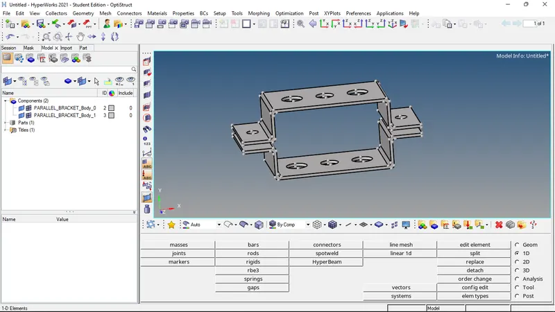
1. Import the given model of the parallel bracket by import geometry command.
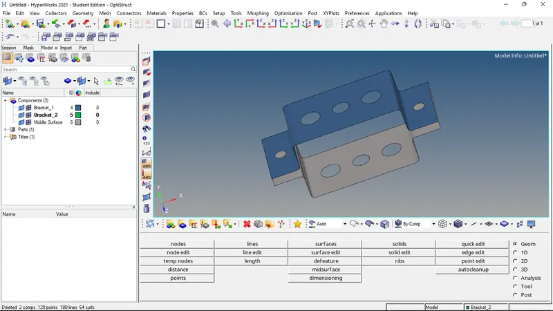
2. Create mid-surfaces for components 1 and 2 by mid-surfacing command. The mid surface of component 2 should be assigned to the bracket 2 component.
3. Assign material to the components. Steel has been assigned in this case.
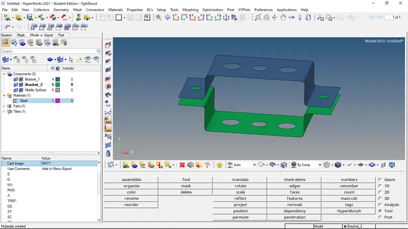
4. Properties are also created for both the components and are assigned to both of them.
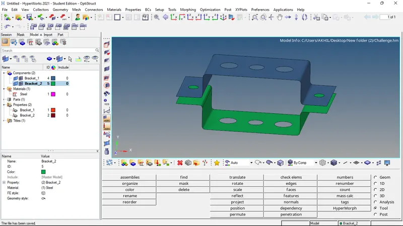
5. A washer split of 5mm is made on each of the holes before meshing the part.
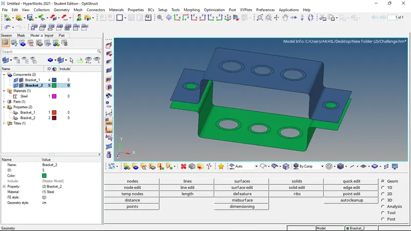
6. Both the components are meshed using the auto mesh feature and the nodes are adjusted around the washer split to create a proper mesh. A mesh size of 5mm is given as mentioned.
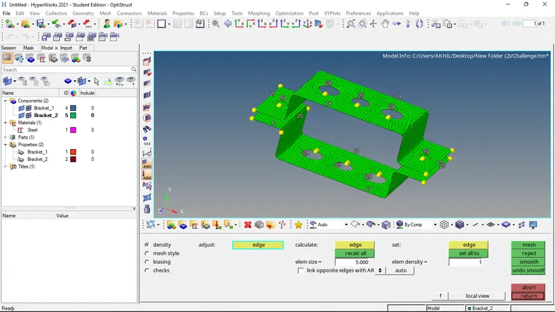
7. Now RBE2 and RBE3 elements are created on the holes a,d,c,d and e with the properties mentioned.
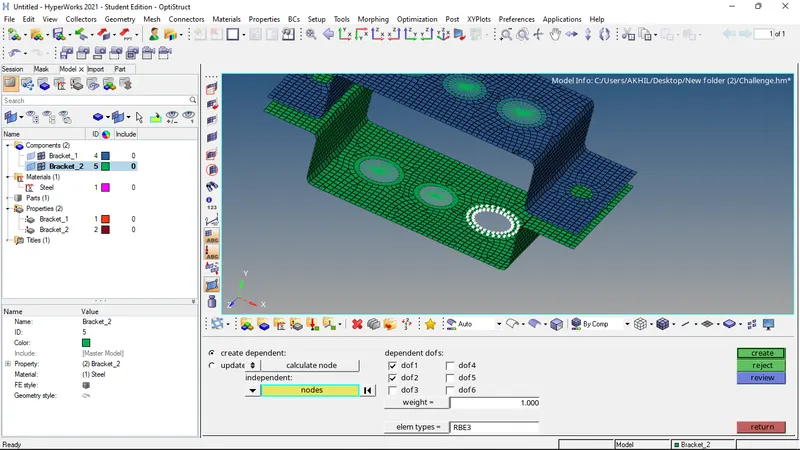
8. Now the cross-sections of the rod, beam, and bar elements are created using the hyper beam option.
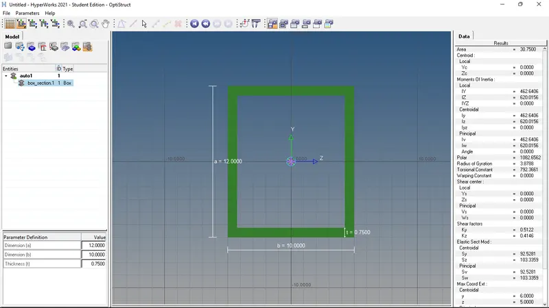
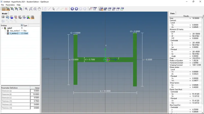
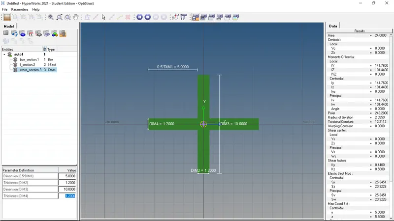
9. Rod, Beam, and bar elements are created between the components.
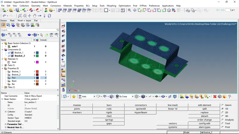
10. Properties are created for bar, beam, and rod elements, and the corresponding properties are assigned to the elements.
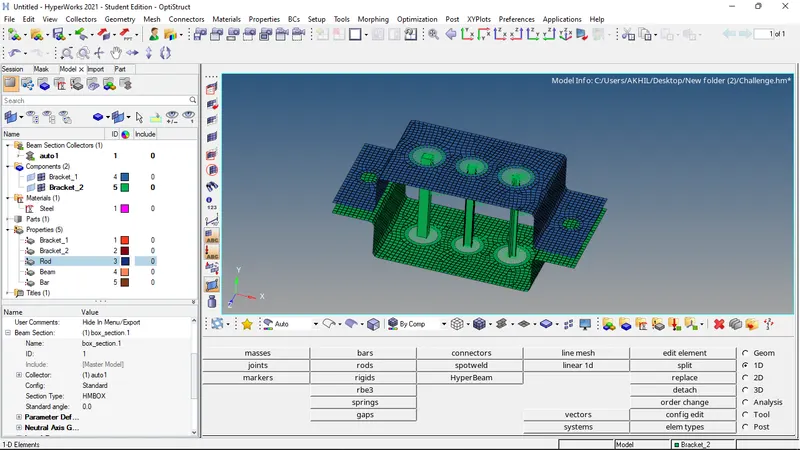
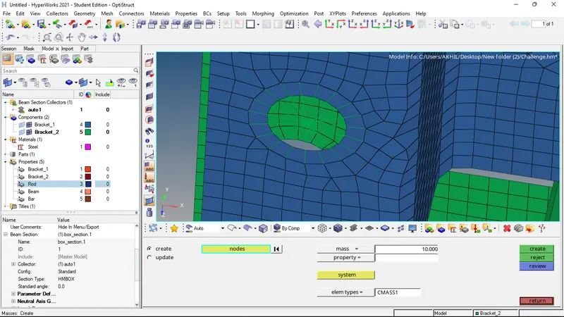
11. Mass of magnitude 10 is assigned to the rbe2 elements on points d and e.
12. For creating spring elements between the components, The nodes of the faces 'f' excluding the adjacent nodes of the rbe2 elements are selected and masked and then the node section is done. The nodes on both the faces are selected and the spring elements are created using the spring option in the connectors tab.
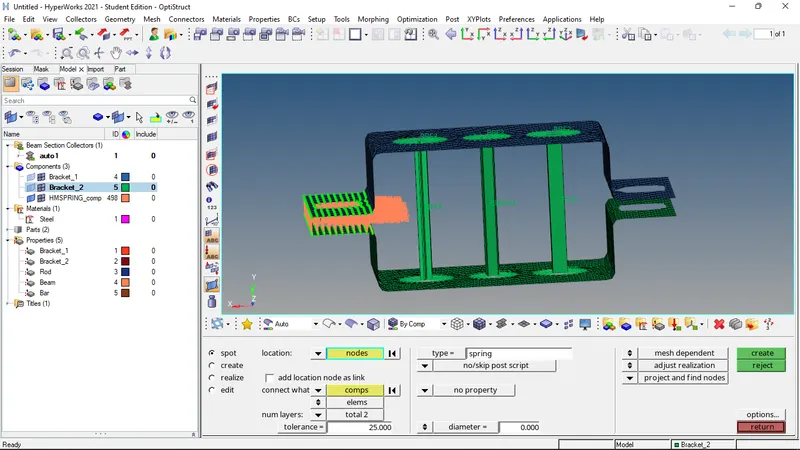
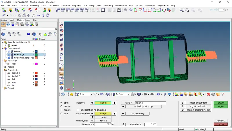
13. The same procedure is used for the other faces. And the masked nodes are unmasked.
RESULT:
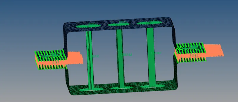
The given bracket is successfully meshed by the given mesh size of 5 and the 1-D elements of the mentioned cross-section are also successfully mentioned at the mentioned points. Spring elements are also added between the given components.
FINAL MODEL IMAGE: