Simulation of Flow through a pipe in OpenFoam
OBJECTIVE:
- Write a program in MATLAB that can automatically generate the computational mesh for any wedge angle and grading schemes.
- Generate the blockMeshDict file for two types of buondary conditions - Wedge Type & Symmetry Type.
- Simulate the fluid flow using the generated blockMeshDict file and icoFoam solver in OpenFoam.
- Plot the velocity profile obtained in the fully developed region.
- Compare the velocity profile at different positions along the length of the pipe.
- Post process the velocity and shear stress results.
- Compare the results obtained in OpeanFoam for both the types of boundary conditions with the Hagen poiseuille's equation.
INTRODUCTION:
In this project, we shall simulate the laminar flow through a pipe using OpenFoam and comaper the results with the analytical values obtained using Hagen- Poiseuille equation.
Hagen-Poiseuille equation:
is a physical law that gives the pressure drop in an inconpressible and Newtonian fluid in laminar flow flowing through along cylindrical pipe of constant cross section. The Hagen-Poiseuille equation is only valid for long pipes whose length is relatively large compared to therir diameter.
Hydrodynamic entrance length:
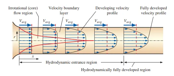
Fluid with low viscosity reaches its free stream velocities at very samll distances as there is no hinderance with other molecules. But fluids with high viscocity takes a large distance to reach the free stream velocity. At the entrance the velocity of fluid near to the wall will have less velocity as there will be friction between the wall and the fluid towards centre velocity will be increasing and after a lenght the velocity is same at all positions. This length till which velocity varies is called hydrodynamic entrance region/legth. The region after this region is fully developed region.
Since there are no velocity gradients outside the hydrodynamic boundary layer, the shear stresses are negligible. In this unditurbed flow, the viscosity of the fluid plays no role. But within the boundary layer, the shear stresses are usually no longer negligible and have a decisive influence on the flow. Even if the boundary layer is defibed very precisely, the change of the properties of the flow inside and outside of this "sharp" boundary is smooth.
Fully Developed Laminar flow:
Flow is said to have reached Fully developed flow if it have the same velocity profile at any cross-section within the pipe.
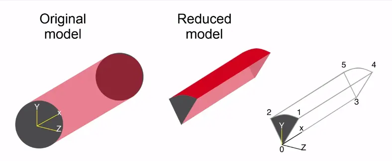
For the simulation of laminar flow through a pipe as creating mesh for whole pipe and rumming simulation may not be supported in all computers. So a wedge shaped profile is created and simulations are performed on the wedge shaped profile.
Values:
- Diameter D = 0.02m
- R= D/2
- mu =0.00089 `N/m^2`(dynamic viscosity)
- `rho`=1000`(kg)/m^2`
- Re =2100 (dimension less reynold number)
- L = 0.06*Re.D
Formulas used for calculation:
`V_(avg) = (Re.u)/(rho.D)`
`V_(max) = 2.V_(avg)` = .0.1875`ms^-1`
`Deltap =(8.mu.L.V_(avg))/r^2` = 18.2 Pa
Shear stress `tau`= `(2*mu*v_(max).R)/r^2`
* Sector which is to be createg using blockMeshDict file, has a sweep angle less than 5 since the angle is small the arc can be approximated to a straight line, it can be illustrated as follow,
so the co-ordinates for the vertices of the vector is calculated using the trignomatric functions,`y=d/2.cos(theta/2) and z=d/2.sind(theta/2)` it can be illustrated in a simple way as follow,
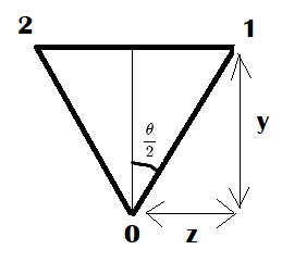
In this simulation angle of `3^0` is taken accordingly the blockMeshDict file is created by file parsing in matlab.
Boundaries included are - inlet,outlet both which are of type patch
- Front and back which is of type wall
- Axis which is of type empty
- Top which is of type wall
Matlab Program:
In this project we have used MATLAB to write a program that will generate the mesh file (blockMeshDict file) for OpenFoam. The geometry used is wedge made out of single block and for different wedge angles our MATLAN program creates the rerquired BlockMeshDict file.
clear all
close all
clc

% input

theta =input('enter the angle');  % angle of wedge
Re=2100;
D=0.02;
Le = 0.06*Re*D;
L = Le+0.3;
R=D/2;
mu =8.9e-4;  %viscosity of water
rho =1000;  % density of water in kg/m^3
nu = mu/rho;  %kinematic viscosity


% Calculation of pressure and velocity;

v_avg = (Re*mu)/(D*rho);  %average velocity
v_max = 2*v_avg;  %max velocity
deltap = (8*mu*v_avg*L)/(R^2);  % pressure drop

% Vertices of the wedge

v0 = [0 0 0];
v1 = [0 R*cosd(theta/2) -R*sind(theta/2)];
v2 = [0 R*cosd(theta/2) R*sind(theta/2)];
v3 = [L 0 0];
v4 = [L R*cosd(theta/2) -R*sind(theta/2)];
v5 = [L R*cosd(theta/2) R*sind(theta/2)];

grading=0.2;
b1=50;
b2=1;
b3=200;


%printing the file
text1='/*------------------------------------*- C++ -*---------------------------===--------*';
text2='|  ========                   |                                                      |';
text3='|        /  F ield           | OpenFoam:  The Open Source CFD Toolbox               |';
text4='|       /   O peration       | Version:   8.1                                       |';
text5='|      /    A nd             | Web:       www.https://openfoam.org                  |';
text6='|     /     M anipulation    |                                                      |';
text7='*-----------------------------------------------------------------------------------*/';

text8='//**********************************************************************************//';


%Creating file
f1 =fopen('blockMeshDict','w');

fprintf(f1,'%sn',text1);
fprintf(f1,'%sn',text2);
fprintf(f1,'%sn',text3);
fprintf(f1,'%sn',text4);
fprintf(f1,'%sn',text5);
fprintf(f1,'%sn',text6);
fprintf(f1,'%snn',text7);

fprintf(f1,'FoamFile n{n');
fprintf(f1,'%16s %10sn','version','2.0;');
fprintf(f1,'%16s %12sn','format','ascii;');
fprintf(f1,'%16s %17sn','class','dictionary;');
fprintf(f1,'%16s %20sn','object','blockMeshDict;');
fprintf(f1,'%2sn','}');

fprintf(f1,'%2snn','//*************************************//');
fprintf(f1,'%2snn','convertToMeters 1;');
fprintf(f1,'vertices n (n');
fprintf(f1,'t(%d %d %d)n',v0);
fprintf(f1,'t(%d %d %d)n',v1);
fprintf(f1,'t(%d %d %d)n',v2);
fprintf(f1,'t(%d %d %d)n',v3);
fprintf(f1,'t(%d %d %d)n',v4);
fprintf(f1,'t(%d %d %d)n',v5);
fprintf(f1,' %2snn',');');

fprintf(f1,'blocks n(n');
fprintf(f1,'t %s (%d %d %d) %s (%d 1 1) n','hex (0 1 2 0 3 4 5 3)',b1,b2,b3,'simpleGrading',grading);
fprintf(f1,' %2snn',');');

fprintf(f1, 'edges n(n');
fprintf(f1,' t %s (0 %d 0)n','arc 1 2',R);
fprintf(f1,'t %s (%d %d 0)n','arc 4 5',L,R);
fprintf(f1,'%2snn', ');');


fprintf(f1,'boundary n(n');
fprintf(f1,'t %5s n','axis','{');
fprintf(f1,'t %13s %sn','type','empty;');
fprintf(f1,'t %14sn %18sn','faces','(');
fprintf(f1,'t t %15sn %19snn %14snn','(0 3 3 0)',');','}');

fprintf(f1,' t %5s n','top','{');
fprintf(f1,'t %13s %sn','type','wall;');
fprintf(f1,'t %14sn %18sn','faces','(');
fprintf(f1,'t t %15sn %19snn %14snn','(2 5 4 1)',');','}');

fprintf(f1,' t %5s n','inlet','{');
fprintf(f1,'t %13s %sn','type','patch;');
fprintf(f1,'t %14sn %18sn','faces','(');
fprintf(f1,'t t %15sn %19snn %14snn','(0 0 2 1)',');','}');

fprintf(f1,' t %5s n','outlet','{');
fprintf(f1,'t %13s %sn','type','patch;');
fprintf(f1,'t %14sn %18sn','faces','(');
fprintf(f1,'t t %15sn %19snn %14snn','(3 4 5 3)',');','}');

fprintf(f1,' t %5s n','wedgeFront','{');
fprintf(f1,'t %13s %sn','type','wedge;');
fprintf(f1,'t %14sn %18sn','faces','(');
fprintf(f1,'t t %15sn %19snn %14snn','(0 3 5 2)',');','}');

fprintf(f1,' t %5s n','wedgeBack','{');
fprintf(f1,'t %13s %sn','type','wedge;');
fprintf(f1,'t %14sn %18sn','faces','(');
fprintf(f1,'t t %15sn %19snn %14snn %snn','(0 1 4 3)',');','}',');');

fprintf(f1,'mergePatchPairs n (n);n');
fprintf(f1,'%2snn','//******************************************************//');
fclose(f1);
The following file is auto generated file for wedge angle 3 which is derived from the above MATLAB code. This file is used in place of existing blockMeshDict file which is in the incompressible solver from openFoam software. Note thet the dolver used here is icoFoam. The same technique is used for wedge angle 4 as well. The only difference is specifying the angle as degree in matlab code instead of 3 degrees.
BlockMeshDict File:
/*------------------------------------*- C++ -*---------------------------===--------*
|  ========                   |                                                      |
|        /  F ield           | OpenFoam:  The Open Source CFD Toolbox               |
|       /   O peration       | Version:   8.1                                       |
|      /    A nd             | Web:       www.https://openfoam.org                  |
|     /     M anipulation    |                                                      |
*-----------------------------------------------------------------------------------*/

FoamFile
{
         version       2.0;
          format       ascii;
           class       dictionary;
          object       blockMeshDict;
 }
//*************************************//

convertToMeters 1;

vertices
 (
	(0 0 0)
	(0 9.996573e-03 -2.617695e-04)
	(0 9.996573e-03 2.617695e-04)
	(2.820000e+00 0 0)
	(2.820000e+00 9.996573e-03 -2.617695e-04)
	(2.820000e+00 9.996573e-03 2.617695e-04)
 );

blocks
(
	 hex (0 1 2 0 3 4 5 3) (50 1 200) simpleGrading (2.000000e-01 1 1)
 );

edges
(
 	 arc 1 2 (0 1.000000e-02 0)
	 arc 4 5 (2.820000e+00 1.000000e-02 0)
);

boundary
(
	  axis
	     {
	          type empty;
	          faces
                  (
	 	       (0 3 3 0)
                  );

              }

 	  top
 	     {
	          type wall;
	          faces
                  (
	 	       (2 5 4 1)
                  );

              }

 	 inlet
 	     {
	          type patch;
	          faces
                  (
	 	       (0 0 2 1)
                  );

              }

 	 outlet
 	     {
	          type patch;
	          faces
                  (
	 	       (3 4 5 3)
                  );

              }

 	 wedgeFront
 	     {
	          type wedge;
	          faces
                  (
	 	       (0 3 5 2)
                  );

              }

 	 wedgeBack
 	     {
	          type wedge;
	          faces
                  (
	 	       (0 1 4 3)
                  );

              }

 );

mergePatchPairs
 (
);
//******************************************************//
ControlDict file:
/*--------------------------------*- C++ -*----------------------------------*
  =========                 |
  \      /  F ield         | OpenFOAM: The Open Source CFD Toolbox
   \    /   O peration     | Website:  https://openfoam.org
    \  /    A nd           | Version:  8
     \/     M anipulation  |
*---------------------------------------------------------------------------*/
FoamFile
{
    version     2.0;
    format      ascii;
    class       dictionary;
    location    "system";
    object      controlDict;
}
// * * * * * * * * * * * * * * * * * * * * * * * * * * * * * * * * * * * * * //

application     icoFoam;

startFrom       startTime;

startTime       0;

stopAt          endTime;

endTime         50;

deltaT          0.01;

writeControl    timeStep;

writeInterval   200;

purgeWrite      0;

writeFormat     ascii;

writePrecision  6;

writeCompression off;

timeFormat      general;

timePrecision   6;

runTimeModifiable true;


// ************************************************************************* //
Initial conditions = Kinematic pressure Drop
/*--------------------------------*- C++ -*----------------------------------*
  =========                 |
  \      /  F ield         | OpenFOAM: The Open Source CFD Toolbox
   \    /   O peration     | Website:  https://openfoam.org
    \  /    A nd           | Version:  8
     \/     M anipulation  |
*---------------------------------------------------------------------------*/
FoamFile
{
    version     2.0;
    format      ascii;
    class       volScalarField;
    object      p;
}
// * * * * * * * * * * * * * * * * * * * * * * * * * * * * * * * * * * * * * //

dimensions      [0 2 -2 0 0 0 0];

internalField   uniform 0;

boundaryField
{
    aixs
    {
        type            empty;
    }

    inlet
    {
    	type		zeroGradient;
    }

    outlet
    {
        type            fixedValue;
        value		 uniform 0.018;
    }

    top
    {
    	type		 zeroGradient;

    }

    wedgeFront
    {
    	type		 wedge;

    }

    wedgeBack
    {
        type            wedge;
    }
 }

// ************************************************************************* //
Initila condition - Inlet Average Velocity
/*--------------------------------*- C++ -*----------------------------------*
  =========                 |
  \      /  F ield         | OpenFOAM: The Open Source CFD Toolbox
   \    /   O peration     | Website:  https://openfoam.org
    \  /    A nd           | Version:  8
     \/     M anipulation  |
*---------------------------------------------------------------------------*/
FoamFile
{
    version     2.0;
    format      ascii;
    class       volVectorField;
    object      U;
}
// * * * * * * * * * * * * * * * * * * * * * * * * * * * * * * * * * * * * * //

dimensions      [0 1 -1 0 0 0 0];

internalField   uniform (0.0937312 0 0);

boundaryField
{
    axis
    {
        type            empty;
    }

    inlet
    {
        type            fixedValue;
        value           uniform (0.0937312 0 0);
    }

    outlet
    {
    	type		zeroGradient;
    }

    top
    {
    	type             fixedValue;
    	value            uniform (0 0 0);
    }

    wedgeFront
    {
        type            wedge;
    }

    wedgeBack
    {
    	type            wedge;
    }
}

// ************************************************************************* //
Transport Properties - Kinematic Viscosity:
/*--------------------------------*- C++ -*----------------------------------*
  =========                 |
  \      /  F ield         | OpenFOAM: The Open Source CFD Toolbox
   \    /   O peration     | Website:  https://openfoam.org
    \  /    A nd           | Version:  8
     \/     M anipulation  |
*---------------------------------------------------------------------------*/
FoamFile
{
    version     2.0;
    format      ascii;
    class       dictionary;
    location    "constant";
    object      transportProperties;
}
// * * * * * * * * * * * * * * * * * * * * * * * * * * * * * * * * * * * * * //

nu              [0 2 -1 0 0 0 0] 1e-06;


// ************************************************************************* //
Once all the above file are set, blockMesh is typed in the command window to genertae the mesh. The mesh so genertaed can be viewed in the postprocessing tool ParaView. After that checkMesh command can be used to check wether the mesh is ok.
Once both of the above commands run without any error we can run the simulation by typinf icoFoam in teh terminal window. After successfully runnung the simulation the result obtained is viewed and the postprocessed in paraView.
Results:
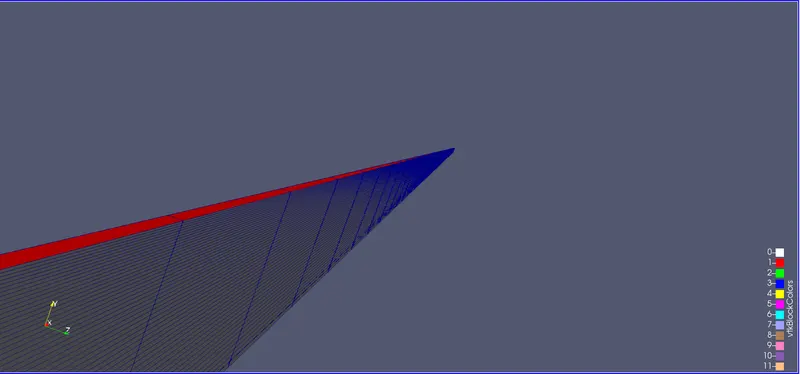
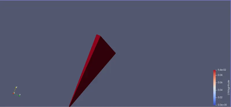
For wedge angle 3 degree
To further validate the result we can take velocity profile along the radial directionb of pipe. For this we can use plotover line tool of paraView, which provides us with a line probe. This line probe is placed at different points along the length of pipe and hence the velocity at different points is plotted.
Velocity Profiles
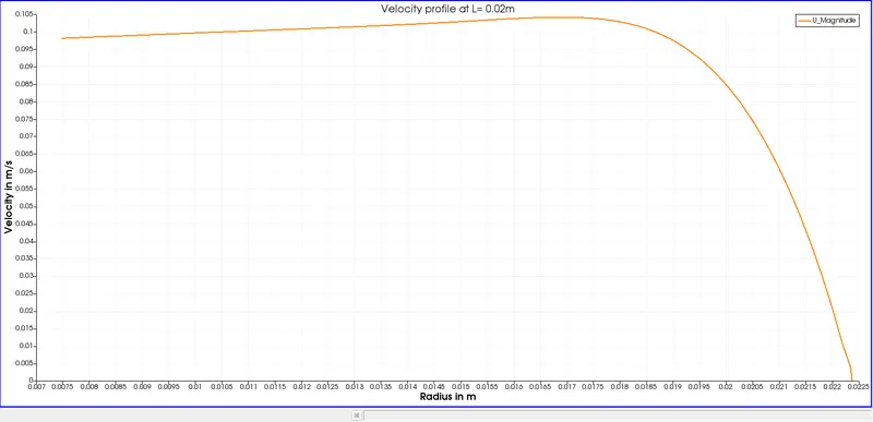
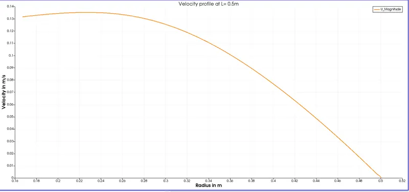
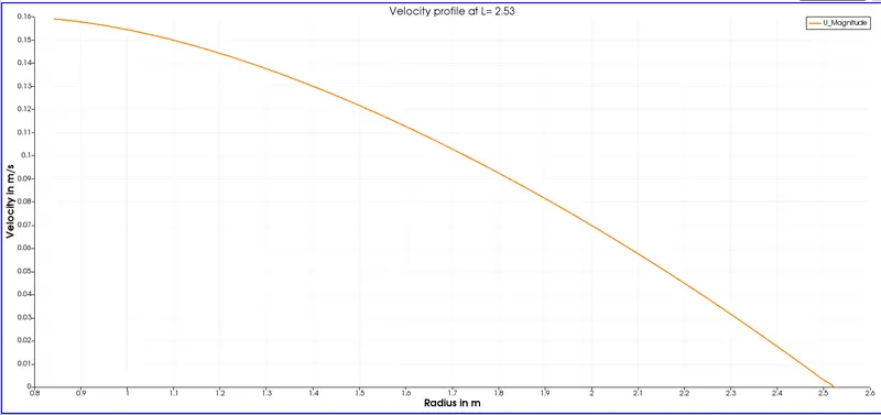
Since we are simulating for small sector, it is not possible to obtain the complete velocity profile. So the sector is mirrored using reflect option present in paraview. Then we get our sector under consideration, here Ymin, mirrored and hence complete velociity profile can be obtained.
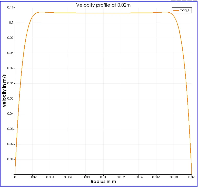
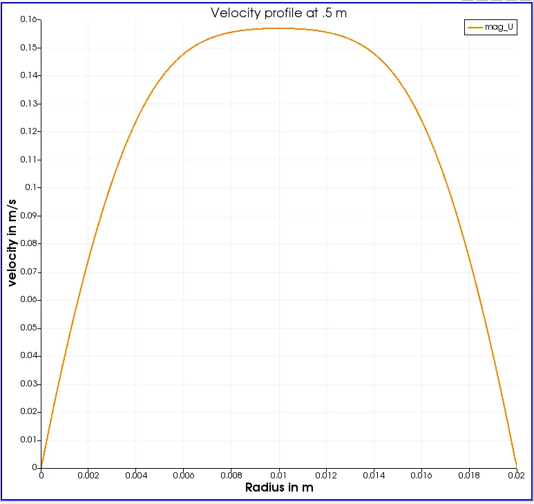
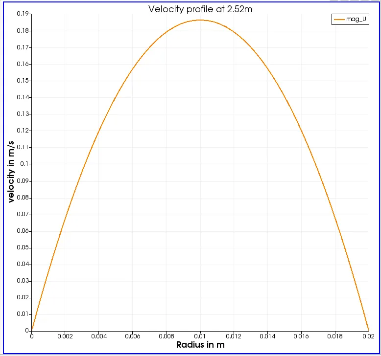
It is evident from the results that after a certain distance the parabolic velocity is formed and this profile remains unchanged in the axial direction, which in turn tells us that the entry length we set up with respwct to conditions inside the domain is absolutely sufficent for obatining the fully developed flow regime.
Plotting of shear stress:
plotting shear stress is not staight forward as plotting the velocity profile. Because in paraview tau is not ccalculated directly, so it becomes relevant that we first calculate tau and then use plot overline command to plot the shear stress.
we have newton's law for viscous flow,`tau = mu.(delu)/(dely)`this can be used to calculate the shear atreaa. Steps calculation are listed below.
- We need to calculate magnitude of vector U, this can be achived using the mag option present in the calculator. If we provide mag(U) in the calulator we will get the magnitude of velocity.
- Once magnitude of velocity is computed next step is to calculate its gradient, this can be achived by inserting gradient of unstructured dat set, this is a computational option present in the paraview. Once this option is inserted from filters we acn provide the calculated velocity gradient aws input form filters we can provide the calculated velocity gradient as input and hence the gradient of velocity can be calculated.
- once the gradient is calsulated, dynamic viscosity of water at 25 c is multiplied ,`mu=0.00089(kg)/(m.s)`hence tau is calculated.
- Using plotover line, the probe can be placed anywhere along the radial direction and shear plot can be obtained.
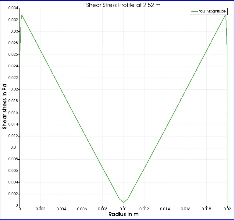
As we can see that shear stress increases along the radius i.e shear stress is 0 at 0.01 m of the pipe and it is maximum at walls.
Simulation is performed for another wedge angle of 4 in similar way and theresult are compared with each other respectively.
| wedge angle | Maximum velocity obtained through simulation | Hagen poiseuille | Error |
| 3 | 0.1854 | 0.1869 | 0.0015 |
| 4 | 0.1857 | 0.1869 | 0.0012 |