Week 11- Assembly Workbench
AIM: Create the part models and assembly for the given drawings below with a report.
DRAWING 1 (QUICK RETURN MECHANISM):
REPORT ANALYSIS:
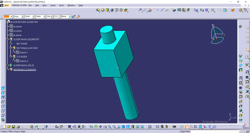
Intially created the part of the drawing in the part workbench.
Sketches and CAD Part:
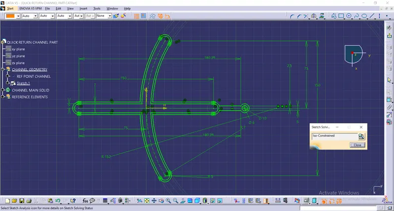
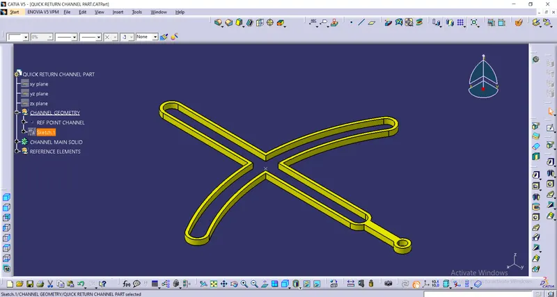
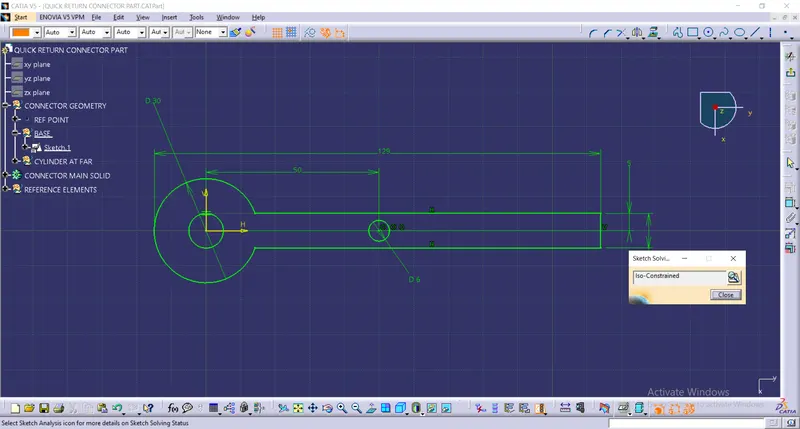
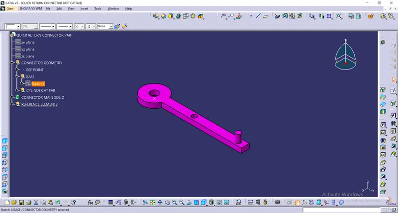
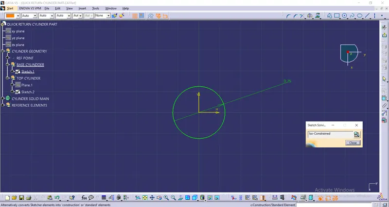
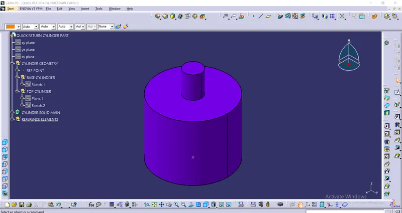
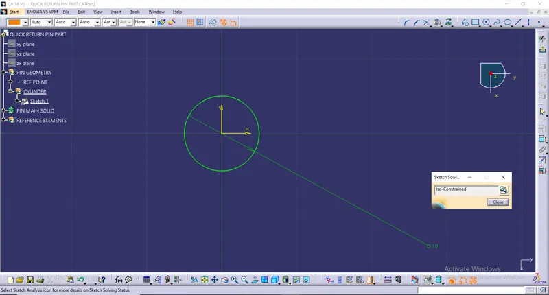
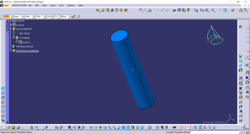
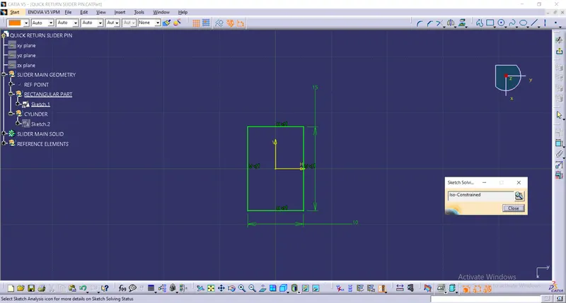
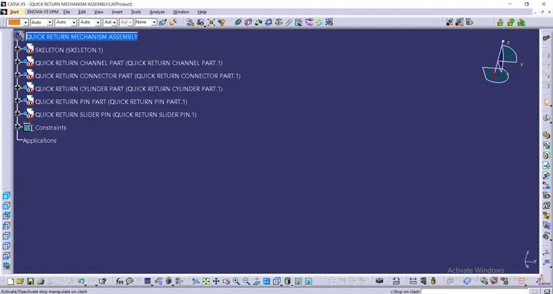
After creating all the parts go to the Assembly Workbench and insert every part to the assembly workbench:
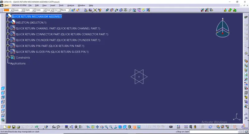
Now create an origin for the assembly, here 'Skeleton' is the origin for the assembly and order the tree where Skeleton should come at the top.
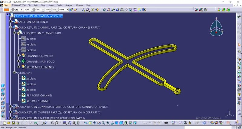
Now Publish very each plane, reference point and reference axis for each part in the respective part tree.
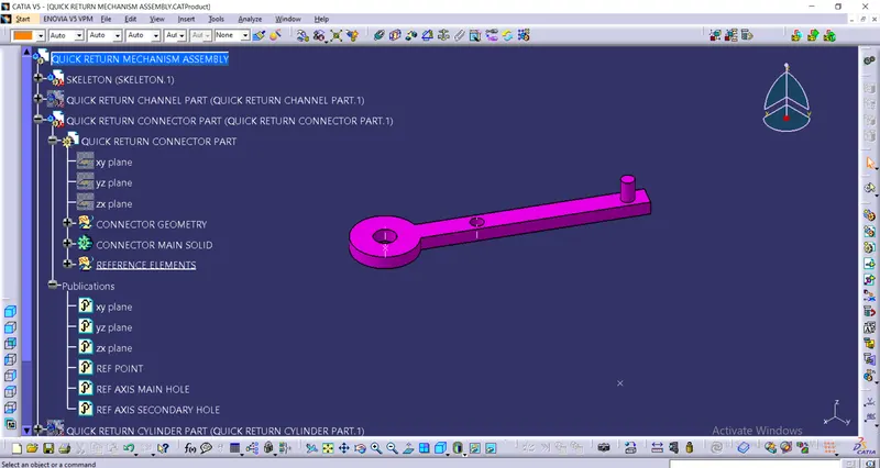
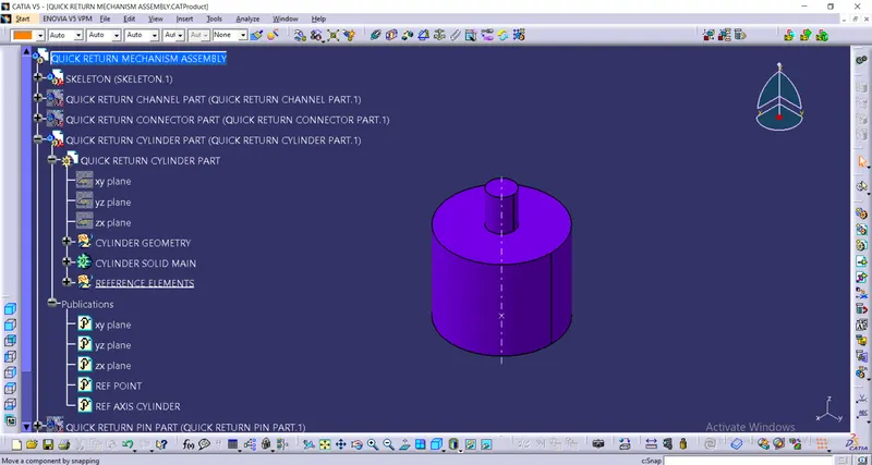
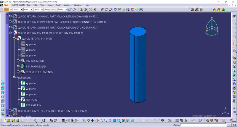
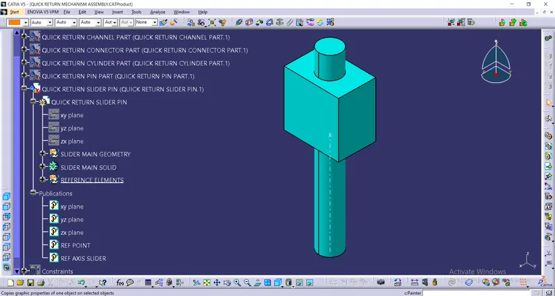
Now try constraint the part in way wanted.
intially Fix the Skeleton so that it does not move.
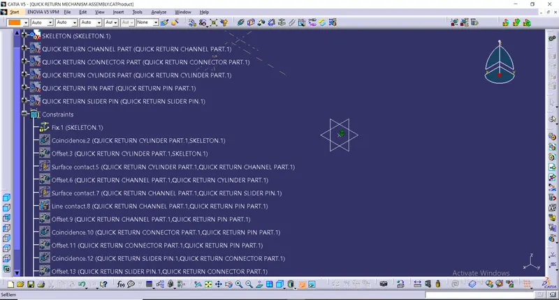
Now coincide the axis of the cylinder to the skeleton point then offset it to 0.
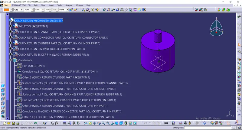
Then use Surface Contact to align the axis of cylinder and channel axis and Offset it inorder to align the top face of channel and cylinder.
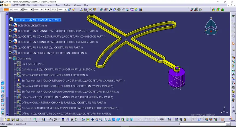
Now use Surface Contact to align slider and channel.
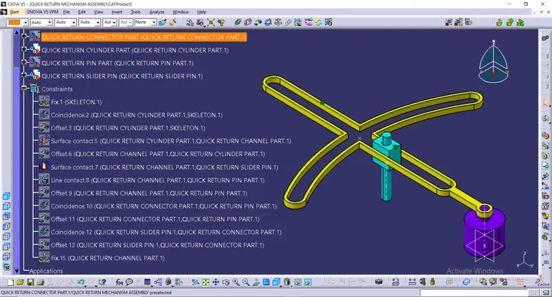
Now provide the Line Contact to flush Pin and Channel and Offset it to required value.
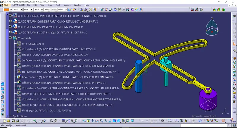
Then Coincide the Pin and Connector and provide the Offset to the required value.
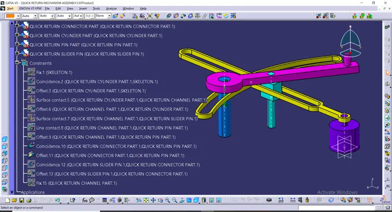
Now Coincide and Offset Slider Pin and Connector to the required value and finally Fix channel.
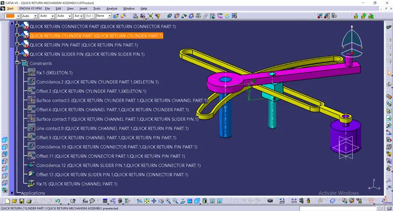
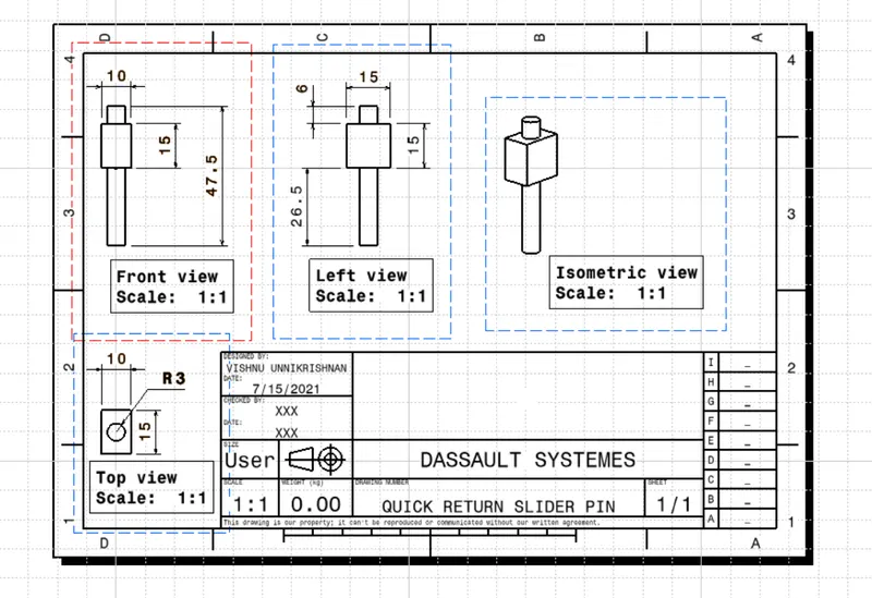
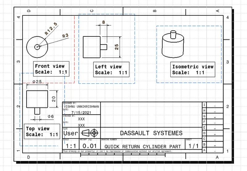
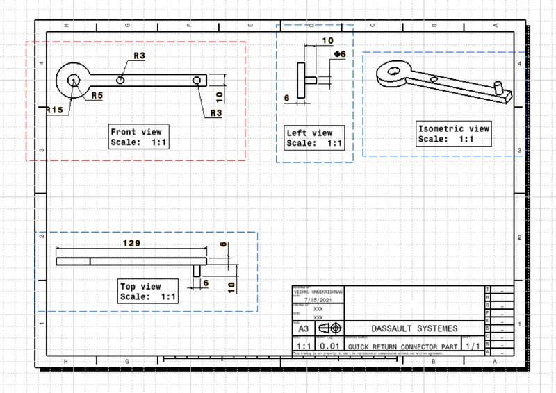
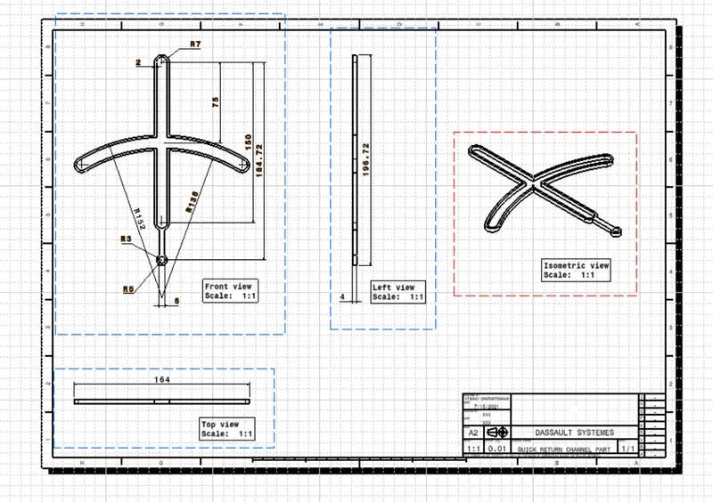
2D DRAWING USING DRAFTING TOOL: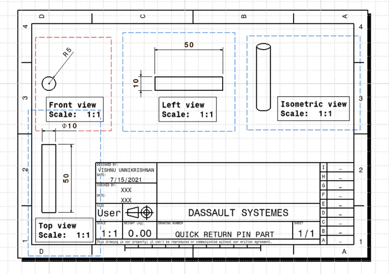
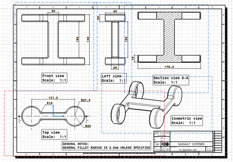
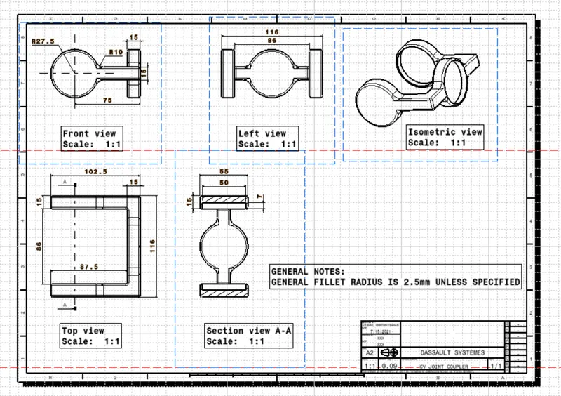
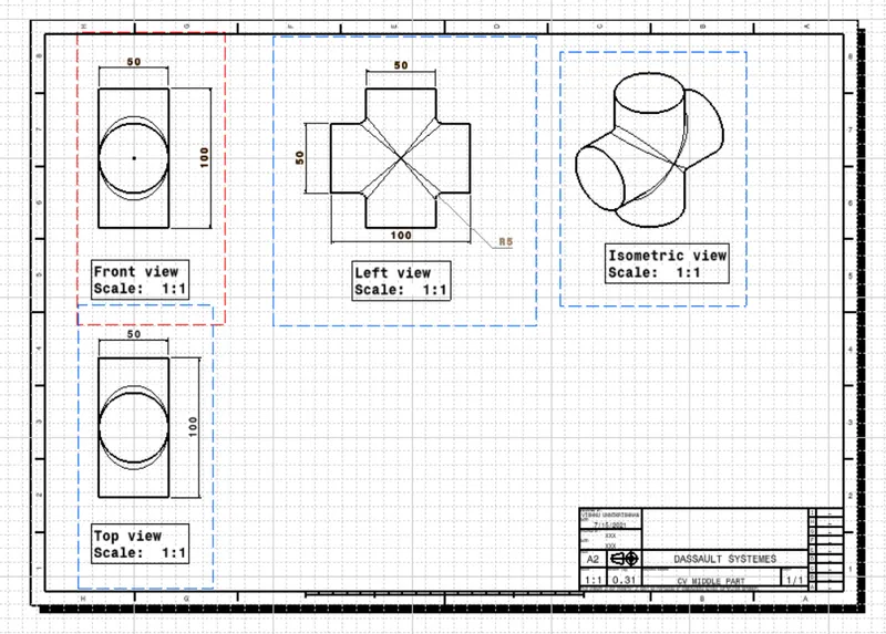
DRAWING 2 (CV JOINT):
REPORT ANALYSIS:
Intially created the part of the drawing in the part workbench.
Sketches and CAD Part:
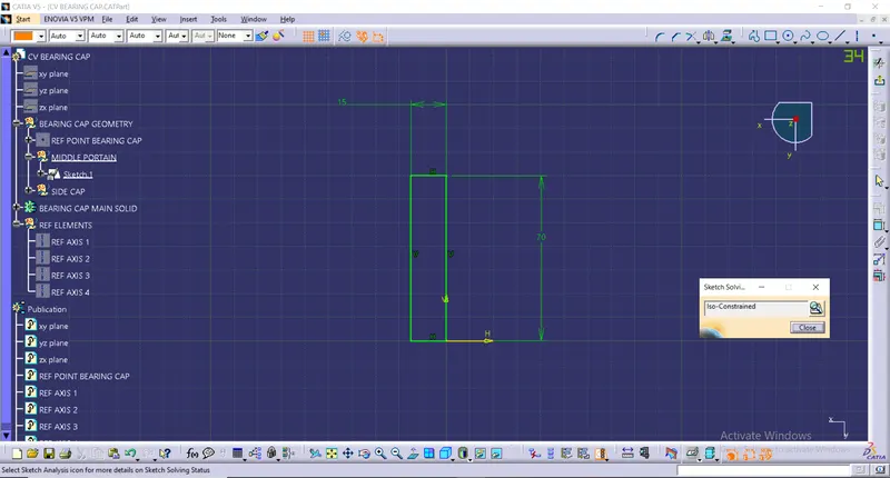
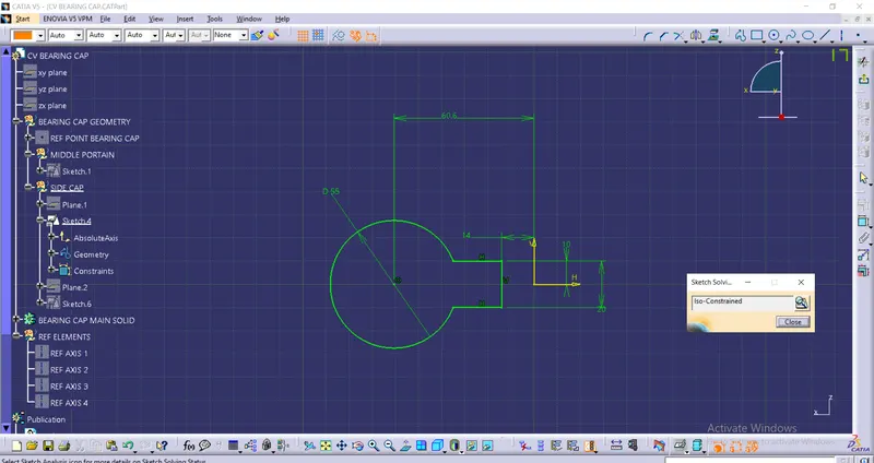
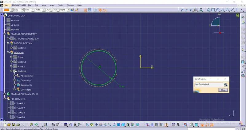
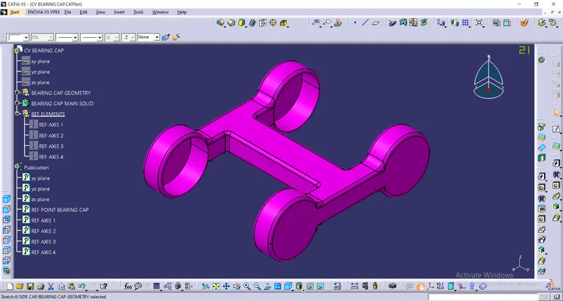
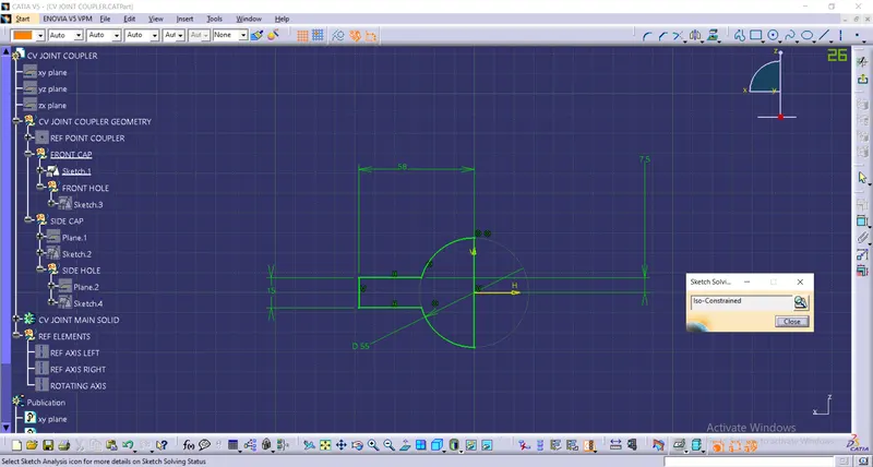
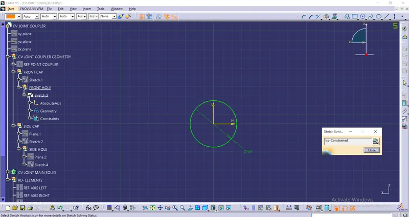
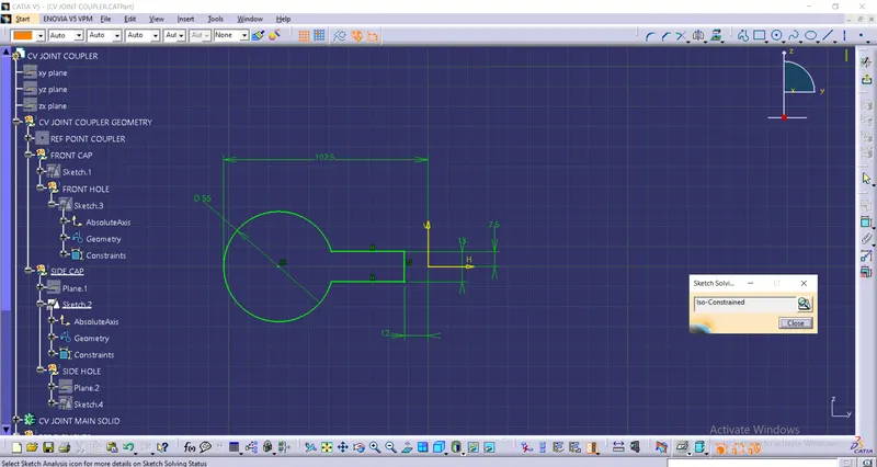
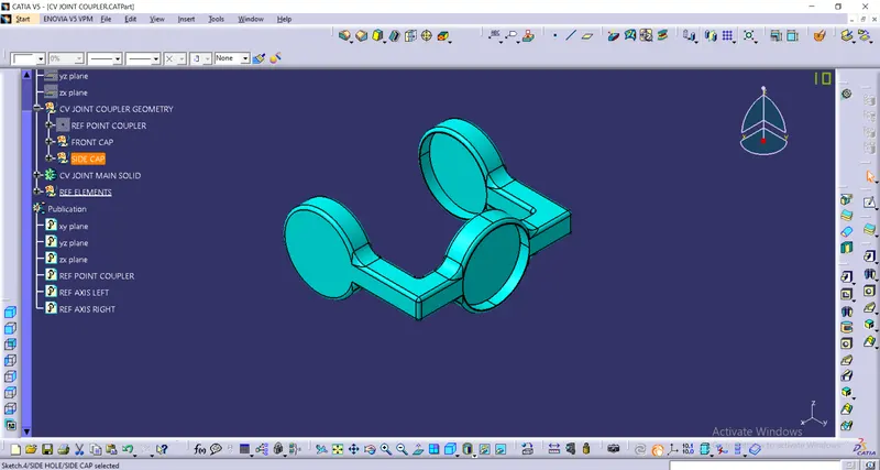
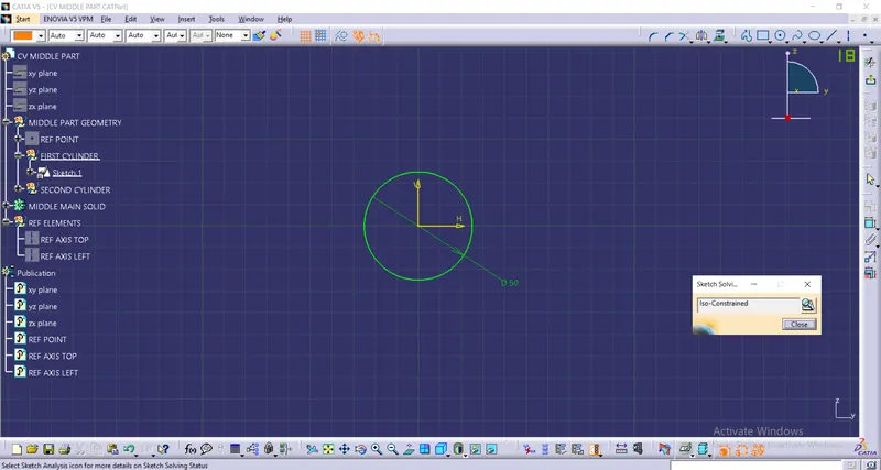
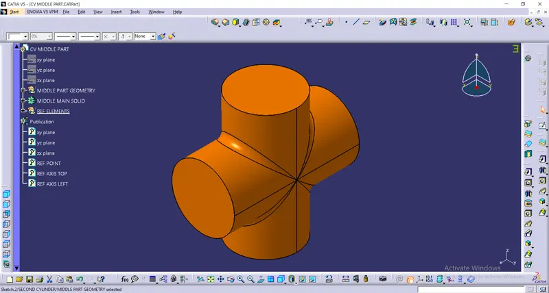
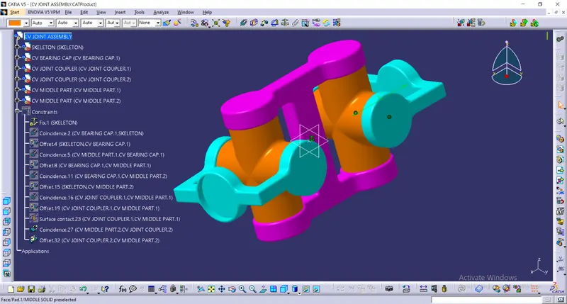
After creating all the parts go to the Assembly Workbench and insert every part to the assembly workbench:
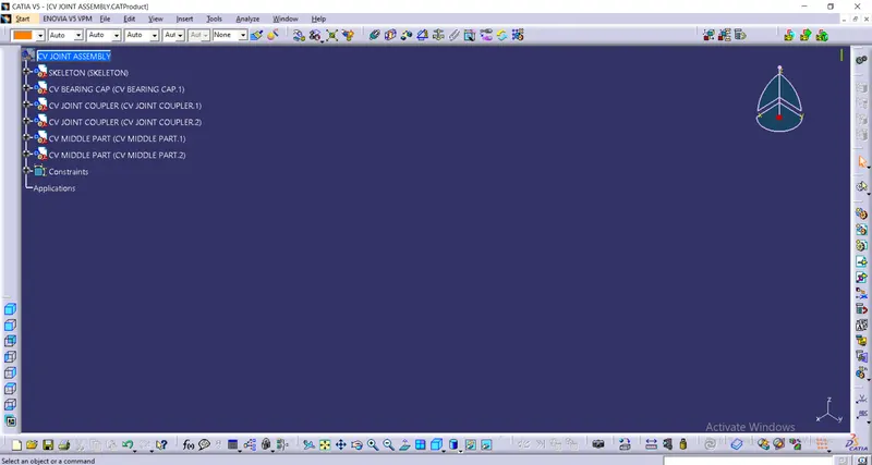
Now create an origin for the assembly, here 'Skeleton' is the origin for the assembly and order the tree where Skeleton should come at the top.
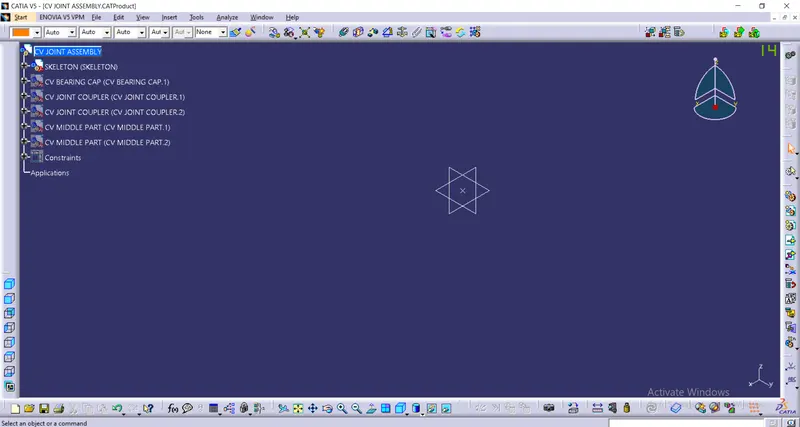
Now Publish very each plane, reference point and reference axis for each part in the respective part tree.
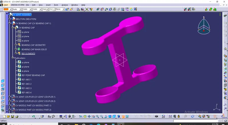
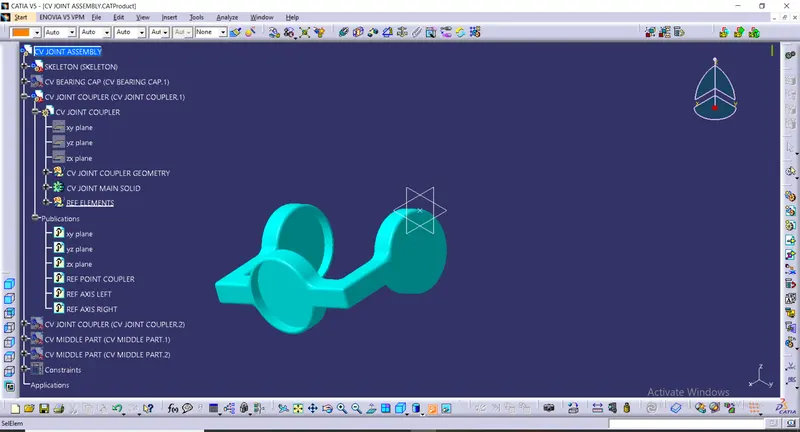
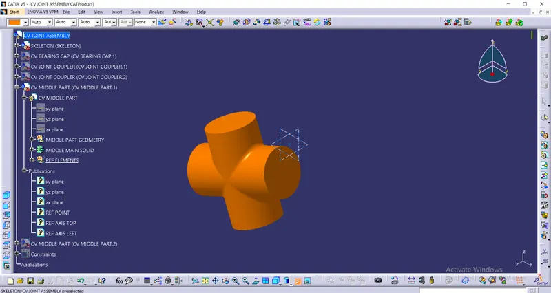
Now try constraint the part in way wanted.
intially Fix the Skeleton so that it does not move.
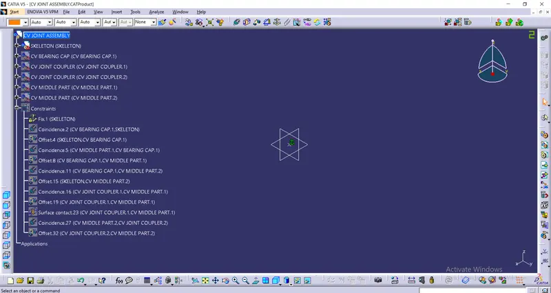
Now Coincide the Skeleton point with Bearing Point Offset to the required value.
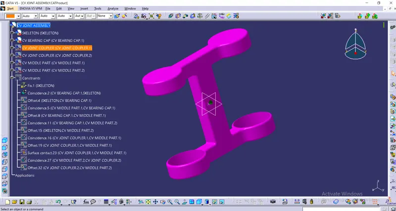
Now Coincide the axis of bearing and the middle part and offset the point to the required value.
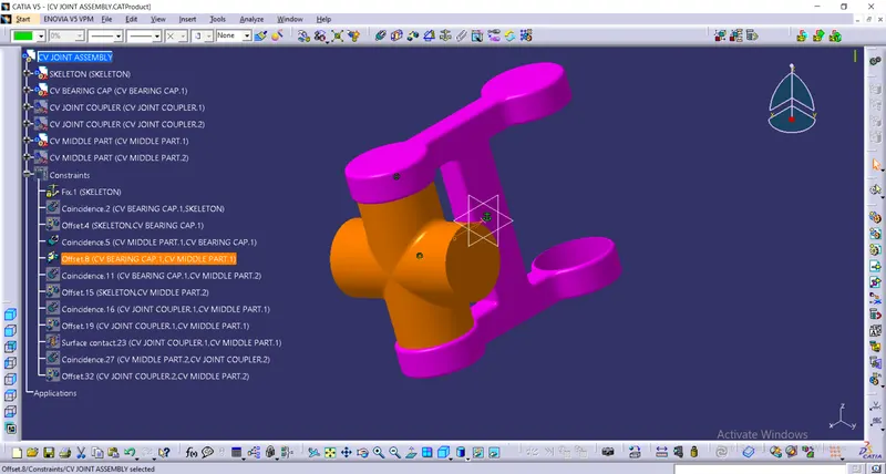
Now Coincide the axis of other bearing and the middle part and offset the point to the required value.
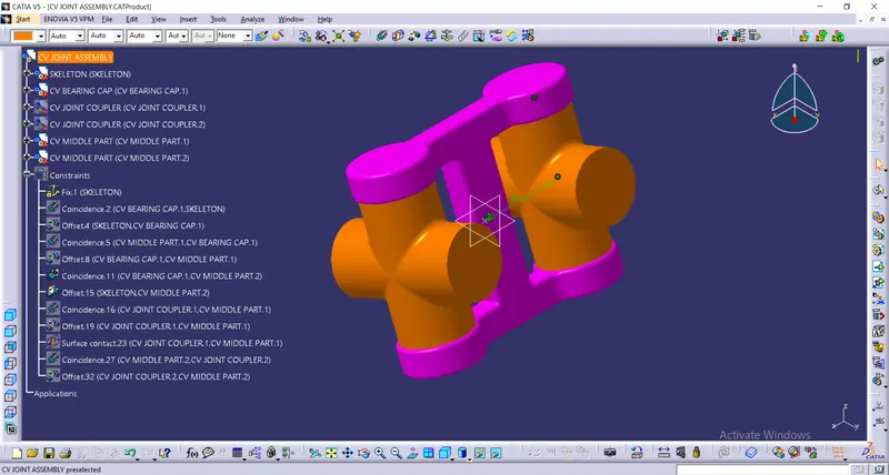
Now coincide the axis of the coupler and the middle part and offset the yz plane to the required value.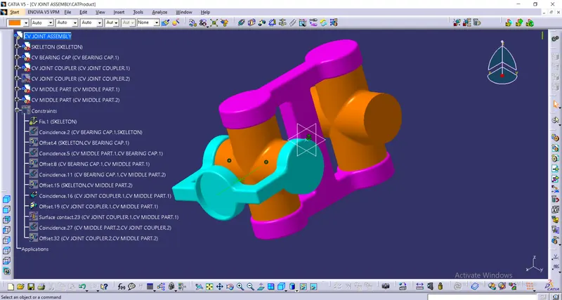
Now coincide the axis of the other coupler and the middle part and offset the yz plane to the required value.
2D DRAWING USING DRAFTING TOOL: