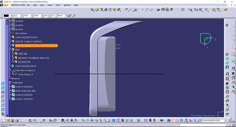
Week 9 - Attachment Feature Creation - Challenge 1
AIM: Create the rib for the Centre console coin holder considering the design rules mentioned in the video.
REPORT ON DRAFT ANALYSIS:
Given Class A Surface:
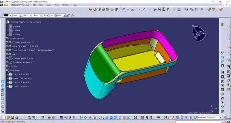
STEP 1: Check the connectivity of the Class A Surface
- Ensure that there is no gap between the component, using join command.
- We can visually check it or by clicking boundary command.
- It has double boundary.
STEP 2: Find the tooling axis of the component. The tooling axis is nothing but the mould opens or cavity opens.
- Check visaully which is the best possible tooling axis.
- Check all three axis.
- Perpendicular to the base is the best possible tooling axis.
Creating a Tooling axis along perpendicular to base:
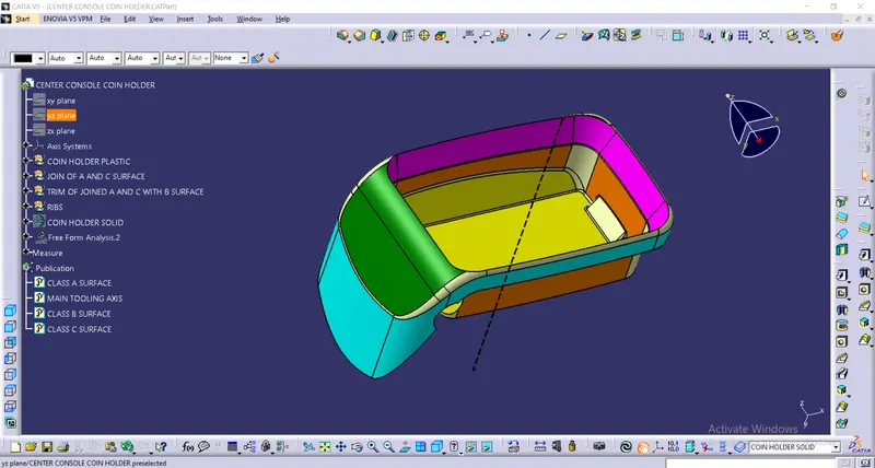
Therefore the main tooling axis is along perpendicular to base.
Now perform the Draft analysis using the Featured Draft Anal ysis tool in the tools.
Then after opening the draft analysis tool box go for the compass and place the compass alinged to tooling axis and click on the lock symbol after alinging and further click on the surface.
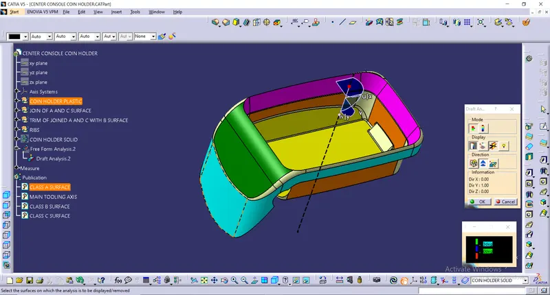
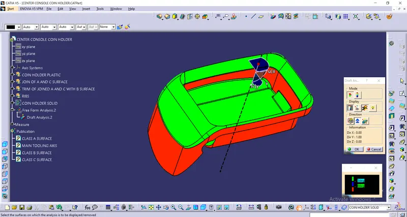
NOTE: Since there is error in Class A surface Draft analysis will not qualify the required criteria so will infirm the higher authorities to class change the Class A surface.
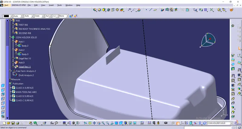
After creating the solid body we move to the Rib Creation.
We extract the surface were we want to make the rib and draw the sketch then perform the pad, add the rib to the main part then provide the required fillet.
NOTE: THE RIB IS CREATED KEEPING ALL THE DESIGN ASPECTS OF THE RIB.
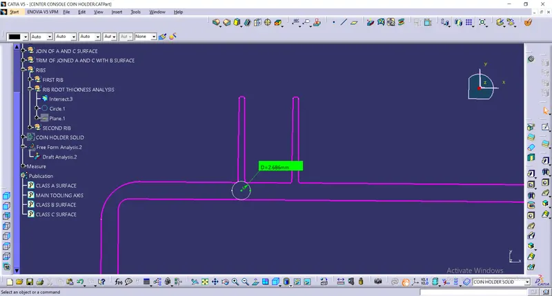
Rib root thickness analysis:
Initially we intersect the part were we want to do the Rib root thickness analysis.
We perform Rib root thickness analysis by drawing tritangent circle and reducing the 3D accuracy propotionality and measuring using vernier calliper and confirming the value in the constrain.
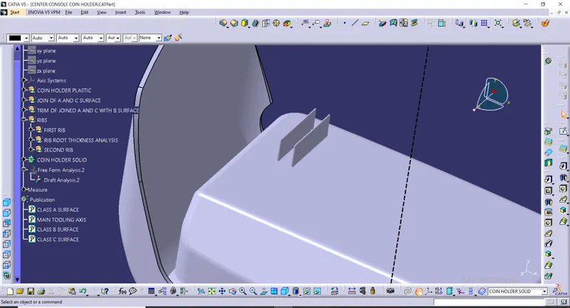
Now Create the next Rib similarly keeping the design in mind.
EXPLANATION ON BISECTING METHOD:
Bisecting method is basically use to find the proper tooling axis using the dummy tooling axis. In Bisecting method, bisecting line is used which either bisect the two line or it will show error which means the two lines are parallel to each other. In order to know whether the particular surface is toolable or not we intersect the surface with the respective plane and get a sketch which consist of two lines and with the help of bisecting line option we bisect the line which creates a line at the mid point of the two lines. Like wise we create tooling clearing axis for x and y which will be used to create the main tooling axis using the bisecting line option in in the line comand.
Performing draft analysis on the final component:
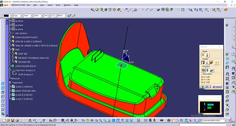
Screenshots of the completed design in various orientations:
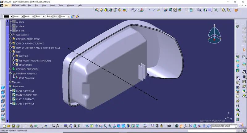
ISOMETRIC VIEW:
FRONT VIEW:
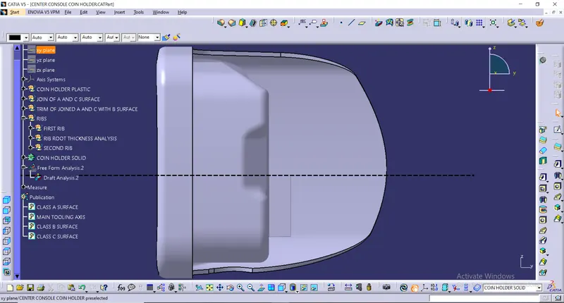
SIDE VIEW:
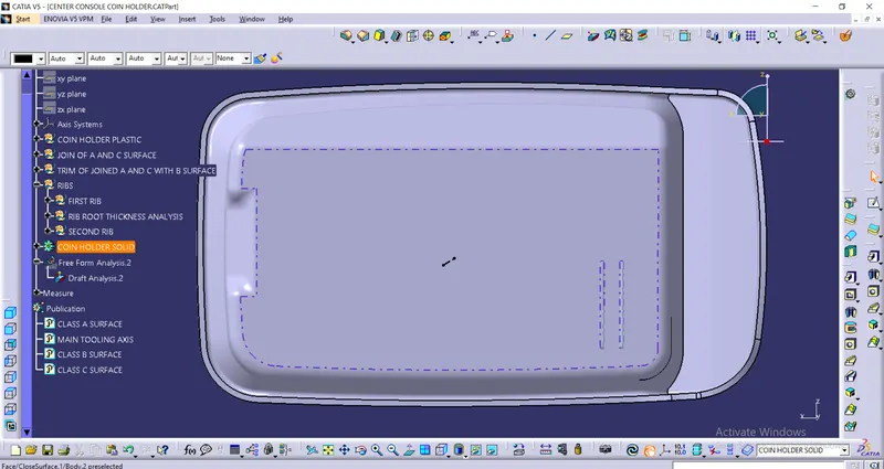
TOP VIEW: