Week 10 - Challenge 3 - Door Trim Lower with Engineering Features
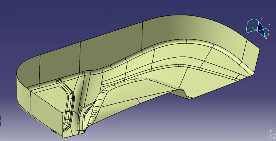
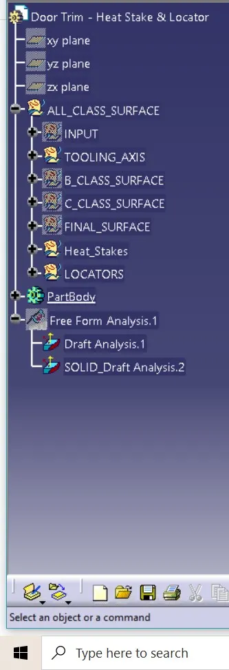
We have to first make the solid body from the class A surface.
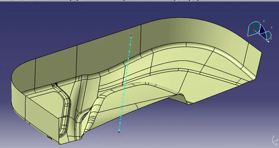
We should be start with the first with create with the tooling axis for creating the tooling axis we have select the edge which are to be create the issue for the draft or plastic mold.
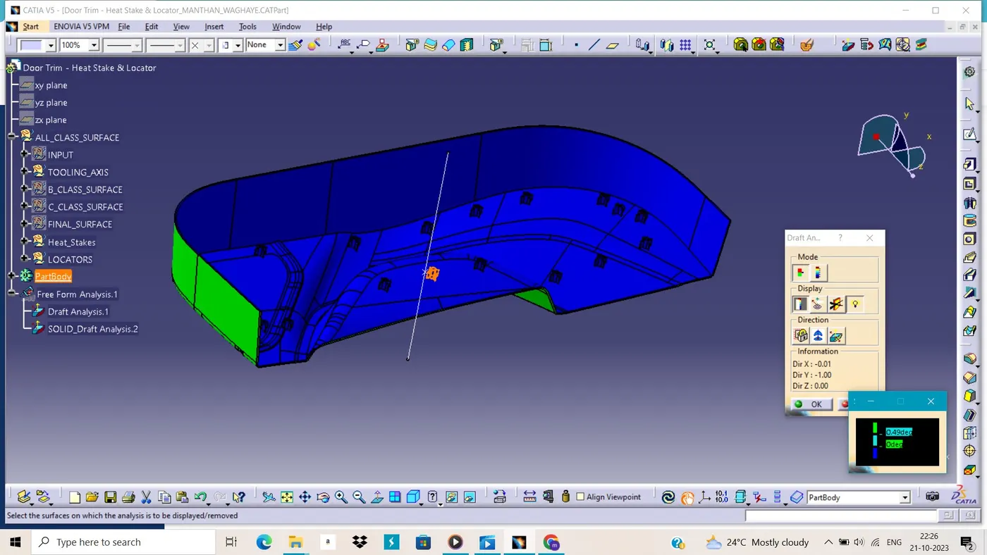
So, we have to do the draft analysis for the plastic mold so we have to analyse the part for creating the dummy axis and then we have to create the bisecting line from this edge. due to the complex surface, we can direct take the side on which the part can be taken out.
<!-- [if !supportLineBreakNewLine]-->
<!--[endif]-->
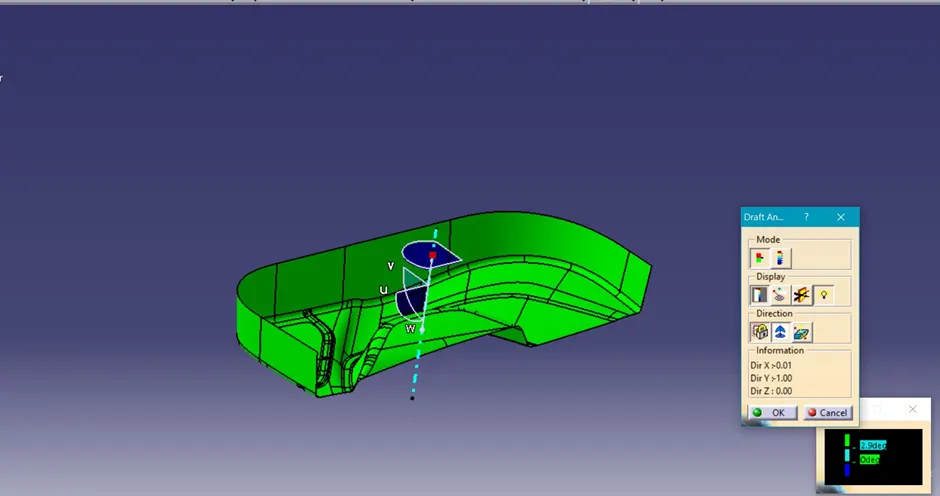
Here this tooling axis can be used to see the draft analysis.
<!-- [if !supportLineBreakNewLine]-->
<!--[endif]-->
After the creating the tooling axis we have to creating the B surface from the A surface so we extract the surface as wall and base surface for the fillet are not easy to make
For making the B class surface we have to extract the plane surface and untrim and extrapolate them so that they can be intersect and then we can trim them as one surface and then we have to offset at thickness as here 3mm.
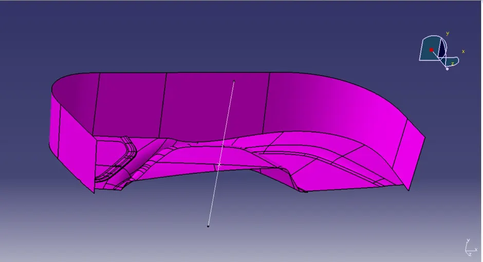
Then we have to fillet it but when we are giving the fillet radius, we have to consider this fillet value add or subtract it by the part thickness or not.
After creating the B surface, we have to create the C surface from the edge which are closed or the closed the surface and then we have to trim the B surface with the C surface and then join the A surface and trim surface and then we get the final surface of base bracket for the creating the C surface we have to use the boundary and the multiple extract tool to get the edge to create the surface.
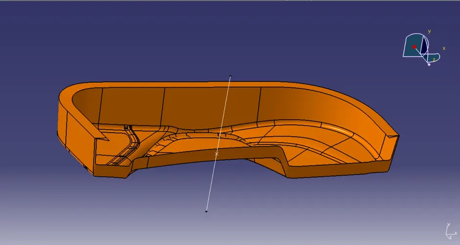
When we trim the surface with the Class A surface with the C surface and then with the B Surface and get the Final surface.
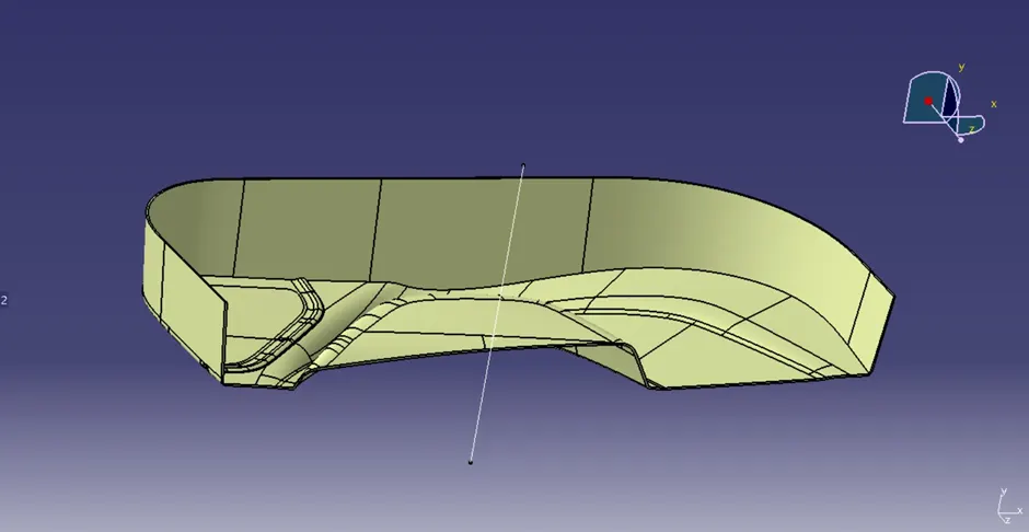
After that we have to create the thick surface in the part design workbench before that we have to check the surface is closed or not then we create the thick surface.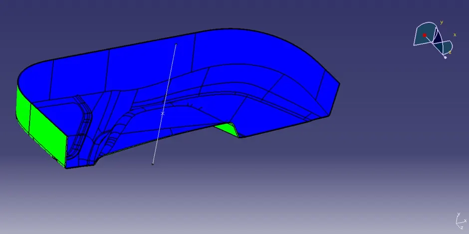
In draft analysis we can see the green and blue colour which so the green means draft more than the 3° and blue for draft minus.
Heat staking
Then we have to create the heat stakes on the B surface which are not seen by customer or part.
It is an engineering element used in the creation of plastic trim.
Heat staking :- In manufacturing products with thermoplastic components it is often necessary to join a thermoplastic to part of dissimilar whether it be metal a dissimilar plastic or other material.
General Description :- Thermal staking is an assembly method that uses the Controlled melting and reframing of plastic stud or boss to capture of lock another plastic of metal of assembly in place the plastic stud products an through a hole in Component to be locked in place the heated thermal tip contacts the top stud which melts and fills the volume of the tip cavity to produce head locking the Component in place.
The progressive melting of plastic under continuous pressure from the head when staking the sight combination of heat and pressure for the application of critical.
Heat staking is the process to attach two separate components together by melting the base plastic material into a shape that will hold the secondary component. It’s a permanent attachment method that does not require any additional material such as an adhesive or a solvent to make the permanent bond. The only addition is the heat applied to melt the plastic and a tool to shape the plastic to form the mechanical connection. Heat staking can be done with a precise and rapid operation that also offers repeatable results every cycle. Manufacturing machine can be developed to complete multiple heat staking operations at once to decrease cycle time. The stakes don’t have to be parallel which makes the design options limitless. Heat staking is a great option that is comparable in strength and durability to other operations involving secondary fasteners without extra cost. These connections can also resist corrosion in harsh environments.
Advantages -
→ Simplification of machinery.
→ Reduced cost of machinery.
→Multiple fastening points.
→Allows higher density of welds compared to hot air cold frame of ultrasonic welding.
2-WAY LOCATORS:
A 2-way locating pin restricts motion along 1 axis (or 2 degrees of Freedom), like a round pin in a slot. Likewise, a 4-way pin restricts 4 degrees of freedom along 2 axes. A round locating pin located concentrically in a hole is a common application of a 4-way pin, and helps to further secure the piece.
4-WAY LOCATORS:
4-way mean you prevent movement at 2 axis (+X, -X, +Y and -Y) on the plane. Generally, you have cylindrical pin on the fixture and circular hole at workpiece part.
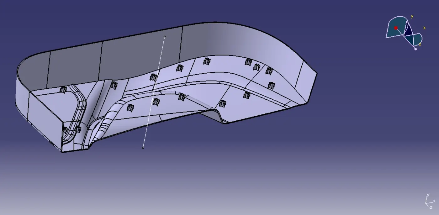
CONCLUSIONS: The 4 way and 2-way locators, heat stakes has been created following all the plastic design guidelines.