Week 10 - Challenge 2- Attachment Feature Creation (Dog House)
Aim:
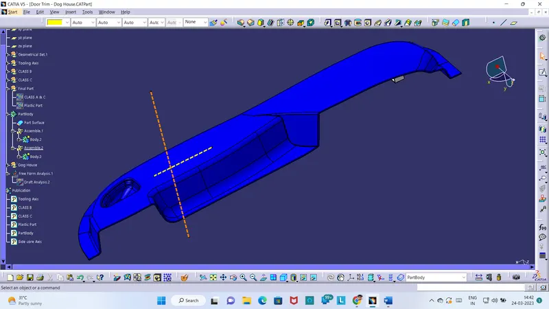
Creation of the Dog House for the Door Trim considering the design rules.
Constructional Report:
Tooling Axis:
- The direction in which the Mold or core and cavity opens is the tooling axis.
- For Tooling axis creation, need to find the flat surface, extract it and create the point in its centre by Reference tool Bar. Create new Geometrical set as Tooling axis.
- Then Create a Line through the point on Y Direction and extend it & highlight the line as per our convenience
- Put the Class A surface in No material Mode in View tool bar.
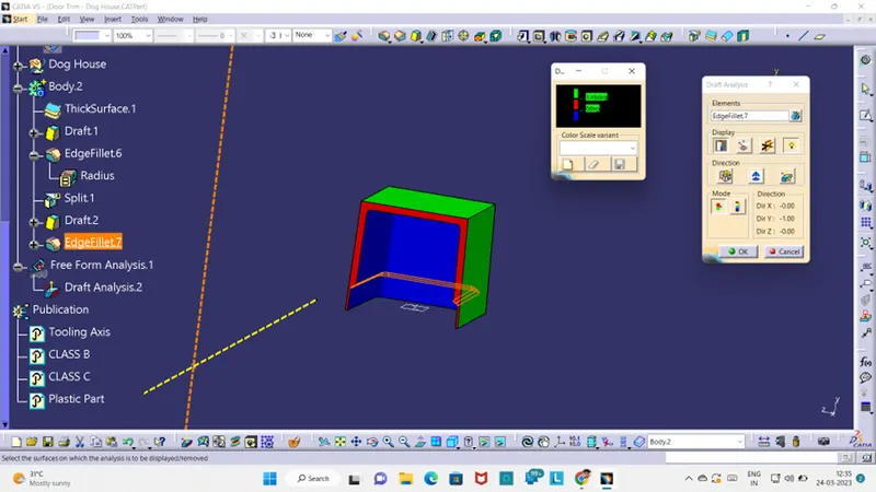
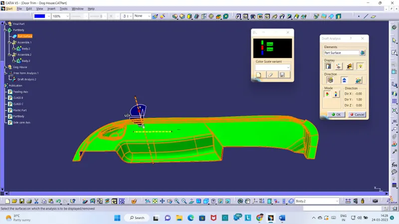
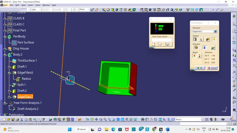
- Go to Insert - > Analysis - > Feature Draft Analysis.
- Click the Compass, drag the compass towards that line and place vertically along it and click lock button.
- Select on any part of the surface then see some colour changes on it.
- Select 3 degrees as green and check the surface it shows all as green, it means our created tooling axis is correct.
- In this orange Colour line indicates the Tooling axis.
CLASS B:
- Create new Geometrical set as Class B
- CLASS B surface having all Engineering features likes ribs, Screw Bosses & Dog House.
- For this we need Class A surface and need to Offset it as per given Thickness 2.5 mm.
- After Offsetting check the non-off-setted patchy surfaces, here we used to join command because we had patches in it filleted areas so those fillets are removed from the offset surface.
- Take boundaries and extrapolate that and make a trim.
- Then measure the fillets radius from class B surface & do fillets on those edges we did trim. If you measure fillet radius from class B (Offset surface) we can directly use those values. But if you measured from CLASS A means reduces the material thickness with fillet value.
- Now we created the CLASS B Surface.
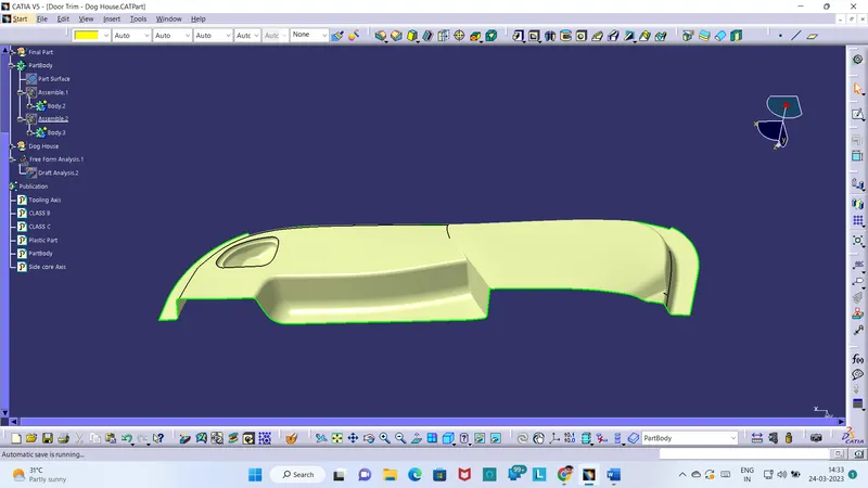
CLASS C:
- CLASS C surface provides the connectivity as already thickness we provided on class B surface with Class A surface.
- Create a New geometrical set as CLASS C.
- If our class C surface want Parallel to tooling axis means use the draft direction angle method.
- If our Class C surface want in perpendicular tooling axis means use the reference surface method.
- In Our design all sides want a parallel CLASS C surface, so we did creation with draft direction sweep method.
- Then join those sweeps and extrapolate in it edges wherever needed.
- Do the trimming operations to get full body as a CLASS C surface in single surface.
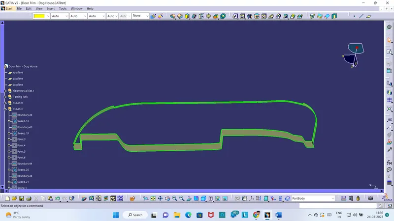
CLASS A & C:
- Now we have separate CLASS A & CLASS C surfaces. Create new Geometrical set.
- So now we can join those class A and class c surface by using join command and give 0.003mm, which is the maximum deviation value we can provide to surfaces.
- After CLASS C surface we saw some boundaries along the joined surface. So we did rework on sweeps in CLASS C command where we give upper limits, for giving enough contact with class A & C surfaces.
- So here we trimmed the two surfaces because of additional material over from Class C.
- Now we have closed CLASS A & C surface.
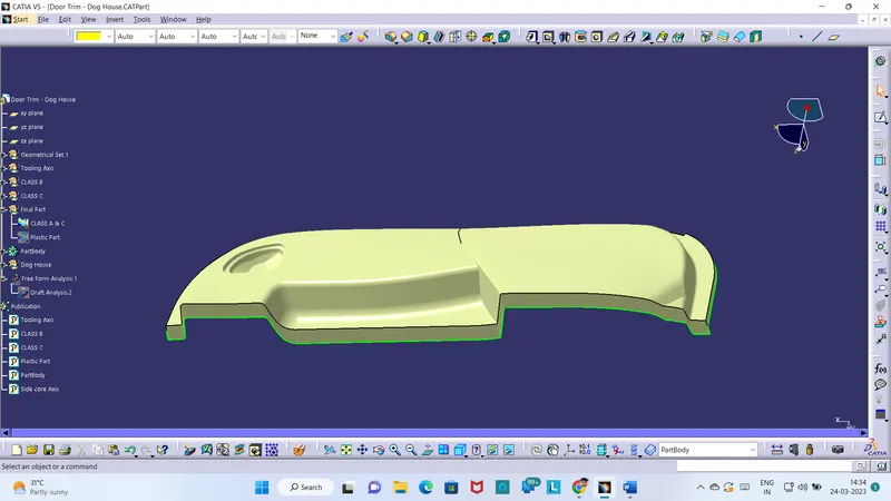
PLASTIC PART & FINAL PART:
- Now trim our class A & C with class B surface to get the desired part. Create new Geometrical set.
- Then define the part body and go to part design workbench, where select the close surface.
- Select our final part, now thick part body gets created.
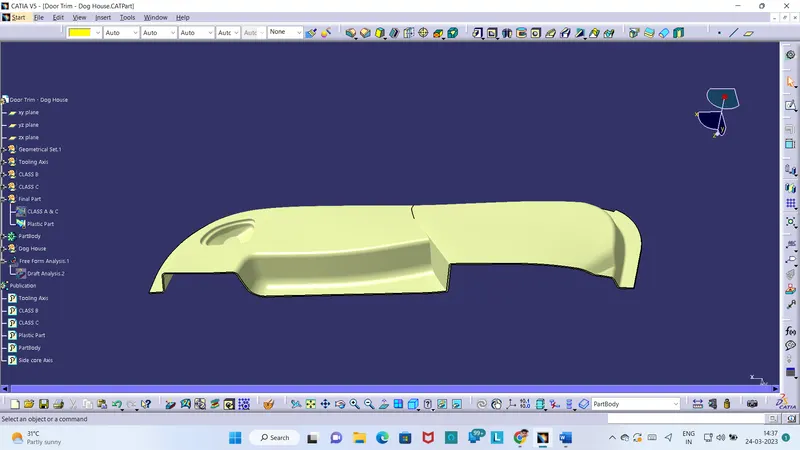
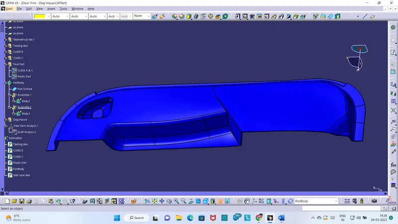
DOG HOUSE:
- Dog house is secondary Class B side Engineering feature.
- Using for engagements one part with another part and also having some engineering features.
- New Geometrical sets was created as Dog house, where we created a point & plane for sketching.
- Do sketching the rectangle and constraint it.
- Then sweep the sketch with respect to the tooling axis at 1.5-degree draft direction & limit of 22mm.
- Offset the top surfaces for getting closed surface.
- Then convert the surface into thick surface at 2 mm, now fillet the edges with 3 mm later we can change.
SIDE CORE AXIS:
- Side core axis also a type of Tooling Axis, we can say it is additional tooling axis for sub elements on our part body in different axis.
- Here we used the axis for inside clearance for dog house part.
- Inside walls of dog house was drafted with those side core axis at 0.5 degrees draft angle with pilling direction of the same.
- Now offset the inside wall to 1mm because we must have inside wall thickness minimum 0.4 times of material thickness. So, our material thickness is 2.5 (2.5 X 0.4 = 1 mm).
- Then offset from the base to 4mm because the height range between 3mm to 6mm.
- Now trim those intersecting surfaces and we got bottom part for splitting operation.
- Go to Part body, split the trim part & give draft angle of 0.5 degree to inside of cutter face.
- Fillet those sharp edges of 1mm & assemble our part to main part body.
- Do copy the same part body and paste special ,then translate that copied part to our desired place by using coordinates.
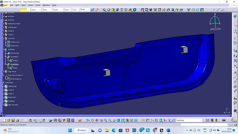
Publication:
- Publication is a future used to represent our specific surface or body outside from our mingled tree.
- It is mainly used to represent bodies for easy selection purposes.
- All surfaces are published as well for the same.
Tree Structure:
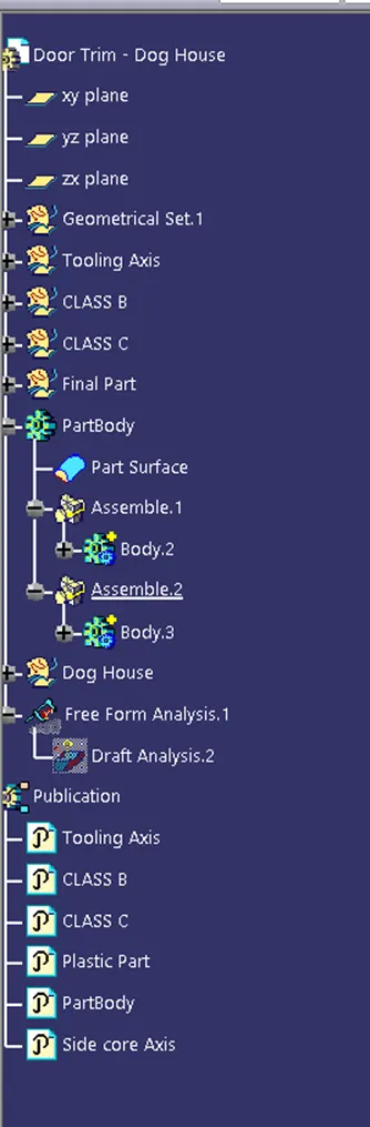
RESULT:
- The Dog house were created and published as per the standards where the screenshot’s part files are attached with these reports for further reference.