Week 10 - Challenge 3 - Door Trim Lower with Engineering Features
Aim:
Creation of the Ribs, Locaters and Heat stakes for the Door Trim considering the design rules.
Constructional Report:
Tooling Axis:
- The direction in which the Mold or core and cavity opens is the tooling axis.
- For Tooling axis creation, need to find the flat surface, extract it and create the point in its centre by Reference tool Bar. Create new Geometrical set as Tooling axis.
- Then Create a Line through the point on Y Direction and extend it & highlight the line as per our convenience
- Put the Class A surface in No material Mode in View tool bar.
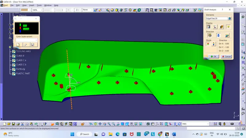
- Go to Insert - > Analysis - > Feature Draft Analysis.
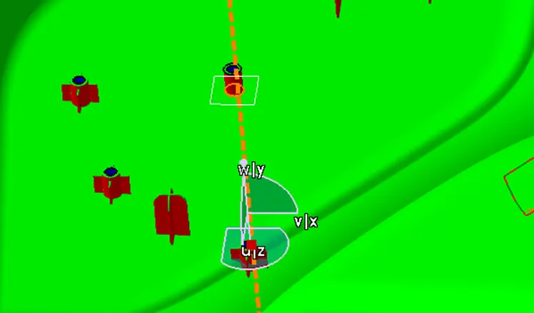
- Click the Compass, drag the compass towards that line and place vertically along it and click lock button.
- Select on any part of the surface then see some colour changes on it.
- Select 3 degrees as green and check the surface it shows all as green, it means our created tooling axis is correct.
- In this orange Colour line indicates the Tooling axis.
CLASS B:
- Create new Geometrical set as Class B
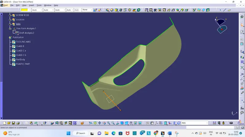
- CLASS B surface having all Engineering features likes ribs, Screw Bosses & Dog House.
- For this we need Class A surface and need to Offset it as per given Thickness 2.5 mm.
- After Offsetting check the non-off-setted patchy surfaces, here we used to join command because we had patches in its filleted areas so those fillets are removed from the offset surface.
- Take boundaries and extrapolate that and make a trim.
- Then measure the fillets radius from class B surface & do fillets on those edges we did trim. If you measure fillet radius from class B (Offset surface) we can directly use those values. But if you measured from CLASS A means reduces the material thickness with fillet value.
- Now we created the CLASS B Surface.
- As per our convenience we can extrapolate the B surface ,it will useful while trimming with CLASS C Surface.
CLASS C:
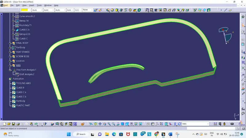
- CLASS C surface provides the connectivity as already thickness we provided on class B surface with Class A surface.
- Create a New geometrical set as CLASS C.
- If our class C surface want Parallel to tooling axis means use the draft direction angle method.
- If our Class C surface want in perpendicular tooling axis means use the reference surface method.
- In Our design front sides want a parallel CLASS C surface, so we did creation with draft direction sweep method.
- Bottom & middle we want a perpendicular surface, so we did creation with reference surface method.
- Then join those sweeps and extrapolate in it edges wherever needed.
- Do the trimming operations to get full body as a CLASS C surface in single surface.
CLASS A & C:
- Now we have separate CLASS A & CLASS C surfaces. Create new Geometrical set.
- So now we can join those class A and class c surface by using join command and give 0.003mm, which is the maximum deviation value we can provide to surfaces.
- After CLASS C surface we saw some boundaries along the joined surface. So we did rework on sweeps in CLASS C command where we give upper limits, for giving enough contact with class A & C surfaces.
- So here we trimmed the two surfaces because of additional material over from Class C.
- Now we have closed CLASS A & C surface.
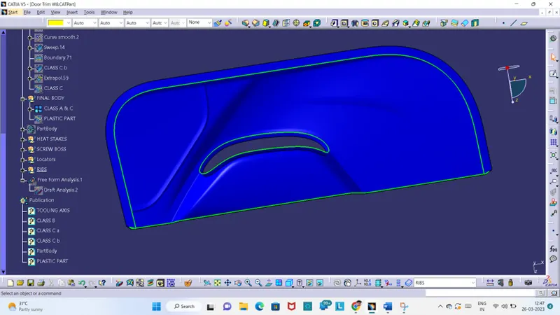
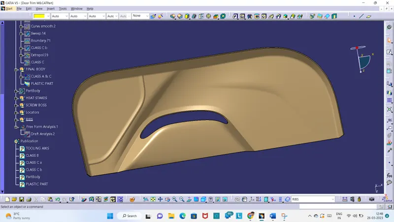
PLASTIC PART & FINAL PART:
- Now trim our class A & C with class B surface to get the desired part. Create new Geometrical set.
- Then define the part body and go to part design workbench, where select the close surface.
- Select our final part, now thick part body gets created.
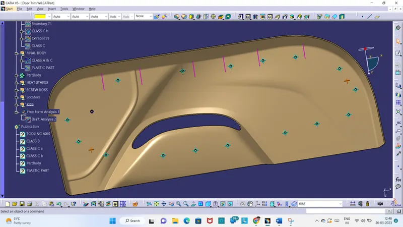
RIBS:
- Now we have final part body, create a plane over the surface where we want to create ribs.
- Create a point on the surface for projection purpose.
- Create new Geometrical set and define it & select position sketch take plane as planar support & select point as a projection point in origin & reorder the orientation.
- Sketch the ribs line and provide proper dimensions, make sure the sketch is iso constraints.
- Select the Pad option and pad it 5 mm height up to 5t thickness of our part. Our part has 2.5 mm thickness so 5 X 2.5 =12.5 mm. Provide second limit also as 1mm inside our body, thick profile is selected as well and give 1mm as thickness as per norms 0.4 times of body thickness we can give for neutral thick body 2.5 X 0.4 =1 mm.
- Give draft angle as 0.5 degrees and select neutral element as base plane pulling direction as Tooling axis.
- Assemble it to our part body tree
- By using these procedures, we create other ribs also and fillet those ribs of 25 mm as per norms.
- Now our Ribs are created.
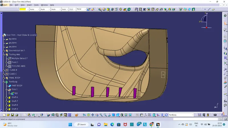
SCREW BOSS:
- Create new Geometrical set and define it & select position sketch take plane as planar support & select point as a projection point in origin & reorder the orientation.
- Sketch the Screw boss and provide proper dimensions inside dia 5.2 bolt size & onside of wall should 0.6 times of thickness so (0.6 X 2.5 X 2 = 3mm) and add bolt thickness (5.2 + 3 = 8.2 mm) outside dia, make sure the sketch is iso constraint it.
- Pad it for 12 mm and secondary limit of 1mm inside the part body.
- Fillet the bottom part of 0.25mm radius.
- Then Create the supports of this screw boss need to create.
- Select position sketch take plane as planar support & select point as a projection point in origin & reorder the orientation.
- Create a line inside the middle and constrain it, dimensions of 20mm per line (10 +10) on both the directions in horizontal direction.
- Also, for vertical direction same line was created.
- Define in new part body and Pad It for 10mm height, secondary limit of 1mm & neutral thickness of 1mm.
- Give draft angle as 0.5 degrees and select neutral element as base plane pulling direction as Tooling axis.
- Make a union trim with Closed part body and remove the inside element.
- Finally provide fillets of 0.25mm for all edges.
- Copy the part file and make a paste special with link as result.
- Move the part body wherever we want by using translation method and select coordinate option in translation.
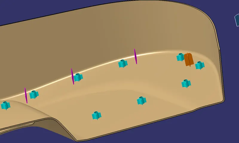
Locators:
- Locators are another type engineering featured part.
- It is used for arresting the degrees of freedom in some direction with respective to its places we did it.
- Also, it acts as guiding part, to engage nearest part with it.
- The dimensions are similar to ribs principle.
- We did it in two places over the door trim part.
- We created one part and translated into another place by using coordinate parts.
- Then we trim it with the main part.
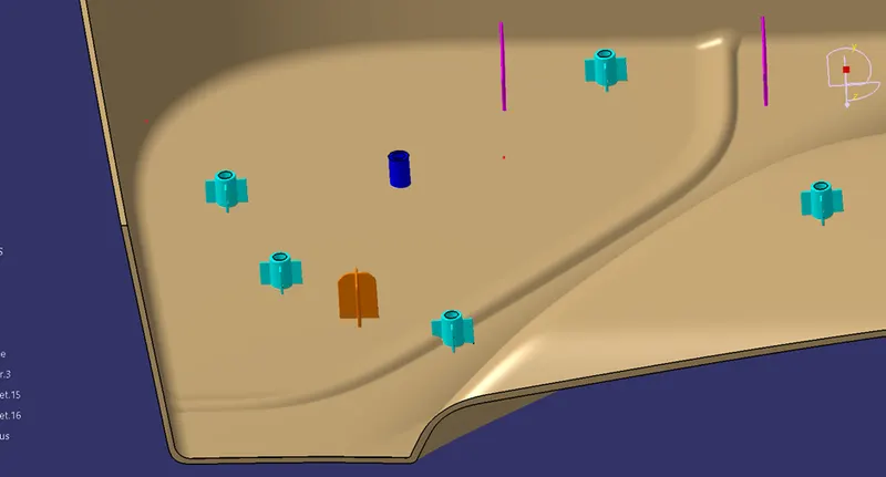
Heat Stakes:
- Heat stakes are another type of engineering featured part.
- It is used for fixing with another part. In some words, it is called plastic welding.
- When we heat that and it melts, gets fix with parent or children part.
- The dimensions are similar to ribs principle.
- We did it in one place with the basic dimensions.
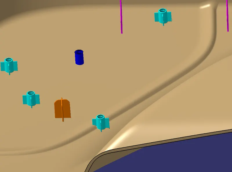
Publication:
- Publication is a future used to represent our specific surface or body outside from our mingled tree.
- It is mainly used to represent bodies for easy selection purposes.
- All surfaces are published as well for the same.
TREE STURCTURE:
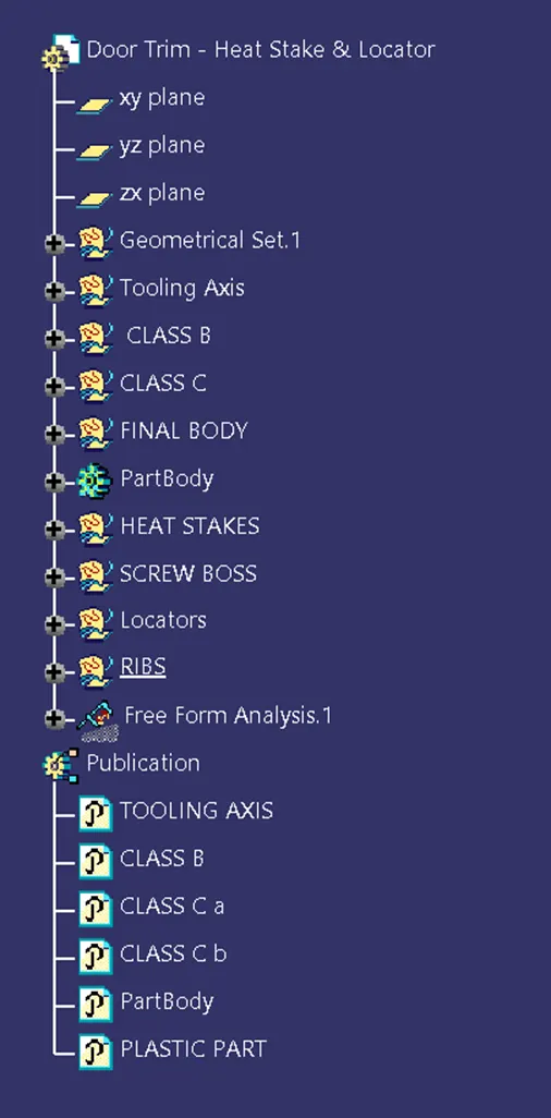
RESULT:
- The Dog house were created and published as per the standards where the screenshot’s part files are attached with these reports for further reference.