Fender Design
FENDER
Aim:
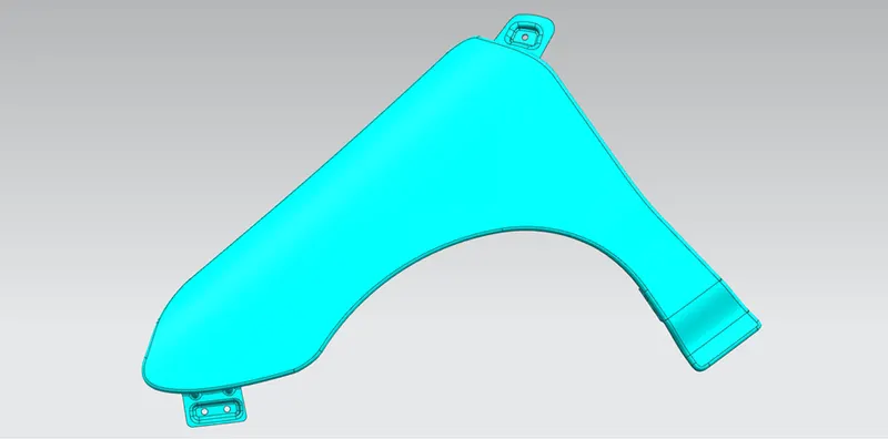
Design a fender by using input class A surface, design Drip area by using a given master section as a reference, and add various mountings like Sill mount, Bumper mount, and A pillar mount.
What is Fender:
A fender is the part of a car that protects and frames its wheels and keeps mud from splashing it. Most modern vehicles have fenders on their front wheels. When you get into a minor car accident, you can call it a "fender bender," and it's possible that your fenders did get slightly dented
Sometimes we can make provision for indicators and rear-view mirror on the fender
Types of Fenders:
1.Full Fender
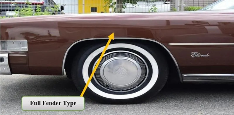
2.Half Fender

Important areas considering while fender Design:
- Drip Area
- Bumper mounting area of a fender
- Sill mounting area
- A pillar mounting area
- Baffle mounting area
- Drip Area
- Drip Area is the area through which the fender is mounted inside the engine Compartment.
- It having some standards specifications we need to consider while designing this area such as from A pillar mounting there should be minimum 200 mm clearance should be there for Cowl top (wiper motor) mounting area.
- The height of the drip mount should not be greater than 40mm to avoid spring back effect and NVH concerns.
- These parameters are following by all OEM brands so ,we should consider while designing this area.
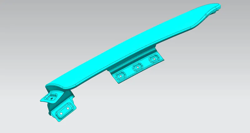
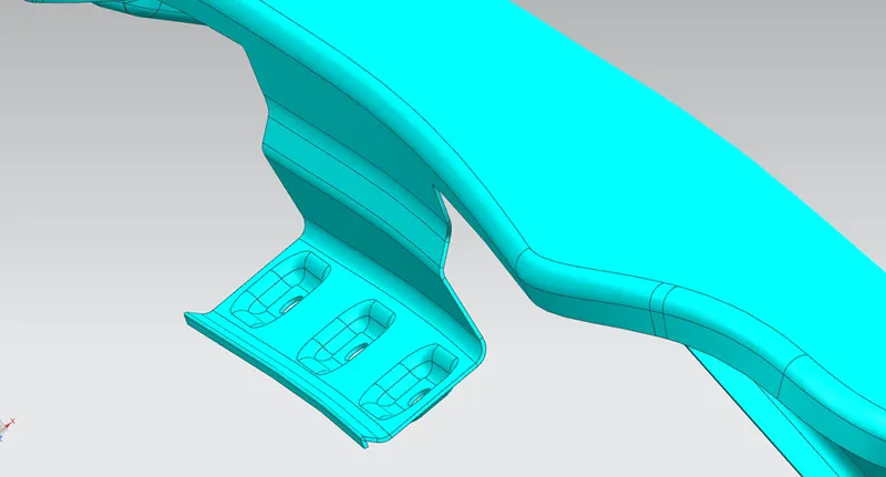
- Use Law extension to extend the sheets for required length, direction and angle.
- Sketches are created and emboss is done by use datum planes.
- Finally, holes are created by using trim sheets.
- The Hole should be 5mm flat surface around the hole.
- Blends are provided as per the master section given.
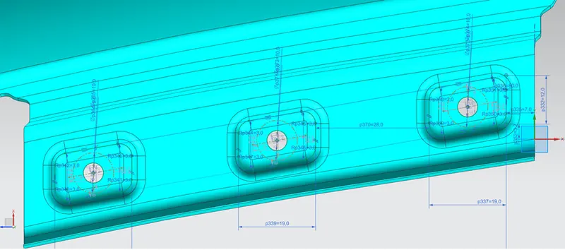
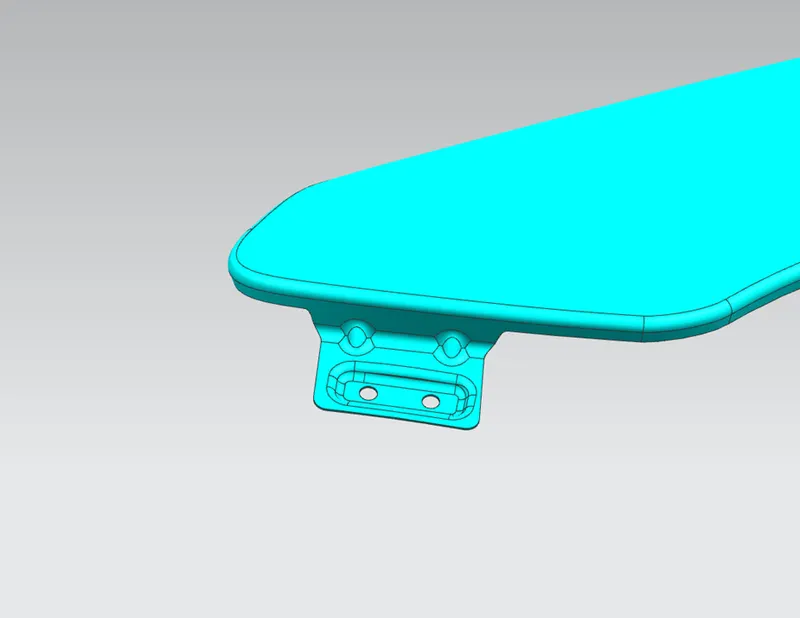
- Bumper mounting area:
- This mounting connects with bumper portion.
- Law extension commands are used and sketches and plane are created for embossing purpose.
- For getting a flat surface we used emboss as a datum plane, then we offset that for our required depth and trimmed the hole.
- Bridge curves are used for getting smooth surface corners.
- Dart operation is used for creating stiffener like surface for providing enough strength to the flange.
- Sill mounting area:
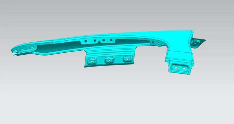
- This portion is connected at bottom of the car and near to the door.
- Extend sheet command is used for sheet extension.
- Datum plane and sketches are created and emboss is done by using the same datum plane for getting flat surface.
- Bridge curve and Trim Sheet operation are used for getting smooth edges.
- A pillar mounting:
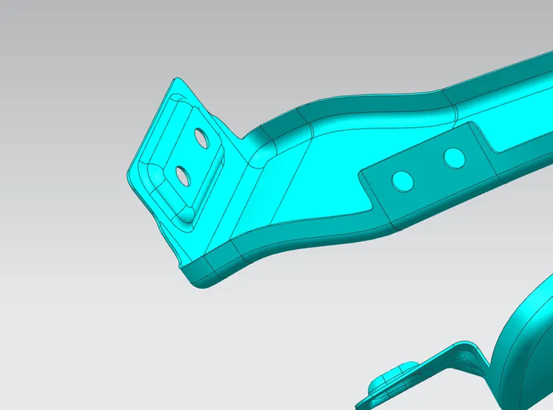
- This area is fixed near to the A pillar Portion and near to cowl top mounting area where this mounting is fastened with A pillar.
- Same curve of surface profile sheet is trimmed and law extension.
- Datum plane and sketches are created and emboss is done by using the same datum plane for getting flat surface.
- Bridge curve and Trim Sheet operation are used for getting smooth edges.
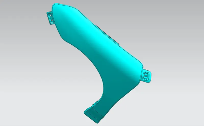
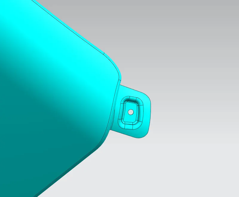
- Baffle mounting area:
- This Area is place at wheel arch portion, it is bottom portion over the type face.
- In this area baffle is mounted with the clips, baffles used to prevent road debris going in to the engine bay and doors.
- By using bridge curve option, we trimmed required as per required portion and sketches are done.
- Then holes and curves are trimmed for holding clips arrangements and clearance to avoid stress concentration.
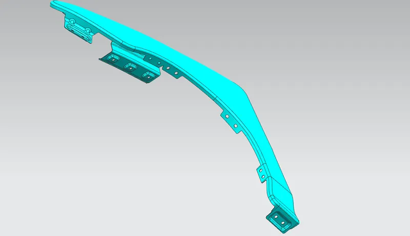
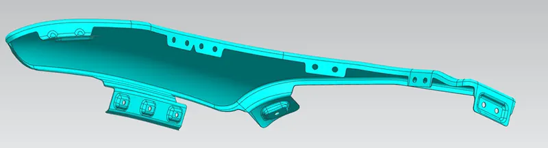
Conclusion:
We Created fender mountings ares, and created drip area by using master section provided.