Hood design-Week 2
AIM:
Design a hood with the given input data to satisfy the engineering, manufacturing and functional requirements.
HOOD:
Hood is basically one type of door which is used to close the engine compartment. Hood basically consists of two main parts: inner panel and outer panel where inner panel gives strength to the outer sheet and outer sheet is just a sheet with curves for aesthetic purpose.
COMPONENTS IN HOOD:
- Inner Panel
- Outer Panel
- Stricker
- Hinge Mechanism
- Mastics
INNER PANEL:
- Inner Panel is the main component in Hood Assembly. It is not like an aesthetic.
- It is having some other parts like Sticker, Embosses, Hinges and Mastics.
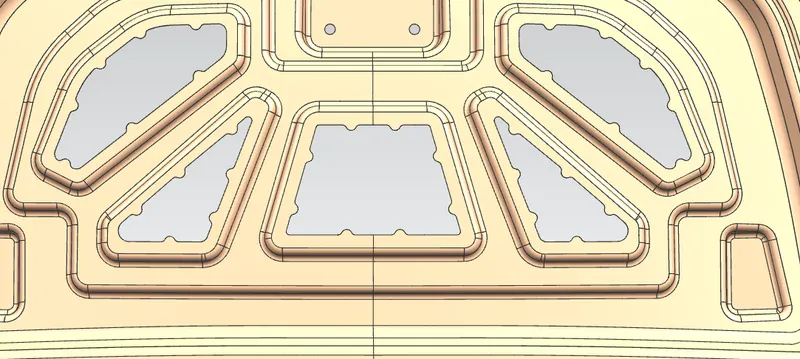
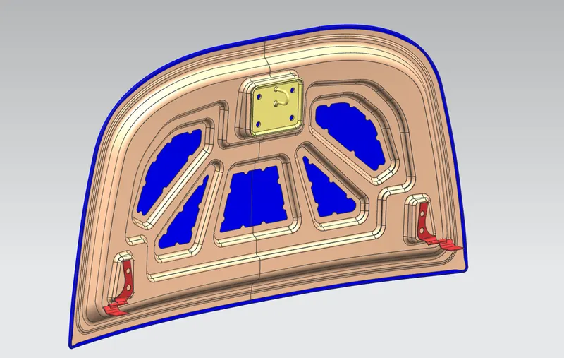
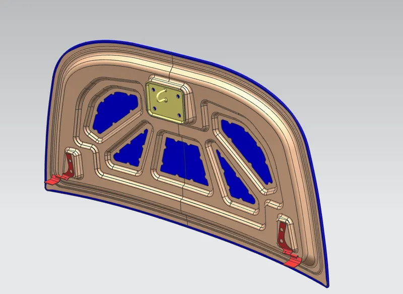
- Inner panel consists of various types of embossed to get strength. It also has various cut-outs for mounting and holding purposes like cut-outs for support rod or gas stay etc.
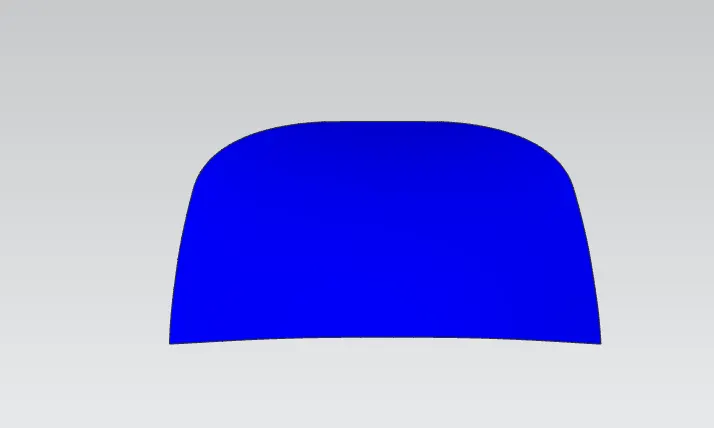
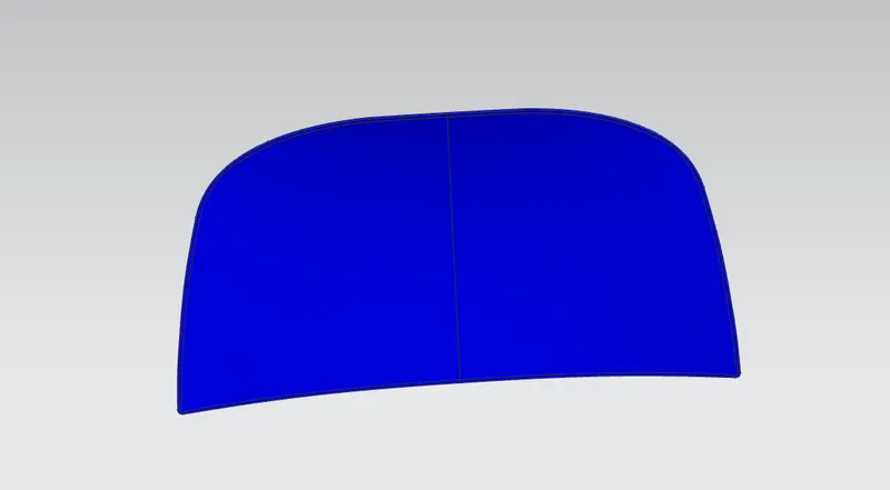
OUTER PANEL:
- Its purpose is to give aesthetic look as well as the shape and inclination with respect to the windshield of outer hood is such that the aerodynamic drag is minimum as possible.
- As a BIW designer we need to give strength to the outer surface without disturbing its shape.
STRICKER:
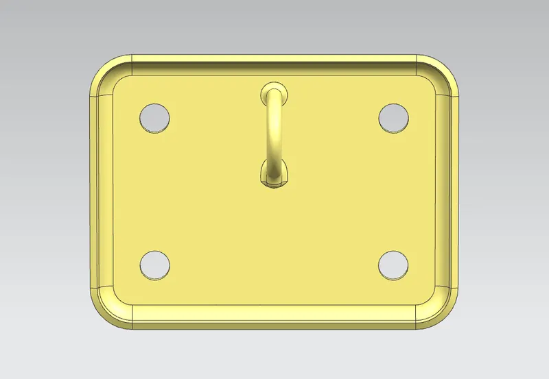
- In simple stricker is the one part for locking mechanism which helps to lock the hood to the engine front compartment.
- Stricker is also the standard part which mounts on the inner panel of the hood and the other part of the locking mechanism is mounted on the engine bay.
- Like hinges we need to give certain height and angle. The main criteria to mount the stricker on the inner panel is that the axis of the stricker must be tangent to the rotational curvature of the inner panel.
HINGES:
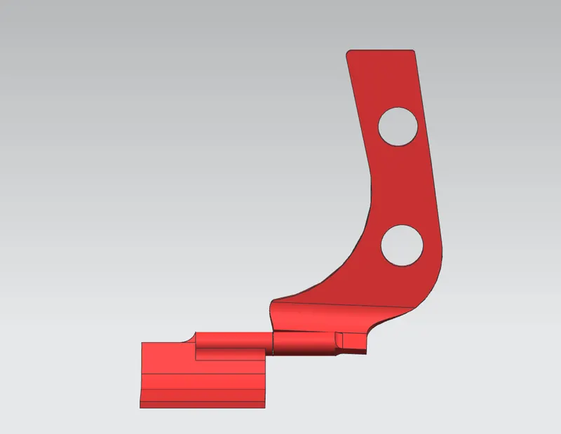
- Hinges are the standard parts used in the hood assembly; the main purpose of hinges is to give opening and closing to the hood.
- The one side of the hinge is mounted on the engine compartment and the other side is mounted on the hood.
- The axis of 2 hinges must be the same in trajectory of Stricker.
- Based on the hinge position we need to do embosses to the inner panel of the hood.
MASTICS:
- Mastic seal is basically the Glue used between the outer panel and inner panel. We can apply a mastic seal where we need to provide stiffness.
- Mastic seals help with noise and vibration cancellation.
- The mastic seal gives stiffness in 80mm diameter.
STAY ROD:
- The basic application of a stay rod or gas stay is to hold the hood in open position. Stay rod is the rod with a slightly bended in shape to get good strength and can Provide support to the hood when it is in an open position.
- The bend should not be more than 35mm.
- Similar to the stay rod gas stay is used.
Design consideration for hood:
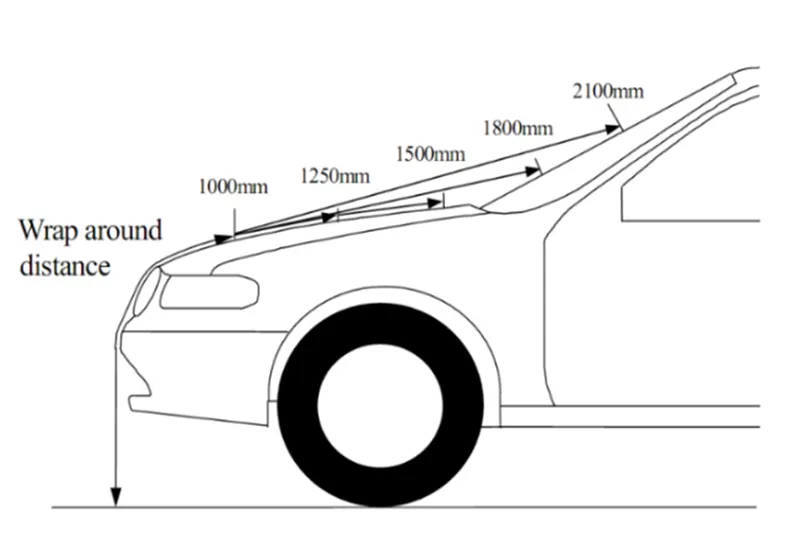
- WRAP AROUND DISTANCE:
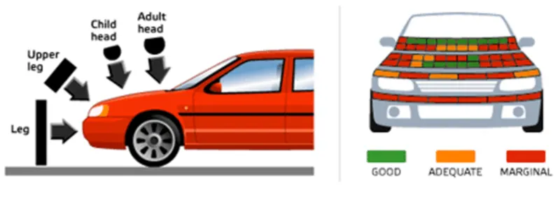
- In pedestrian-car accidents, head injuries are a common cause of death. The acceleration of the head's centre of gravity (henceforth, head centre) resulting from a head hit is used to determine the HIC (Head Injury Criterion) value, which is a measure of the mortality risk of a head injury.
- During the majority of pedestrian-vehicle collisions, the pedestrian's entire body wraps around the car's front form. This has an effect on the vehicle's head impact. Meanwhile, the windscreen is a significant impact point that has undergone NCAP testing.
- Car contact speed, vehicle type, rigidity and shape, nature of the front (such as bumper height, bonnet height and length, windscreen frame), pedestrian age and body height, and standing posture of the pedestrian relative to the vehicle front all influence the degree of injuries. One of the most essential parameters for assessing pedestrian protection is the Wrap Around Distance WAD.
- HOOD OPENING ANGLE:
- The angle at which hood is opening should be sufficient that it should not strike the person who is checking the engine. the opening angle varies region to region it is basically depends on the average height of the person.
- Placement of Mastic Seal
- The mastic seal gives stiffness in 80mm diameter. Glue is used to hold the inner panel with the outer panel and it for arresting the noise while driving.

Input Data:
Hemming Data:
Relief rear Section:
Front relief:
Major Commands used for designing of hood in NX:
- Offset surface
- Offset curve on surface
- Trim sheet
- Through curve
- Law extension
- Emboss
- Face blend
- Edge blend
Special features of hood inner panel:
Emboss: It is used to increase the stiffness of the inner panel technically increase the section modulus and also dissipate force towards hinges we primarily choose the polygon shape of emboss to get better control over the collapsibility of hood.
Cut out: This gives the ability of collapsibility of Hood so that the impulse does not transfer to the pedestrian and occupants.
Reinforcement: This is used to give the strength locally, here it is used for striker and hinge portion.
Construction:
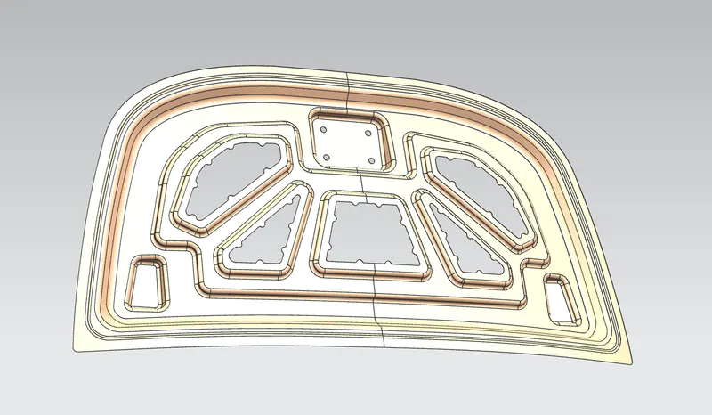
1.Inner Panel:
- Flanges:
- Given Class A surface is offseted as per the Master section given.
- By using through curve option, we created the curve towards inside as per the distance given.
- Trimmed those surfaces with the through curves by using trim command.
- Then the edges are blended by using face blend option.
- Embosses:
- We Created the sketch for base emboss by some calculation from master section.
- The height is given as 10 mm from the vector as tooling axis at an angle of 12 degree.
- Over the base emboss some 3 sketches are created for arresting the impact while collision.
- Then sketches are embossed for 8.5 mm by the same tooling axis and angle one by one we given below earlier.
- Cut outs:
- In the 3 embossed faces some are made with cut outs and mastics at 10mm.
- Then the profile is projected and trimmed.
- Face blends are given 6mm in all faces.
- Trajectory:
- Sketch is created and projected into the surface then emboss that with respect to the datum plane for height.
- Then assembly Constraints are given with axis to axis and face to face.
- By creating mirror feature with respect to plane.
- Create a point on the hinges in both sides then create a line, create a datum plane in between.
- Do sketch in that plane like hood trajectory circle, horizontal line and angled line with that circle at intersection.
- Constrain the angled line and intersection point with the striker as the same portion.
- Reinforcement:
- For Hinges and stricker position we created reinforcement by extracting the faces and law extension and sew it.
- Then trimmed with our main surface as well, now if we changed the angle of trajectory correspondingly the stricker will move respectively.
- Then do the edge blends with the surface.
- Then sharp edges are trimmed at one side and mirrored into another side.
2.Outer Panel:
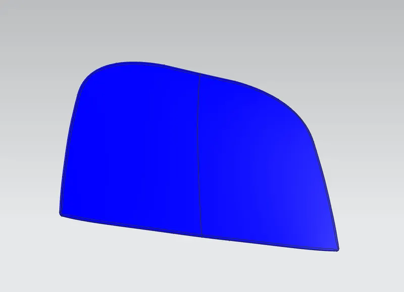
- Hemming:
- Surface is offseted into 6.25 mm (0.75+2+0.75+2+0.75) as per master section.
- Curves faces is offseted inside 6mm and 1mm.
- Then law extension the 1mm curve with the vector option.
- Three face blend is done with offseted, law extension and main surface.
- Reliefs are provided with bridge curves and curve on face as per the master section provided.
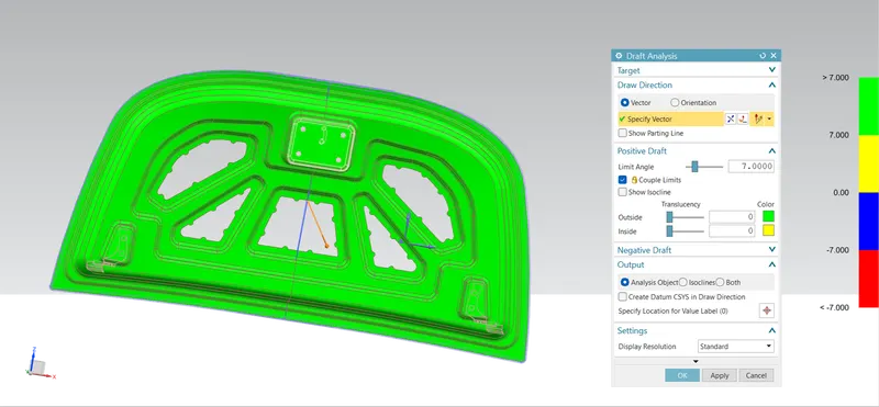
Draft analysis:
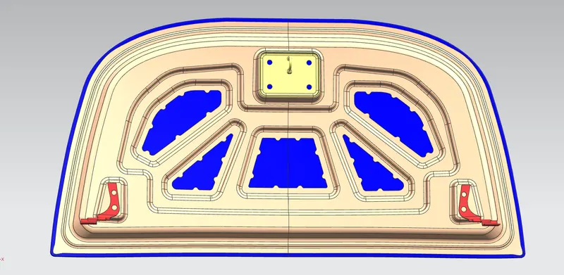
- It is a tooling direction where how the core and cavity open and ejection of sheet metal from the system.
- Draft analysis is checked with 7 degrees, all areas are cleared by the tooling axis we used earlier.
Section Modulus:
It is the ratio between area moment of inertia to the distance from neutral axis to outmost fibre.
Z = I / y
Bending Equation M / I = σ /y = E / R
where I = Moment of Inertia,
E = Young's modulus
σ = Stress at any fibre at a distance of y from the neutral axis,
M = Bending moment and
R = Radius of curvature.
Z = Section Modulus
So, M = (I x σ) ⁄ Y
In simple words bending moment is how much deformation is happening in our Component, when we applying load.
Bending moment is directly proportional to the area moment of inertia, here our Y length of our neutral axis is constant. If area moment of inertia is increased, bending moment will increase as well.
Why we are calculating Bending Moment and Section Inertia Analysis?
Now we are creating Hood, so we need to know how much impact resistance it has and how much it can withstand while collusion with another. As a design engineer we should consider the engineering aspects for design of Hood. So, we are calculating the Bending moment and Section Inertia Analysis report for comparing our report with our parent design or other competitor’s design.
How I did the section modulus calculation?
- Mid line is created on our surface by using this perpendicular datum plan is created.
- By using intersecting option, we did intersection with it together.
- Now we got outer boundary of our design surface.
- Sketching is done because it was having some patches, so we joined those lines together.
- Now we got a closed surface, for doing section inertia analysis we need only the closed surface.
- Analysis is done we got Minimum moment of inertia for our design is shown below.
- Then Again we did offset from the intersection sketch 0.5 mm, then again analysis is done that also attached below and its calculations as well.
Initial Analysis
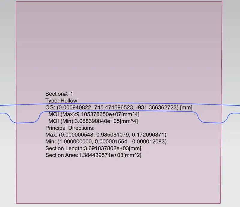
I1 = 3.088390840 X 105 mm4
Y1= 438.27 mm
|
Z1 = I1/Y1 => 704.67 mm3 |
Offsetted Profile:
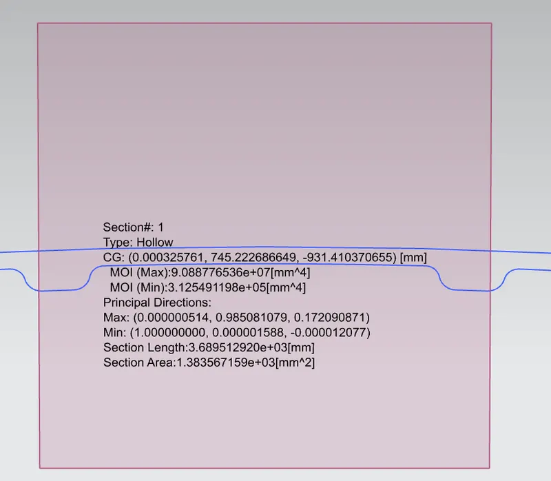
I2 = 3.125491198 X 105 mm4
Y2= 438.27 mm
|
Z2 = I2/Y2 => 713.2 mm3 |
Z2 > Z1
Conclusion:
We have designed the Hood and inertia analysis, if we increased the cross-sectional area inertia is increasing. So, moment of inertia is proportional to the Section modulus.We can get high inertia when we considering Cross section.