Week 12- Final project
Aim:
Development of a Door Trim panel by using Master Sections of considering the design rules.
Construction:
- In our Door Trim Project contains four major parts. They are listed as follows.
- Arm Rest
- Lower Substrate
- Map Pocket
- Bottle Holder
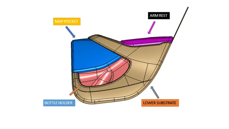
ARM REST
An arm rest offers the possibility of comfortably positioning your hand when driving on a motorway or standing in traffic, yet not only. Depending on the equipment of an individual vehicle, it can also combine the functions of the control console of the vehicle’s electrical systems and the practical storage compartment. Car armrests are manufactured from a variety of materials, including a hard plastic base, a soft foam top, and an outer pad. All these components should provide comfort of use, durability, stability and safety.
Class-A Surface:
- In automotive design, a class A surface is any of a set of free form surfaces of high efficiency and quality. It gives the aesthetic of the component which is created by the styling team and gives to the part design engineer to create the part with all engineering aspects.
- Taken class A surface for Arm Rest from given Class A surface. When checked continuity of the class A surface it’s not smooth one corner.
- So, making smooth I have done some modification on that corner. Finally, we have got class A surface.
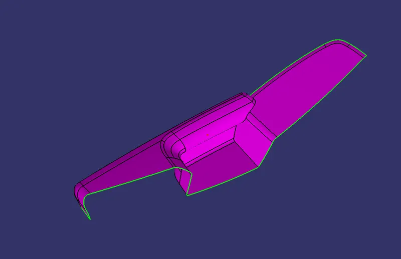
Tooling Axis:
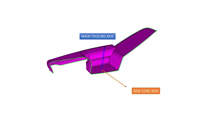
- The direction in which the Mold or core and cavity opens is the tooling axis.
- For Tooling Axis Creation, here we used the bisecting method.
- We have used the lines which are created using reference from its adjacent walls.
- Create a point in between the first two lines, then create a bisecting line with respect to the point.
- Do the same process with another angle in another two lines and create the main tooling axis.
- Put the Class A surface in No material Mode in View tool bar.
- Go to Insert - > Analysis - > Feature Draft Analysis.
- Click the Compass, drag the compass towards that line and place vertically along it and click lock button.
- Select on any part of the surface then see some colour changes on it.
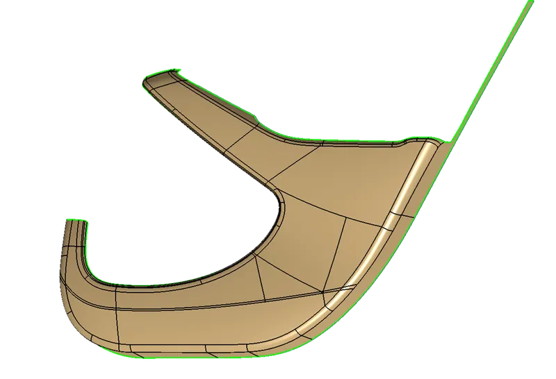
- Select 3 degrees as green and check the surface it shows all as green, it means our created tooling axis is correct.
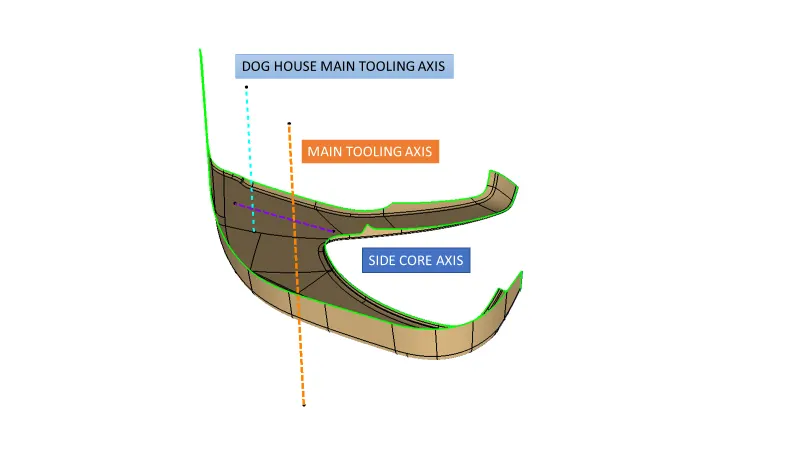
- Here some portions are not cleared so we introduced new side core axis ,which is perpendicular to main tooling axis.
CLASS B:
- Create new Geometrical set as Class B
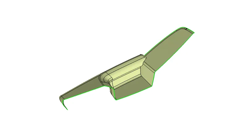
- CLASS B surface having all Engineering features likes ribs, Screw Bosses & Dog House.
- For this we need Class A surface and need to Offset that so create a new geometrical set and offset it as per given Thickness 2.5 mm.
- After Offsetting some patch in it, so extract the side boundaries then make that as a smooth curve.
- Then do sweep with reference surface.
- After the patchy surface rework, check the boundaries on green which is in smooth finish not having any errors in the surface.
- Take Overall Boundary of Class B surface and extrapolate it 3 to 5 mm as per our convenience.
- Go to extrapolate tool in Operations tool bar, select the boundary and put in curvature continuity.
- Now we created the CLASS B Surface.
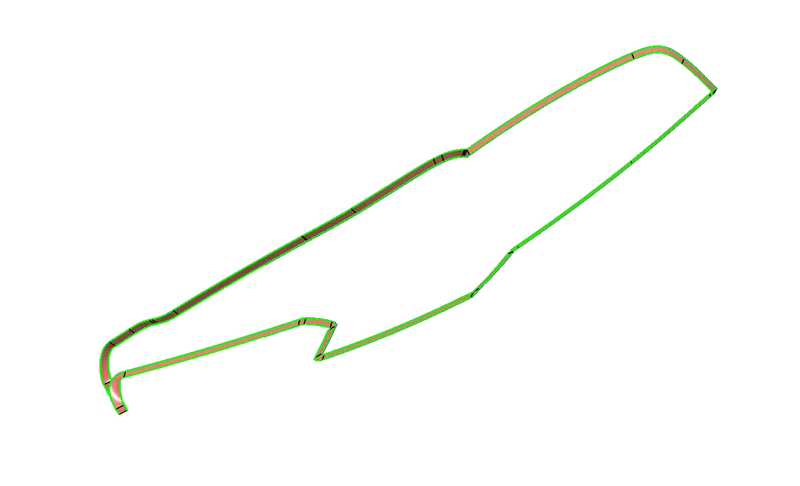
CLASS C:
- CLASS C surface provides the connectivity as already thickness we provided on class B surface with Class A surface.
- Create a New geometrical set as CLASS C.
- If our class C surface want Parallel means use the draft direction angle method.
- If our Class C surface want in perpendicular means use the reference surface method.
- We need to do create class C surface for two sides so using draft direction in sweep.
- Select the boundaries of two sides and select sweep option then select draft direction option.
- Select the curve and guiding tooling axis and give the value how much depth we want that curve for intersect our class B Surface.
- For perpendicular creation, so we used reference method. Take another two sides boundaries & make a sweep as per our required depth.
- Then join those sweeps and extrapolate in it edges wherever needed.
- Do the trimming operations to get full body as a CLASS C surface in single surface.
CLASS A & C:
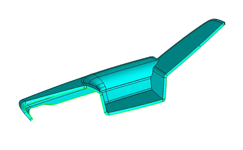
- Now we have separate CLASS A & CLASS C surfaces. Create new Geometrical set.
- So now we can join those class A and class c surface by using join command and give 0.001mm, which is the maximum deviation value we can provide to surfaces.
- We have joined those surfaces now next will be trimming operation
PLASTIC PART /FINAL PART:
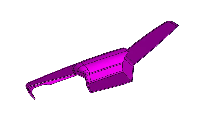
- Now trim our class A & C with class B surface to get the desired part. Create new Geometrical set.
- Then define the part body and go to part design workbench, where select the close surface.
- Select our final part, now thick part body gets created.
Engineering Features:
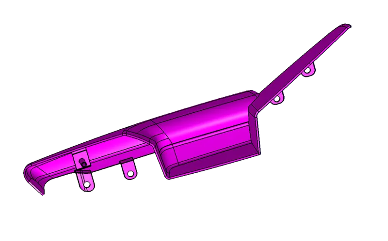
- Now we have the solid body, now we want to create some engineering features, they are listed as follows,
FLANGES:
- Flanges are the features using for keeping screw boss from another part body with our main part body.
- Create new Geometrical set and define it & select position sketch take plane as planar support & select point as a projection point in origin & reorder the orientation.
- Sketcher where we have the master section. We can project it at one face and make it as a construction element.
- Then sketch over the reference lines then exit from the sketch.
- Now extract the edges as per our required portion.
- Then do sweep with profile as our sketch and guide curve as our Extracted elements. We got surface now.
- Now we added a part body and went to part Design workbench then did thick surface of 2.5 mm.
- Then copy the body and do paste special as a result.
- Create the straight line and extrude it against our sweeper surface. Then do offset in both the directions of 10mm, here our flange width we taken as 20mm.
- By using solid split tool, we splitted that flange on both sides.
- Now repeat the same process in our pasted bodies as per space we required and do same splitting operation.
- Finally, five flanges are created, now need to do draft of 1.5 degrees with main tooling axis.
- Edge fillets are provided on outer faces, then it is assembled in single part body and added to our main part body.
- Then remaining fillets are provided, now we can do the draft analysis.
- Separate draft analysis report is attached to with this report kindly find that as well.
HEAT STAKE HOLES:
- Extract the flange surface and make a point in its middle surface.
- From Lower Substrate Heat stakes take that hole as reference and make a sketch of hole in flange of 8.5 mm circle then constrain it as concentricity.
- Pocket that hole and remove it from our main Part Body.
- Same process is followed for other flange holes also.
- Then do draft as well of 1.5 degree with the main tooling axis.
- Now we were provided fillets as well.
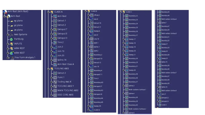
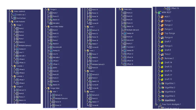
Tree Structure:
LOWER SUBSTRATE
- In Door panel, lower substrate is the main part which is holding other parts were surrounded it, having the Heat Stakes which keeps the nearest part with it through flanges.
- Lower Substrate is the encapsulating aesthetic Part used in the door panel. It may house various features such as Wirings, Speakers and other sheet metal components behind it.
CLASS A:
Tooling Axis:
- The direction in which the Mold or core and cavity opens is called tooling axis.
- For Tooling Axis Creation, here we extracted the flat surface from CLASS A and create a point in middle.
- Then Perpendicular line was created with respect to that point.
- Put the Class A surface in No material Mode in View tool bar.
- Go to Insert - > Analysis - > Feature Draft Analysis.
- Click the Compass, drag the compass towards that line and place vertically along it and click lock button.
- Select on any part of the surface then see some colour changes on it.
- Select 3 degrees as green and check the surface it shows all as green, it means our created tooling axis is correct.
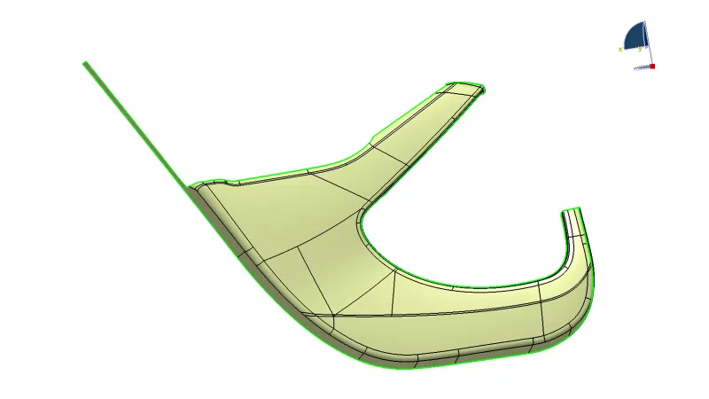
CLASS B:
- Create new Geometrical set as Class B
- CLASS B surface having all Engineering features likes ribs, Screw Bosses & Dog House.
- For this we need Class A surface and need to Offset that so create a new geometrical set and offset it as per given Thickness 2.5 mm.
- After Offsetting some patch in it, so extract the side boundaries then make that as a smooth curve.
- Then do sweep with reference surface.
- After the patchy surface rework, check the boundaries on green which is in smooth finish not having any errors in the surface.
- Take Overall Boundary of Class B surface and extrapolate it 3 to 5 mm as per our convenience.
- Go to extrapolate tool in Operations tool bar, select the boundary and put in curvature continuity.
- Now we created the CLASS B Surface.
CLASS C:
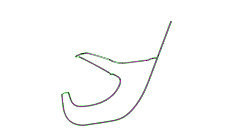
- CLASS C surface provides the connectivity as already thickness we provided on class B surface with Class A surface.
- Create a New geometrical set as CLASS C.
- If our class C surface want Parallel means use the draft direction angle method.
- If our Class C surface want in perpendicular means use the reference surface method.
- We need to do create class C surface for two sides so using draft direction in sweep.
- Select the boundaries of two sides and select sweep option then select draft direction option.
- Select the curve and guiding tooling axis and give the value how much depth we want that curve for intersect our class B Surface.
- For perpendicular creation, so we used reference method. Take another two sides boundaries & make a sweep as per our required depth.
- Then join those sweeps and extrapolate in it edges wherever needed.
- Do the trimming operations to get full body as a CLASS C surface in single surface.
CLASS A & C:
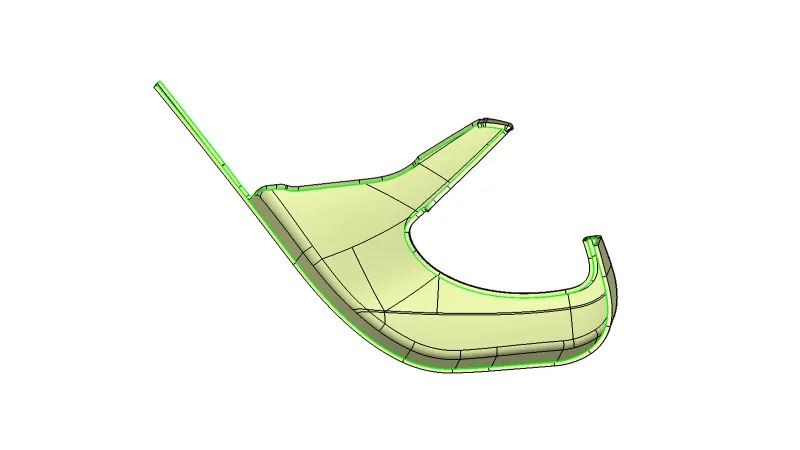
- Now we have separate CLASS A & CLASS C surfaces. Create new Geometrical set.
- So now we can join those class A and class c surface by using join command and give 0.001mm, which is the maximum deviation value we can provide to surfaces.
- We have joined those surfaces now next will be trimming operation
PLASTIC PART /FINAL PART:
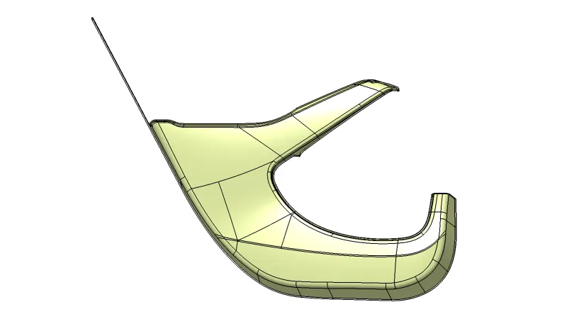
- Now trim our class A & C with class B surface to get the desired part. Create new Geometrical set.
- Then define the part body and go to part design workbench, where select the close surface.
- Select our final part, now thick part body gets created.
SCREW BOSS:
- Create new Geometrical set and define it & select position sketch take plane as planar support & select point as a projection point in origin & reorder the orientation.
- By using parallel curve option, we created a parallel curve inside the lower substrate walls for heat stakes base.
- Points are created for heat stake projection point by using Master Section.
- Select position sketch take plane as planar support & select point as a projection point in origin & reorder the orientation.
- Take the reference from master section and sketch measure the diameter between those master sections. Inside dia 4.5 mm & Outside 7.5mm respectively.
- Define in new part body and pad it to 25 mm as per the master section.
- Then draft in provided 1.5 degree to both inside & outside by main tooling axis as reference axis.
- For providing support to heat stakes four-way locator support is created 15 x 15 mm by sketch using same plane & point as we already used for heat stake.
- Define in new part body and Pad It for 10mm height, secondary limit of 1mm & neutral thickness of 1mm.
- Give draft angle as 0.5 degrees and select neutral element as base plane pulling direction as Tooling axis.
- Make a union trim with Closed part body and remove the outside elements.
- Finally provide fillets of 0.25mm for all edges.
- Copy the part body and paste special as result with link as per our required quantity.
- Move the part body wherever we want by using translation method and select Point to Point in translation.
- By using same method, we created, copied & pasted in many places for keeping and holding the flanges of other parts.
- Finally, fillets are provided on base of the heat stakes.
Dog House:
- Dog house is secondary Class B side Engineering feature.
- Using for engagements one part with another part and also having some engineering features.
- New Geometrical sets was created as Dog house, where we created a point & plane for sketching.
- Do sketching the rectangle and constraint it.
- Pad it 30mm and shell at 2.5 mm, Outside faces are extracted and drafted at 1.5 degree.
- Fillets are provided as 3mm on its corners, offset 1mm inside the extracted face.
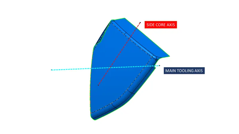
- Separate tooling axis and side core axis needed for dog house at that point in perpendicular directions.
- By parallel line is created with base surface and offset it for 5 mm upward.
- Trim our two offset surface and convert into single bottom surface.
- Make split it with our shell body, then do draft at 0.5 degree to inside walls with respect to side core axis.
- Fillets are provided inside 0.5 mm and 0.3 mm to the edges as well.
- Then our Dog House body is copied and paste special is done as result with the link.
- Now translation is done on point to point.
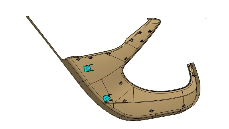
Tree Structure:
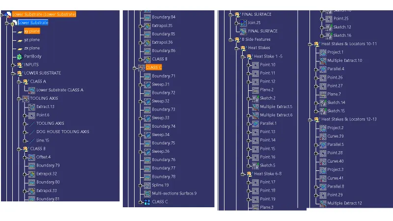
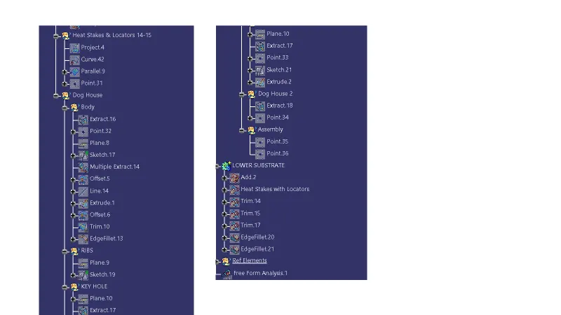
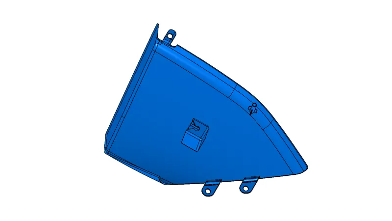
Map Pocket
- Map Pockets are generally used as storage space on the door.
- In this case The Map Pocket is divided into 2 sections the upper and Lower.
- The Upper Section acts as an enclosure from the inner parts and for aesthetics only.
Tooling Axis:
- The direction in which the Mold or core and cavity opens is called tooling axis.
- For Tooling Axis Creation, here we extracted the flat surface from CLASS A and create a point in middle.
- Then Perpendicular line was created with respect to that point.
- Put the Class A surface in No material Mode in View tool bar.
- Go to Insert - > Analysis - > Feature Draft Analysis.
- Click the Compass, drag the compass towards that line and place vertically along it and click lock button.
- Select on any part of the surface then see some colour changes on it.
- Select 3 degrees as green and check the surface it shows all as green, it means our created tooling axis is correct.
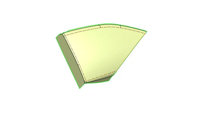
CLASS B:
- Create new Geometrical set as Class B
- CLASS B surface having all Engineering features likes ribs, Screw Bosses & Dog House.
- For this we need Class A surface and need to Offset that so create a new geometrical set and offset it as per given Thickness 2.5 mm.
- After Offsetting some patch in it, so extract the side boundaries then make that as a smooth curve.
- Then do sweep with reference surface.
- After the patchy surface rework, check the boundaries on green which is in smooth finish not having any errors in the surface.
- Take Overall Boundary of Class B surface and extrapolate it 3 to 5 mm as per our convenience.
- Go to extrapolate tool in Operations tool bar, select the boundary and put in curvature continuity.
- Now we created the CLASS B Surface.
CLASS C:
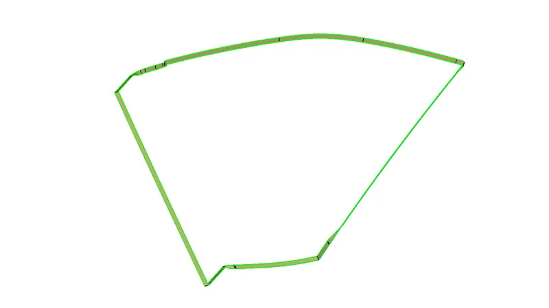
- CLASS C surface provides the connectivity as already thickness we provided on class B surface with Class A surface.
- Create a New geometrical set as CLASS C.
- If our class C surface want Parallel means use the draft direction angle method.
- If our Class C surface want in perpendicular means use the reference surface method.
- We need to do create class C surface for two sides so using draft direction in sweep.
- Select the boundaries of two sides and select sweep option then select draft direction option.
- Select the curve and guiding tooling axis and give the value how much depth we want that curve for intersect our class B Surface.
- For perpendicular creation, so we used reference method. Take another two sides boundaries & make a sweep as per our required depth.
- Then join those sweeps and extrapolate in it edges wherever needed.
- Do the trimming operations to get full body as a CLASS C surface in single surface.
CLASS A & C:
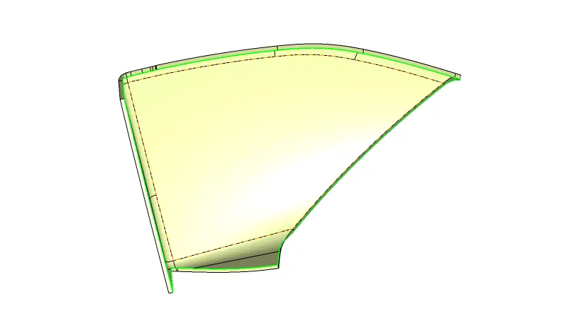
- Now we have separate CLASS A & CLASS C surfaces. Create new Geometrical set.
- So now we can join those class A and class c surface by using join command and give 0.001mm, which is the maximum deviation value we can provide to surfaces.
- We have joined those surfaces now next will be trimming operation
PLASTIC PART /FINAL PART:
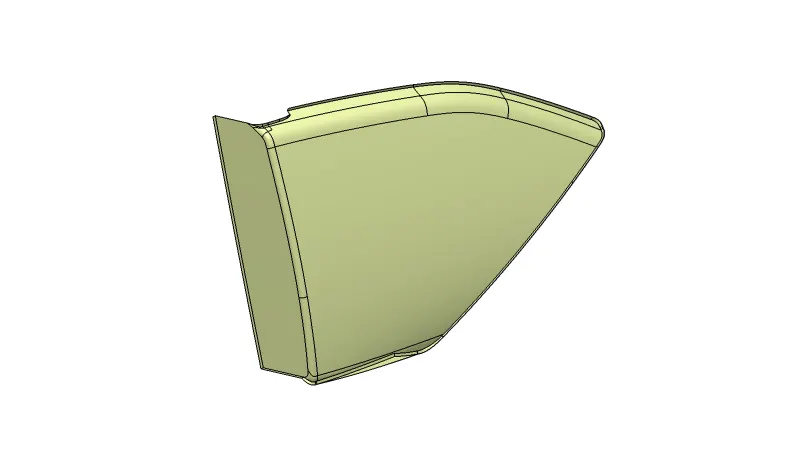
- Now trim our class A & C with class B surface to get the desired part. Create new Geometrical set.
- Then define the part body and go to part design workbench, where select the close surface.
- Select our final part, now thick part body gets created.
Engineering Features:
- Now we have the solid body, now we want to create some engineering features, they are listed as follows,
FLANGES:
- Flanges are the features using for keeping screw boss from another part body with our main part body.
- Create new Geometrical set and define it & select position sketch take plane as planar support & select point as a projection point in origin & reorder the orientation.
- Sketcher where we have the master section. We can project it at one face and make it as a construction element.
- Then sketch over the reference lines then exit from the sketch.
- Now extract the edges as per our required portion.
- Then do sweep with profile as our sketch and guide curve as our Extracted elements. We got surface now.
- Now we added a part body and went to part Design workbench then did thick surface of 2.5 mm.
- Then copy the body and do paste special as a result.
- Create the straight line and extrude it against our sweeper surface. Then do offset in both the directions of 10mm, here our flange width we taken as 20mm.
- By using solid split tool, we splitted that flange on both sides.
- Now repeat the same process in our pasted bodies as per space we required and do same splitting operation.
- Finally, 3 flanges are created by using 2 master sections, now need to do draft of 1.5 degrees with main tooling axis.
- Edge fillets are provided on outer faces, then it is assembled in single part body and added to our main part body.
- Then remaining fillets are provided, now we can do the draft analysis.
- Separate draft analysis report is attached to with this report kindly find that as well.
HEAT STAKE HOLES:
- Extract the flange surface and make a point in its middle surface.
- From Lower Substrate Heat stakes take that hole as reference and make a sketch of hole in flange of 8.5 mm circle then constrain it as concentricity.
- Pocket that hole and remove it from our main Part Body by using Boolean operations.
- Same process is followed for other flanges also.
- Then do draft as well of 1.5 degree with the main tooling axis.
- Now we were provided fillets as well.
Dog House:
- Dog house is secondary Class B side Engineering feature.
- Using for engagements one part with another part and also having some engineering features.
- New Geometrical sets was created as Dog house, where we created a point & plane for sketching.
- Do sketching the rectangle and constraint it.
- Pad it 30mm and shell at 2.5 mm, Outside faces are extracted and drafted at 1.5 degree.
- Fillets are provided as 3mm on its corners, offset 1mm inside the extracted face.
- Separate tooling axis and side core axis needed for dog house at that point in perpendicular directions.
- By parallel line is created with base surface and offset it for 5 mm upward.
- Trim our two offset surface and convert into single bottom surface.
- Make split it with our shell body, then do draft at 0.5 degree to inside walls with respect to side core axis.
- Fillets are provided inside 0.5 mm and 0.3 mm to the edges as well.
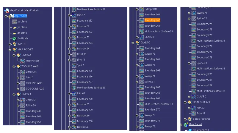
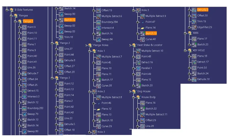
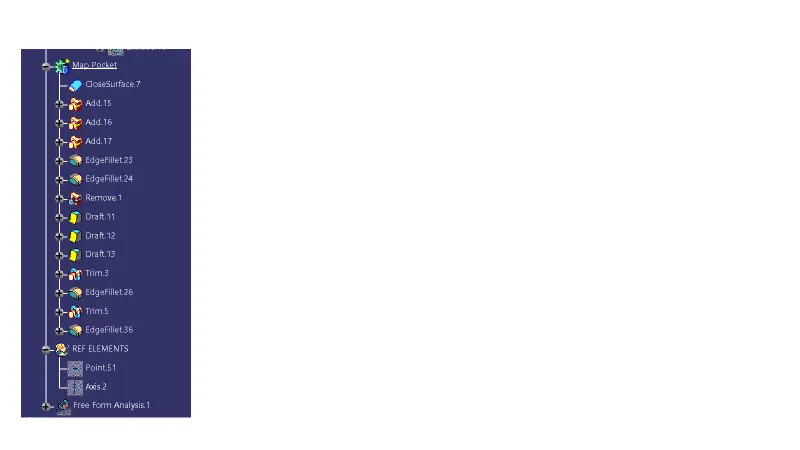
Tree Structure:
BOTTLE HOLDER
- Bottle Holder is the part in door panel, it is like a compartment for keeping bottles and space for keeping other small things.
CLASS A:
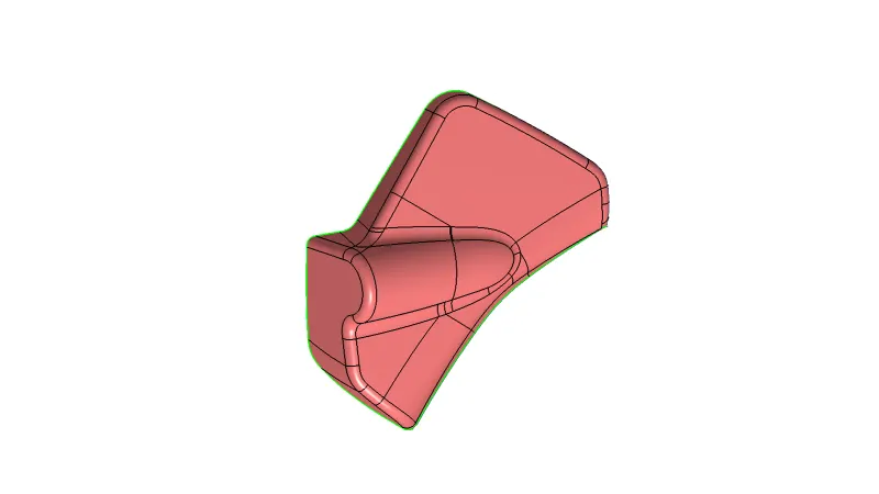
- In Automotive design, a class A surface is any of a set of free form surfaces of high efficiency and quality.
- It gives the aesthetic of the component which is created by the styling team and gives to the part design engineer to create the part with all engineering aspects.
Tooling Axis:
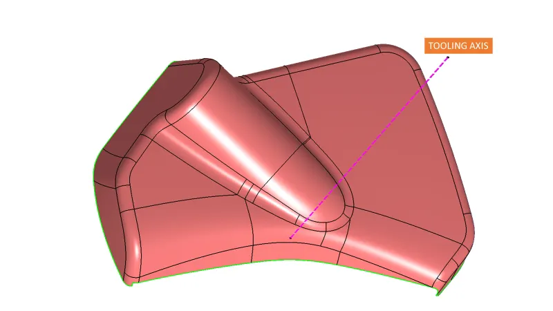
- The direction in which the Mold or core and cavity opens is called tooling axis.
- For Tooling Axis Creation, here we extracted the flat surface from CLASS A and create a point in middle.
- Then Perpendicular line was created with respect to that point.
- Put the Class A surface in No material Mode in View tool bar.
- Go to Insert - > Analysis - > Feature Draft Analysis.
- Click the Compass, drag the compass towards that line and place vertically along it and click lock button.
- Select on any part of the surface then see some colour changes on it.
- Select 3 degrees as green and check the surface it shows all as green, it means our created tooling axis is correct.
CLASS B:
- Create new Geometrical set as Class B
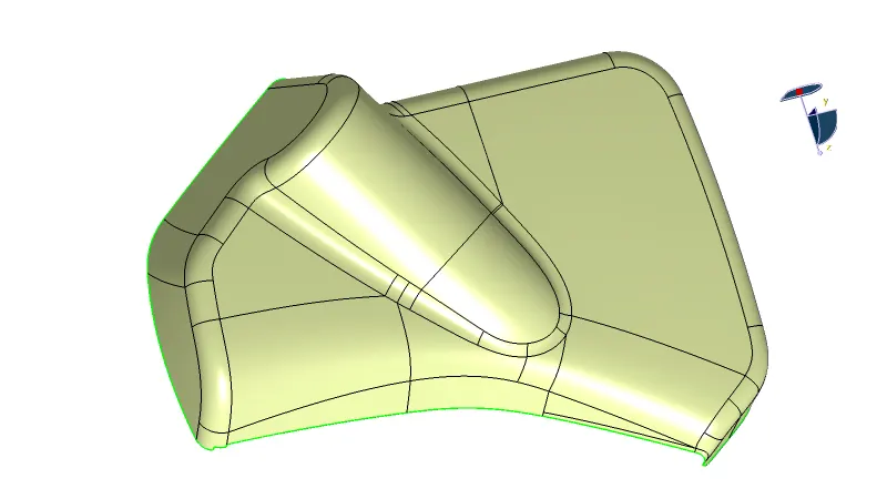
- CLASS B surface having all Engineering features likes ribs, Screw Bosses & Dog House.
- For this we need Class A surface and need to Offset that so create a new geometrical set and offset it as per given Thickness 2.5 mm inside.
- After Offsetting some patch in it, so extract the side boundaries then make that as a smooth curve.
- Then do sweep with reference surface.
- After the patchy surface rework, check the boundaries on green which is in smooth finish not having any errors in the surface.
- Take Overall Boundary of Class B surface and extrapolate it 3 to 5 mm as per our convenience.
- Go to extrapolate tool in Operations tool bar, select the boundary and put in curvature continuity.
- Now we created the CLASS B Surface.
CLASS C:
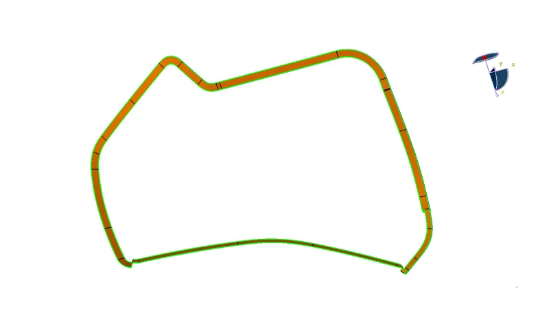
- CLASS C surface provides the connectivity as already thickness we provided on class B surface with Class A surface.
- Create a New geometrical set as CLASS C.
- If our class C surface want Parallel means use the draft direction angle method.
- If our Class C surface want in perpendicular means use the reference surface method.
- We need to do create class C surface for two sides so using draft direction in sweep.
- Select the boundaries of two sides and select sweep option then select draft direction option.
- Select the curve and guiding tooling axis and give the value how much depth we want that curve for intersect our class B Surface.
- For perpendicular creation, so we used reference method. Take another two sides boundaries & make a sweep as per our required depth.
- Then join those sweeps and extrapolate in it edges wherever needed.
- Do the trimming operations to get full body as a CLASS C surface in single surface.
CLASS A & C:
- Now we have separate CLASS A & CLASS C surfaces. Create new Geometrical set.
- So now we can join those class A and class c surface by using join command and give 0.001mm, which is the maximum deviation value we can provide to surfaces.
- We have joined those surfaces now next will be trimming operation
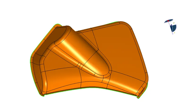
PLASTIC PART /FINAL PART:
- Now trim our class A & C with class B surface to get the desired part. Create new Geometrical set.
- Then define the part body and go to part design workbench, where select the close surface.
- Select our final part, now thick part body gets created.
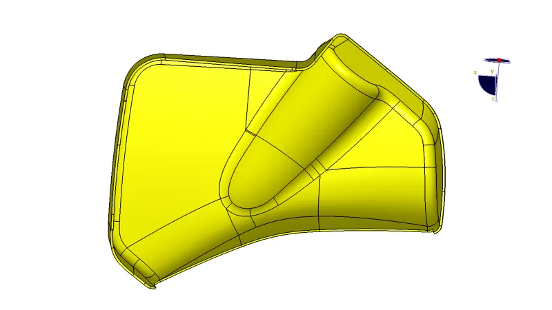
Engineering Features:.
- Now we have the solid body, now we want to create some engineering features, they are listed as follows,
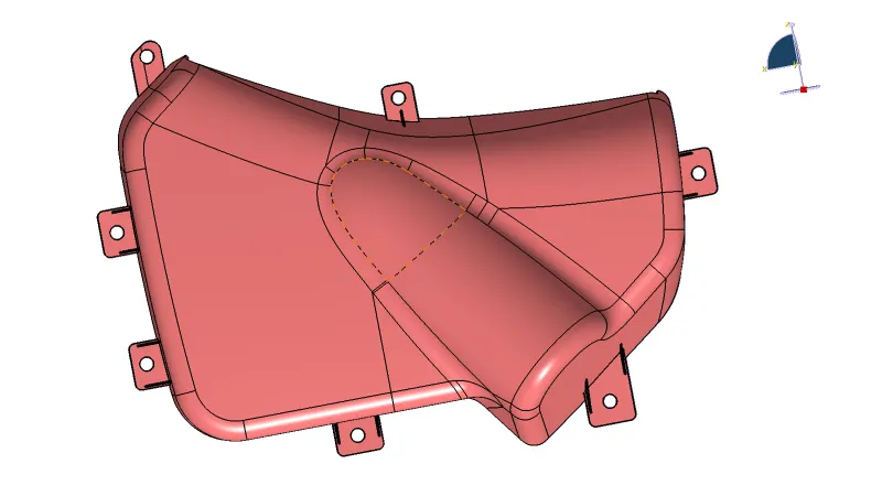
Flanges:
- In this part master section is not provided, so we can create flanges wherever required by considering engineering aspects.
- So, the side wall surface is extracted and point is created in its middle.
- Plane is defined at that point and sketching is done; line is created.
- Then it is extruded,25 mm outside, then new part body is defined and thick surface tool is used.
- Here we created line which is perpendicular to our sketcher line. Offset it 15 mm on both sides.
- Split it with our offset surface, draft is provided of 1.5 degree towards our tooling axis
- Stiffener is provided for giving enough strength to the flange we created.
- The same process is followed in Six places for flanges creation separately.
- Then assemble it to one part and union trim was done.
Flange Holes:
- Extract the flange surface and make a point in its middle surface.
- From Lower Substrate Heat stakes take that hole as reference and make a sketch of hole in flange of 8.5 mm circle then constrain it as concentricity.
- Pocket that hole and remove it from our main Part Body by using Boolean operations.
- Same process is followed for other flanges also.
- Then do draft as well of 1.5 degree with the main tooling axis.
- Now we were provided fillets as well.
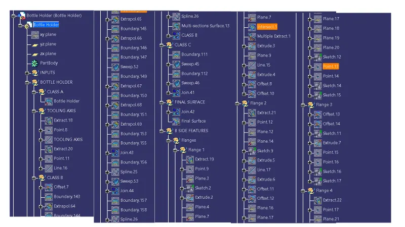
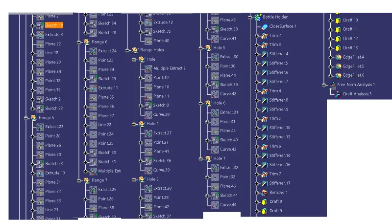
Tree Structure:
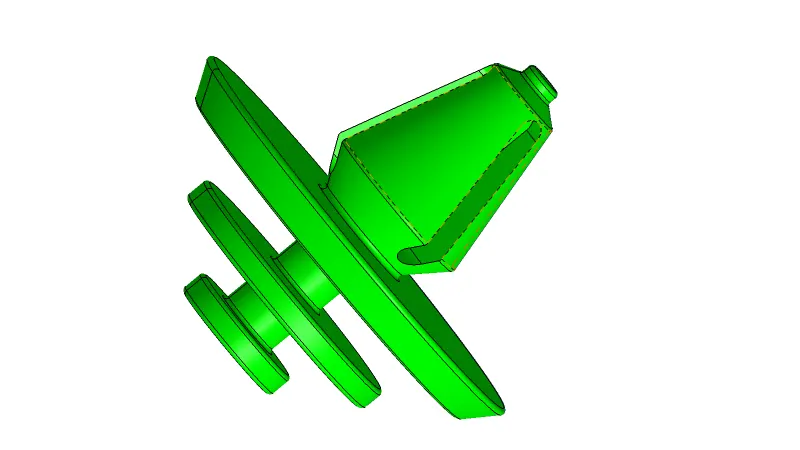
Push Pin:
- These pins are used for the assembly purpose.
- These pins are guided into the sheet metal body.
- The pin is assembled over the dog house on one side and other into sheet metal.
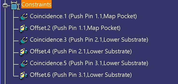
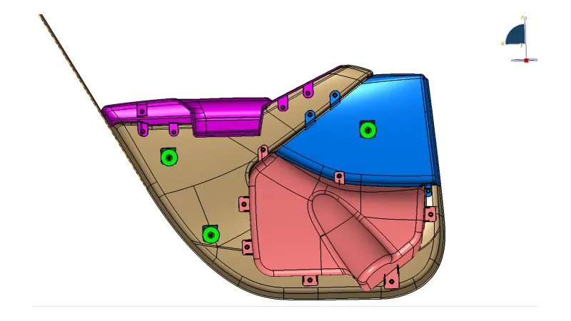
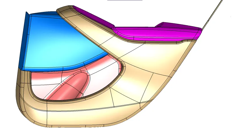
FINAL ASSEMBLY
- The components that are created in separate part files and then inserted into assembly files they are assembled at their working position by applying constraints to them.
- To create an assembly using this approach, it is recommended to insert the first components and fix their position after properly orienting them in the 3D space the components can be inserted and positioned with reference to the first components.
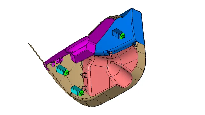
Points observed:
- Arm rest class A surface is not proper there is a discontinuity at an edge. Hence it is modified. Arm rest does not clear the draft analysis with the single tooling axis.
- A side core tooling axis should also be created for clearing the surface and flanges.
- Dog houses are oriented improperly because of uneven surface.
- Side flanges of the bottle holder has 0 deg draft hence not clearing the draft analysis.
- Orientation of bottle holder is not proper it bulges out of class a surface of lower substrate.
- Master section at some places has violated the design rules of the B-side features.
Conclusion:
- We give Draft analysis for A, B & C surface of 3 degree.
- Then for 0.5-degree draft given to the flanges, Screw Bosses & Dog House Inside wall as well.
- 1.5 Degrees of draft is given to outside walls of Dog House.