Week 14 challenge
Aim:
Need to Assemble the Butterfly valve and also need to apply GD&T to the butterfly Valve assembly Drawing.
Design Construction:
- As per the Given 2D drawings ,butterfly valve parts are designed accordingly.
- Drafting is an 2D representation of our designed Part like giving proper dimensions and providing datums to arrest the six degrees of Freedoms.
- Datums are the parameters for arresting the degrees of freedom of the part by using 3-2-1 Principle.
- Datum targets are the parameters that is specifically applied to the specific areas, point & etc..
- Datum and GD&T is approached in each individual Parts.
- Based on the required mode of operation of the parts ,as per its degrees of freedom are arrested.
- Tolerances are provided to each and every required places.
Butterfly Valve Main Body:
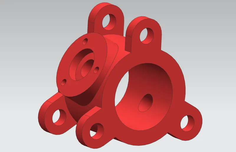
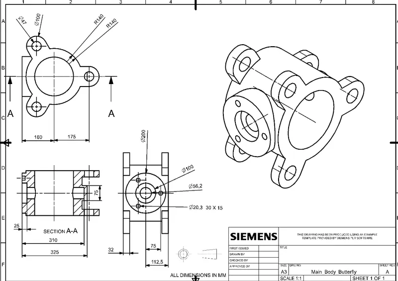
- Created new model , created a body circle of R 140 and D 194. Extrude commend is used to pad the profile.
- Created a ear sketch , dimensions are given below ,Extrude and move object command is used.
- Created new sketch for hole Body profile and Circle was drawn and hole was extruded and substracted from the body.
- Bottom side , cap profile is created and extruded and united to our main body.
- Finally all parts are joined by using Unite Command.
Stem Shaft:
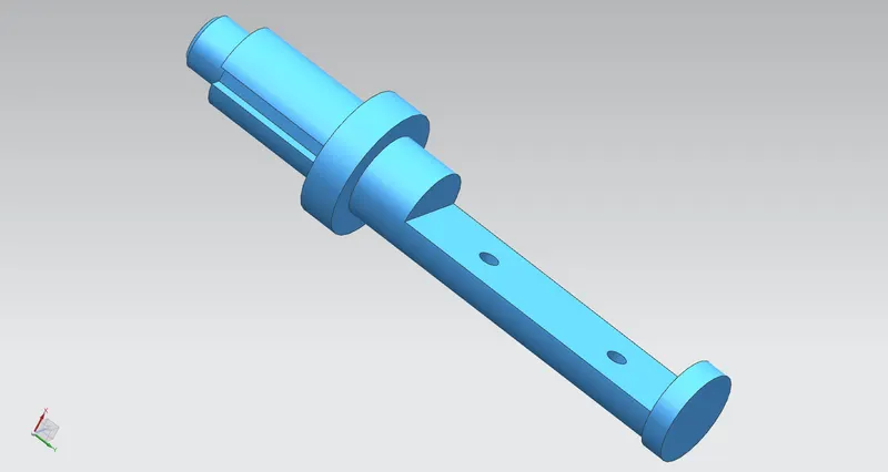
- It is the major part in butterfly valve .
- Created the Sketch with given dimension, profile is created with respect to the center axis revolve command is used.
- Now we got a profile to closed surface with the closing angle of 360 deg.
- Then for Big slot creation, rectangular profile is created with the basic dimensions.
- Then the profile is extruded and it was subtracted from our main body.
- After that 2 hole profiles are created , and extruded as subtracted as well.
- Next slot profile was created and, extruded as subracted as well.
- Chamfering is made as per the given dimension.
Datums:
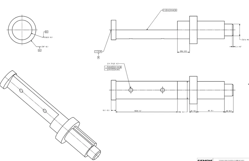
Datum A1-A2
- In our part the below mentioned parts are going to be in conntact with the butterfly body surface.
- So we given A1 and A2 are the primary datums for this shaft.
- It arrest the parts degrees of freedom ( 2 Translation and 2 rotation)
DATUM B:
- In our Part Datum B is provided in bottom surface of the shaft which will mate with the butterfly body.
- It is arresting (1 translation), so one rotation is granted in our shaft ,because the shaft is going to rotate inside the butterfly part.
Retainer:
Constructional Report:
- Retainer is one of the major part in Butterfly Valve.
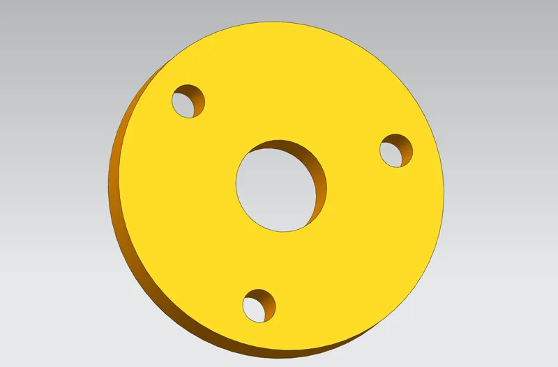
- As per the given dimensions, Circular profile and holes are created.
- Extrude tool is used for providing thickness.
Draftings:
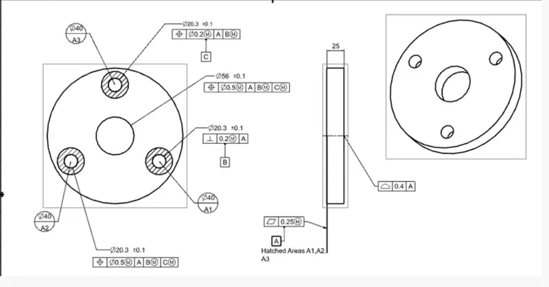
- Using drafting tool we plotted different views and respective dimensions are provided.
Datums:
- In our Part Three datum target areas A1,A2&A3 are used because ,only that much areas are enough, If we go to entire part the production cost would be high.Where (One translation & Two Rotations are arrested)
- One of holes was taken as Datum B.So here (remaining Two Translations are arrested).
- Another hole was taken as Datum C.So here (Remaing One rotation was now arrested).
- Now all degrees of freedom in our part is arrested as shown below.
Disc Plate:
Design Construction:
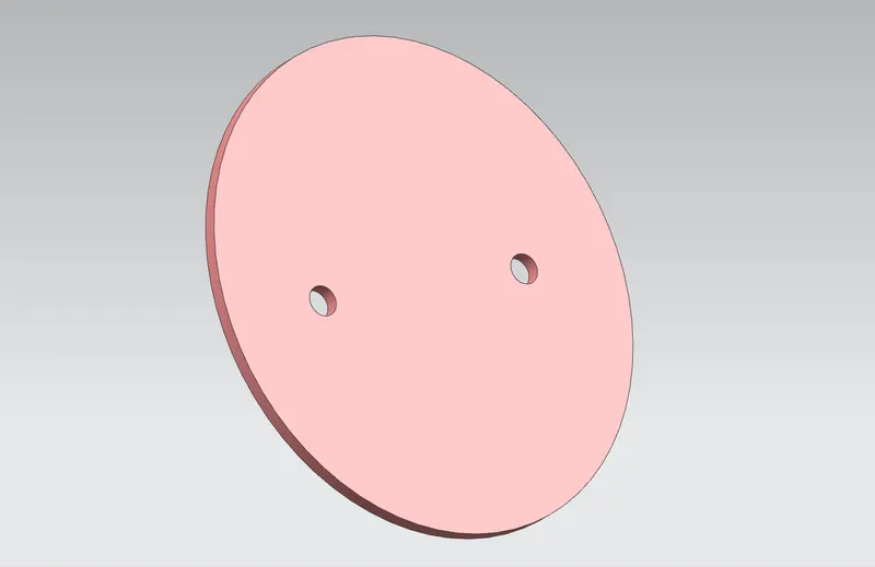
- As per the given 2D drawing ,we created a profile of ellipse.
- Two holes are created in the same Sketch.
- Extrude tool is used for providing thickness of 6mm.
Drafting:
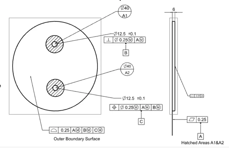
- Base View and Projected views are plotted and dimensions are plotted.
Datums:
- The mating surface is considered as Datum Surface, where the two hatched holes of 20mm radii are considered as datum targets A1 & A2. It will arrest( 1 translation & 2 Rotation)
- One of Hole was considered as Datum B were ( 2 Translation) arrested.
- Anoher hole was considered as Datum C were ( 1 Rotation ) arrested.
- As per the 3-2-1 Principle all degrees of freedom was arrested.
Lever Handle:
Design Construction:
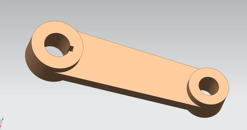
- As per the given 2D drawing , Two Big& Smaller circular profiles are created.
- Then line is created at the both sides of those circles which will be in tangent.
- Provided proper dimensions and make the skech profile as fully Constraint.
- Came out from the sketch and extrude command is used as in single curve only by one.
- Then Unite Command is used for joining three parts into a single Part.
Drafting:
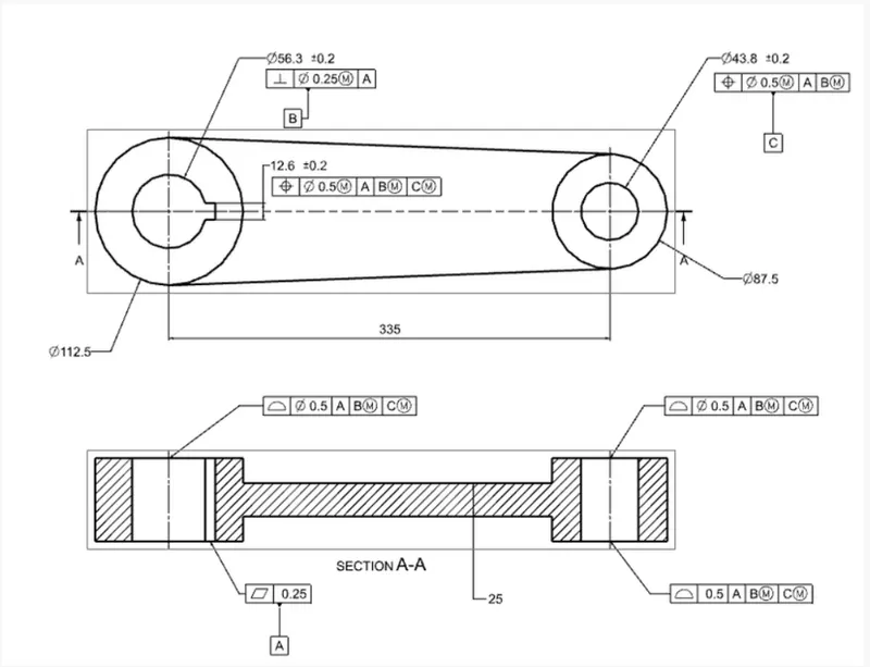
- In our Part Bottom portion of our Big circle is considered as Datum A and flat profile geometric tolerance is provided.
- So 1 Translation and 2 Rotations were arrested.
- Top Circle is considered as datum B, so 2 translation was arrested.
- Then smaller circle on another side is considered as Datum C, Here 1 rotation was arrested.
Nut:
Design Construction:
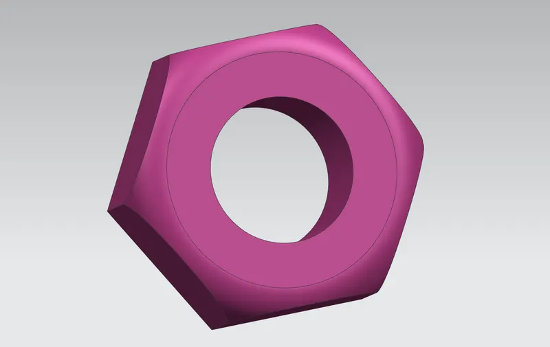
- As per the Design Standards,in the sketch line is created by using pattern curve of considering sides per total degree.
- Inside Circle is created and extrude command is used to provide thickness.
- Change the sketch plane provide the fillet profile and used revolve command.
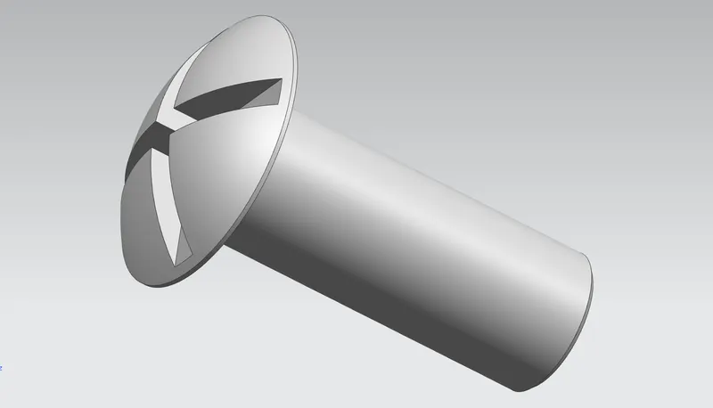
- The fillets are provided on each edges of the nut as shown inn fifure below.
Drafting:
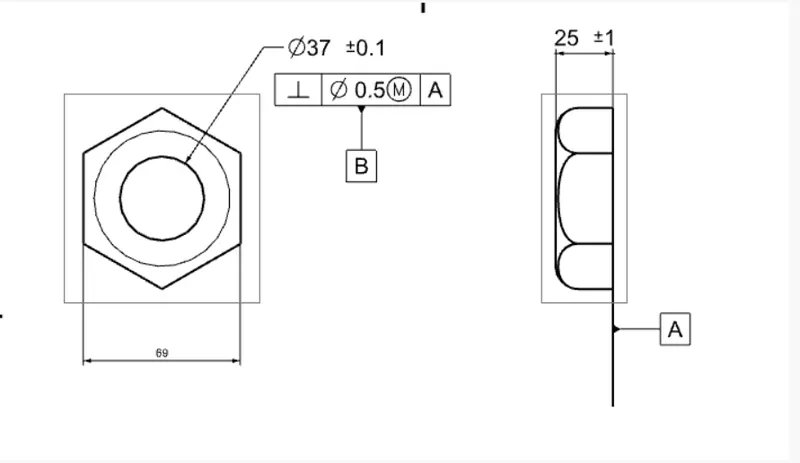
- In our part bottom surface is considered as Datum A.Here (2 Rotations and 1 translations)
- Hole profile is considered as Datum B were 2 translations are arrested.
- In our part we allowed to rotate i.e one degree of freedom is not arrested ,beacuse it is a nut it should rotate.
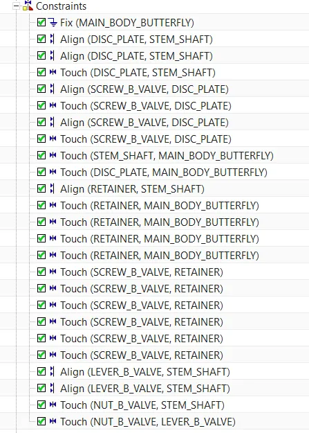
Geometrical Constraints:
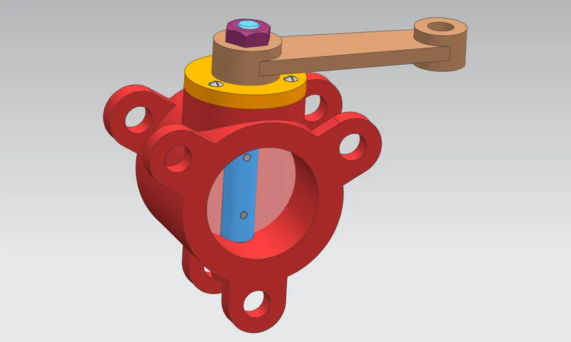
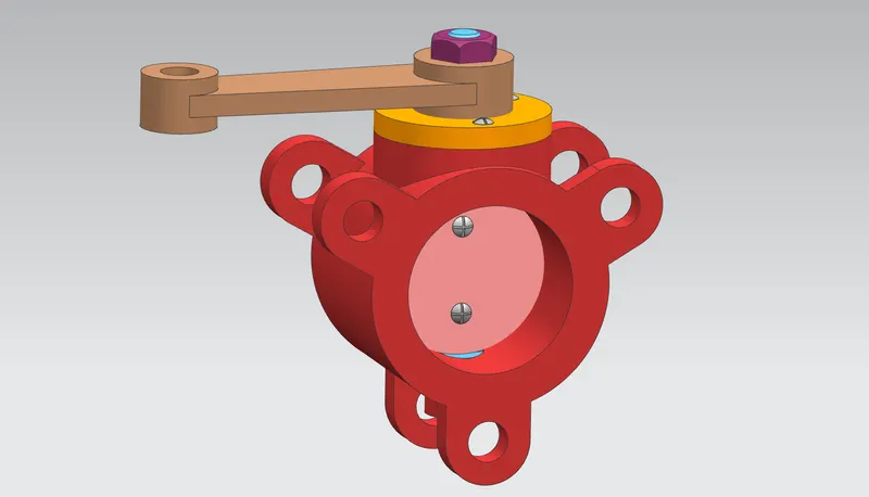
Assembled Parts:
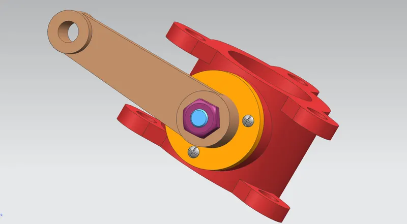
Conclusion:
Butterfly Valve assembly is created and GD&T concepts are provided as per the Standards.