Week 11 - Project - A pillar Design with Master Section
Aim:
Creation of the Screw boss for A Pillar by using Master Sections of considering the design rules.
Constructional Report:
Tooling Axis:
- The direction in which the Mold or core and cavity opens is the tooling axis.
- For Tooling Axis Creation, here we used the bisecting method.
- We have used the lines which are extracted from the master section and then isolated them as well then define that.
- Create a point in between the first two lines, then create a bisecting line with respect to the point.
- Do the same process with another two lines and create the main tooling axis.
- Put the Class A surface in No material Mode in View tool bar.
- Go to Insert - > Analysis - > Feature Draft Analysis.
- Click the Compass, drag the compass towards that line and place vertically along it and click lock button.
- Select on any part of the surface then see some colour changes on it.
- Select 3 degrees as green and check the surface it shows all as green, it means our created tooling axis is correct.
CLASS B:
- Create new Geometrical set as Class B
- CLASS B surface having all Engineering features likes ribs, Screw Bosses & Dog House.
- For this we need Class A surface and need to Offset that so create a new geometrical set and offset it as per given Thickness 2.5 mm.
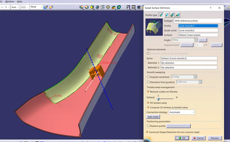
- After Offsetting some patch in it, so extract the side boundaries then make that as a smooth curve.
- Then do sweep with reference surface.
- After the patchy surface rework, check the boundaries on green not having any errors in the surface.
- Take Overall Boundary of Class B surface and extrapolate it 3 mm.
- Go to extrapolate tool in Operations tool bar, select the boundary and put in curvature continuity.
- Now we created the CLASS B Surface.
CLASS C:
- CLASS C surface provides the connectivity as already thickness we provided on class B surface with Class A surface.
- Create a New geometrical set as CLASS C.
- If our class C surface want Parallel means use the draft direction angle method.
- If our Class C surface want in perpendicular means use the reference surface method.
- We need to do create class C surface for two sides so using draft direction in sweep.
- Select the boundaries of two sides and select sweep option then select draft direction option.
- Select the curve and guiding tooling axis and give the value how much depth we want that curve for intersect our class B Surface.
- For perpendicular creation, so we used reference method. Take another two sides boundaries & make a sweep as per our required depth.
- Then join those sweeps and extrapolate in it edges wherever needed.
- Do the trimming operations to get full body as a CLASS C surface in single surface.
CLASS A & C:
- Now we have separate CLASS A & CLASS C surfaces. Create new Geometrical set.
- So now we can join those class A and class c surface by using join command and give 0.001mm, which is the maximum deviation value we can provide to surfaces.
- We have joined those surfaces now next will be trimming operation
PLASTIC PART /FINAL PART:
- Now trim our class A & C with class B surface to get the desired part. Create new Geometrical set.
- Then define the part body and go to part design workbench, where select the close surface.
- Select our final part, now thick part body gets created.
DOG HOUSE:
- Dog house is secondary Class B side Engineering feature.
- Using for engagements one part with another part and also having some engineering features.
- Here we used Master sections, which having a predefined intersection. From master section 2, we have created 3 points along the intersections.
- Then we isolated that, after defined it to coordinates.
- By using those three points we have created plane for sketching.
- Then do positioning sketch and project the master section and make as reference elements and do the sketch over and make as iso constraints then we did pad to the required length. (Measure the length between by using the measure tools).
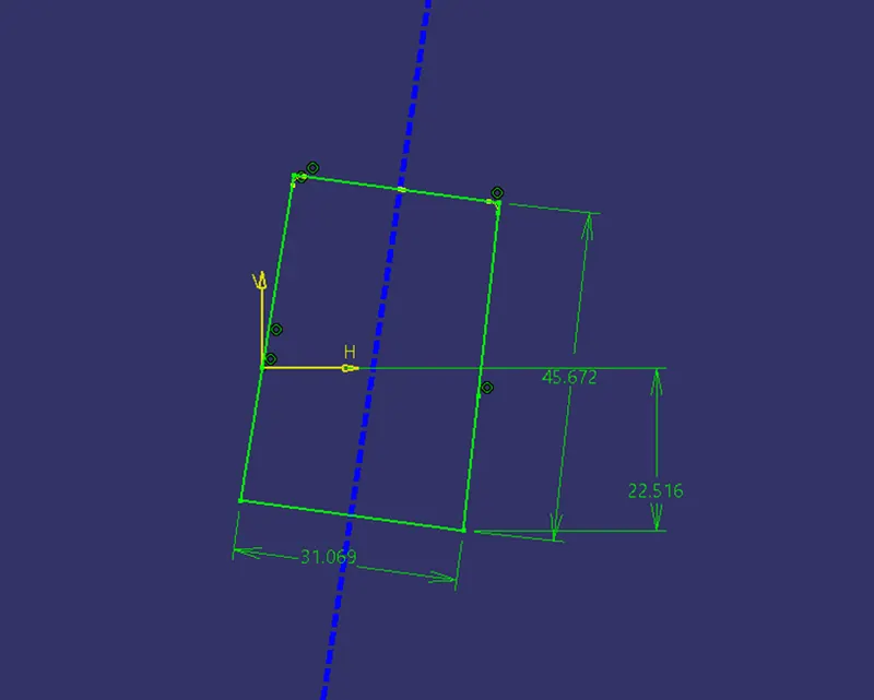
- After pad we did draft behind faces of padded body of 1.5 degree. Then do shell of 2.5 mm, on front face of the part.
- Then creates the line through the point which we used for creating the plane.
- Extrude it, for cutting the base and offset it for 5mm to top. The height should be 3 to 6mm
- Then we did multiple extraction from outside faces of shell body and offset to 1mm inside. That is for bottom thickness of our dog house, it should 40 % of its part thickness so (5 X 40% = 1mm).
- Then trim it with the line we did extrude before. Then split it with our shell body to get desired dog house.
- Then do draft inside 0.5 degree to left right and top portions.
- Do fillets outside 3mm and inside 0.5 mm inside of top portion and (2.5 mm thickness, outside fillet 3mm so (3 – 2.5 = 0.5 mm), (1mm thickness, outside fillet 3mm so (3 – 1 = 2mm).
- Now our Dog House is created.
RIBS:
- Ribs are Engineering features which gives additional strength to the adjacent body of the part.
- We have used the plane which we defined before the do sketching, projected the master section and we make that as reference elements, then did the sketch over that and makes that into iso constraints.
- Then Pad it, it is ok if the pad goes outside as well, later insert a body and do union trim with our dog house.
- Then we did the draft of 0.5 deg to the all faces with support element as behind face of dog house.
- Filleting is done to the edges of 0.2 mm, then our ribs are gets created inside as well in dog house body.
Lifter Axis:
- Lifter axis is similar to the tooling axis, but it is used for lifting or clearing the core and cavity to different direction from main tooling axis.
- Already we have the plane and point, that is the lifter axis so create the line and extend as per our requirement.
- Then do draft analysis with that axis and put 0.5 degree, all faces are showing in green then its ok.
Key Hole:
- It is an additional profile we want to create it over the dog house.
- So, extract the two lines over the dog house then create the plane.
- Then do sketching as per the manual, then insert a body do remove from our dog house.
- Then finally did union trim with main part body for removing unwanted bottom portion behind the part body of do house.
- Provided draft of 1.5 degree to the inside circle and 0.5 degree to the inside open faces.
- We did minimum fillet of 0.2 mm to the dog house with part body.
- Now all work is completed.
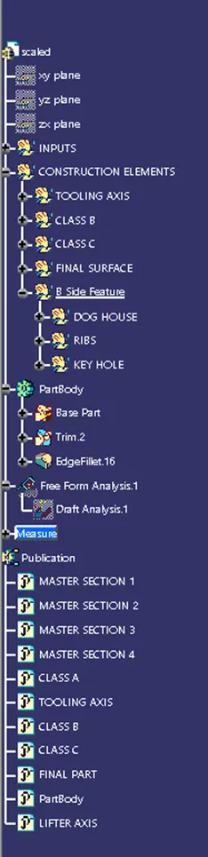
Tree Structure:
Conclusion:
- We given Draft analysis for A, B & C surface of 3 degree.
- Then for dog house outside 1.5 degree & inside 0.5 degree.
- Draft analysis Report is attached with this, kindly find that.