Simulation of a flow over the backward-facing step in OpenFOAM
Aim: Simulation of a flow over the backward-facing step in OpenFOAM
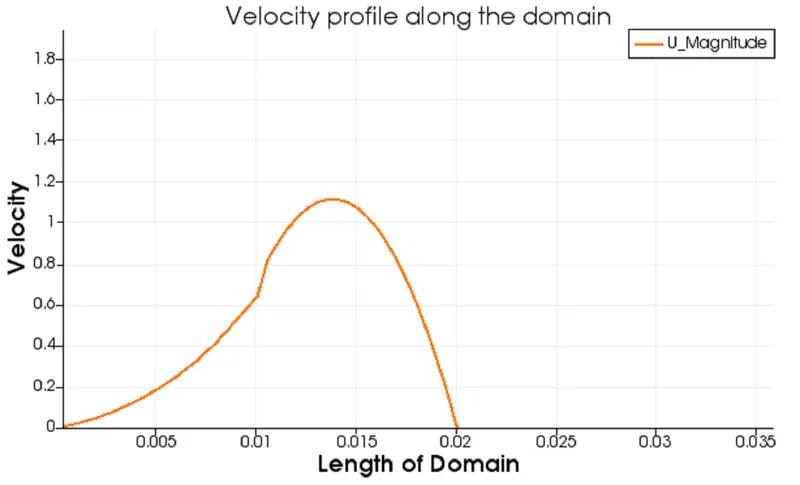
Abstract: Backward facing step (known as BFS) is widely known for its application on turbulence in internal flows. The flow separation is caused due to the sudden changes in geometry which will be evident as the blockmesh file creates the geometry. This causes a zone of recirculation and a point of flow reattachment. The present numerical study describes the variation of velocity at a distance of 0.085 m from the inlet.
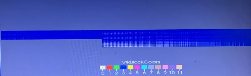
The behavior of the velocity graph is observed while changing the mesh from 20 to 200 (along the x-axis), from 10 to 20 (along with the y axis), and grading factor from 1 to 0.2 (along the x and y-axis).
Coding procedure in OpenFoam
- The flow in the given profile is incompressible (density of the fluid is not changing wrt to time)
- The cavity folder is copied from the incompressible folder to the run folder by typing cp -r cavity/$ FOAM_RUN.
- The tutorial files should not be altered as such a command terminal will give an error on execution consequently, it will be time-consuming to download the OpenFoam again.
- The 0 folder, inside the cavity folder, contains pressure and velocity profiles at the initial and boundary condition.
- The system folder, inside the cavity folder, contains blockMeshDict, controlDict, fvschemes, fvsolution.
- The blockMeshDict file is used for creating the geometry of the profile.
- The profile under consideration has a front view only, it will be better to create an isometric view of the profile to have a better understanding of the blockMeshDict file.
Geometry creation
The profile under consideration has been converted into five blocks as shown in figure

The vertices have been indexed from the backside of the block to the front side. Since OpenFoam uses C++ so indexing starts from zero.
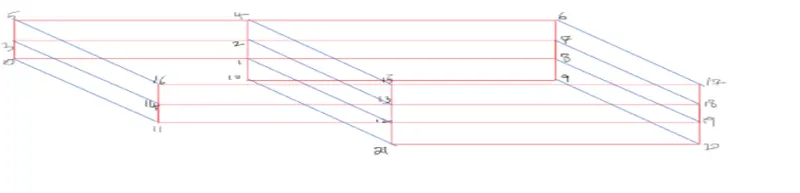
As per the given figure, there are a total of 21 vertices. The zero vertice has a coordinate of (0, 0, 0), the total length of the domain is 0.20 meter (along X-axis), the length along(y-axis) is 0.01 meter.
Accordingly, coordinate points of all the 21 vertices have been listed in the blockMesh file.
Block generation
For defining the blocks we need to define the right order of vertices.
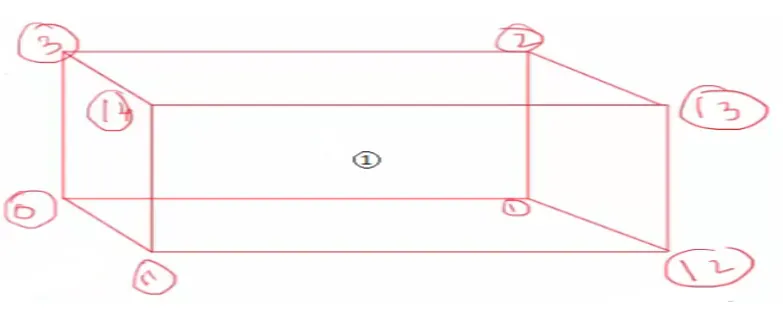
Let us take block number 1, it will be hex(0 1 2 3 11 12 13 14) (20 10 1) simplegrading(1 1 1). The orientation of the vertices is complying with the flow direction. If we would have taken in opposite order the result will be different. The second bracket defines the number of grid points along the x,y, z-axis. The third bracket defines the technique known as mesh stretching.
Accordingly, the rest of the blocks are created in the same way.
Grading factor = (Size of end cell)/(Size of starting cell)
If the grading factor is 0.2 which means the size of the end cell is smaller than the size of starting cell.
If the grading factor is 10 which means the size of the end cell is greater than the size of starting cell.
If the grading factor is 1 which means the size of the end cell is equal to the size of starting cell.
Thus, the grading factor gives the finer mesh at the boundary to get proper flow conditions.
Boundary condition
There are four boundary condition in the given profile viz:
- Inlet wall (type patch)
- Outlet wall (type patch)
- Front and back ( type empty)
- No-slip walls (type no-slip)
Accordingly, faces that contribute to each boundary condition are listed in the blockMeshDict file.
The pressure and velocity profile listed inside the 0 folder is changed as per the given profile.
The value of timesteps should be taken very small owing to the CFL number. As such large time steps value will result in making up the profile unstable.
- After making all these changes in the four files blockMesh is executed in the command terminal for the cavity folder.
- The checkMesh command is executed to check whether the mesh is stable or not.
- The icoFoam is executed in the command terminal to calculate the value of the velocity for the inner nodes.
- Once the simulation is completed paraFoam is executed to see the geometry profile.
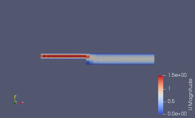
- Plot over line is executed to observe the variation of velocity along the length of the domain.
- Blockmesh file for creating the geometry of a profile in OpenFoam.
Case-1 :
- The grid points along with the x-axis = 20
- The grid points along with the y axis = 20
- Uniform mesh size simple grading (1 1 1)
/*--------------------------------*- C++ -*----------------------------------*
  =========                 |
        /  F ield         | OpenFOAM: The Open Source CFD Toolbox
       /   O peration     | Website:  https://openfoam.org
      /    A nd           | Version:  8
     /     M anipulation  |
*---------------------------------------------------------------------------*/
FoamFile
{
    version     2.0;
    format      ascii;
    class       dictionary;
    object      blockMeshDict;
}
// * * * * * * * * * * * * * * * * * * * * * * * * * * * * * * * * * * * * * //

convertToMeters 0.01;

vertices
(
    (0 0 0) // 0
    (8 0 0) // 1
    (8 0.5 0) // 2
    (0 0.5 0) //3
    (8 1 0) // 4
    (0 1 0) // 5
    (20 1 0) // 6
    (20 0.5 0) //7
    (20 0 0 ) //8
    (20 -1 0) //9
    (8 -1 0) //10
    (0 0 0.1) //11
    (8 0 0.1) //12
    (8 0.5 0.1)//13
    (0 0.5 0.1) //14
    (8 1 0.1) //15
    (0 1 0.1) //16
    (20 1 0.1) //17
    (20 0.5 0.1) //18
    (20 0 0.1) //19
    (20 -1 0.1) //20
    (8 -1 0.1) //21
);

blocks
(
    hex (0 1 2 3 11 12 13 14) (20 10 1) simpleGrading (1 1 1)
    hex (3 2 4 5 14 13 15 16) (20 10 1) simpleGrading (1 1 1)
    hex (2 7 6 4 13 18 17 15) (20 10 1) simpleGrading (1 1 1)
    hex (1 8 7 2 12 19 18 13) (20 10 1) simpleGrading (1 1 1)
    hex (10 9 8 1 21 20 19 12) (20 10 1) simpleGrading (1 1 1)
);

edges
(
);

boundary
(
    inletWall
    {
        type patch;
        faces
        (
            (0 11 14 3) // anticlockwise
            (3 14 16 5) // anticlockwise
        );
    }
    outletwall
    {
        type patch;
        faces
        (
             (9 8 19 20) // clockwise
             (8 7 18 19) // clockwise
             (7 6 17 18) // clockwise
        );
    }


    frontAndBack
    {
        type empty;
        faces
        (
            (0 3 2 1) // back clockwise
            (3 5 4 2) // back clockwise
            (10 1 8 9) // back clockwise
            (1 2 7 8) // back clockwise
            (2 4 6 7) // back clockwise
            (14 11 12 13)// front anticlockwise
            (16 14 13 15)// front anticlockwise
            (12 21 20 19)// front anticlockwise
            (13 12 19 18)// front anticlockwise
            (15 13 18 17)// front anticlockwise
        );
    }

    Noslipwalls
    {
        type wall;
        faces
        (
             (6 4 15 17) // top anticlockwise
             (4 5 16 15) // top anticlockwise
             (10 9 20 21) // bottom clockwise
             (11 0 1 12) // bottom clockwise
             (1 10 21 12) // stepsidewall anticlockwise

         );
     }
);

mergePatchPairs
(
);

// ************************************************************************* //
- ControlDict file for creating a time marching solution
FoamFile
{
    version     2.0;
    format      ascii;
    class       dictionary;
    location    "system";
    object      controlDict;
}
// * * * * * * * * * * * * * * * * * * * * * * * * * * * * * * * * * * * * * //

application     icoFoam;

startFrom       startTime;

startTime       0;

stopAt          endTime;

endTime         0.5;

deltaT          0.00001;

writeControl    timeStep;

writeInterval   20;

purgeWrite      0;

writeFormat     ascii;

writePrecision  6;

writeCompression off;

timeFormat      general;

timePrecision   6;

runTimeModifiable true;


// ************************************************************************* //

/*--------------------------------*- C++ -*----------------------------------*
  =========                 |
        /  F ield         | OpenFOAM: The Open Source CFD Toolbox
       /   O peration     | Website:  https://openfoam.org
      /    A nd           | Version:  8
     /     M anipulation  |
*---------------------------------------------------------------------------*/- Defining pressure at the walls of the profile.
/*--------------------------------*- C++ -*----------------------------------*
  =========                 |
        /  F ield         | OpenFOAM: The Open Source CFD Toolbox
       /   O peration     | Website:  https://openfoam.org
      /    A nd           | Version:  8
     /     M anipulation  |
*---------------------------------------------------------------------------*/
pressure profile

FoamFile
{
    version     2.0;
    format      ascii;
    class       volScalarField;
    object      p;
}
// * * * * * * * * * * * * * * * * * * * * * * * * * * * * * * * * * * * * * //

dimensions      [0 2 -2 0 0 0 0];

internalField   uniform 0;

boundaryField
{
    inletWall
    {
        type            zeroGradient;
    }

    outletwall
    {
        type            fixedValue;
        value           uniform 0;
    }

    Noslipwalls
    {
        type             zeroGradient;
    }

    frontAndBack
    {
        type            empty;
    }
}

// ************************************************************************* //- Defining velocity at the walls of the profile.
/*--------------------------------*- C++ -*----------------------------------*
  =========                 |
        /  F ield         | OpenFOAM: The Open Source CFD Toolbox
       /   O peration     | Website:  https://openfoam.org
      /    A nd           | Version:  8
     /     M anipulation  |
*---------------------------------------------------------------------------*/
FoamFile
{
    version     2.0;
    format      ascii;
    class       volVectorField;
    object      U;
}
// * * * * * * * * * * * * * * * * * * * * * * * * * * * * * * * * * * * * * //

dimensions      [0 1 -1 0 0 0 0];

internalField   uniform (0 0 0);

boundaryField
{
    inletWall
    {
        type            fixedValue;
        value           uniform (1 0 0);
    }

    outletwall
    {
        type            zeroGradient;
    }

    Noslipwalls
    {
        type            noSlip;
    }

    frontAndBack
    {
        type            empty;
    }
}

// ************************************************************************* //- Geometrical representation of the profile (surface with edges).
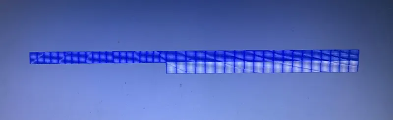
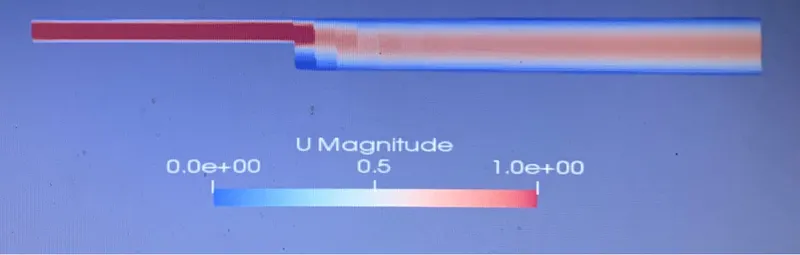
- Variation of velocity along with the given profile
- Velocity graph at the distance of 0.085m
Case-2
- The grid points along with the x-axis = 200
- The grid points along with the y axis = 20
- Uniform mesh size simple grading (0.2 0.2 1)
Please note that in this case only section of the coding is represented here as the other coding algorithm is same.
blocks
(
    hex (0 1 2 3 11 12 13 14) (200 20 1) simpleGrading (0.2 0.2 1)
    hex (3 2 4 5 14 13 15 16) (200 20 1) simpleGrading (0.2 0.2 1)
    hex (2 7 6 4 13 18 17 15) (200 20 1) simpleGrading (0.2 0.2 1)
    hex (1 8 7 2 12 19 18 13) (200 20 1) simpleGrading (0.2 0.2 1)
    hex (10 9 8 1 21 20 19 12) (200 20 1) simpleGrading (0.2 0.2 1)
);- Geometrical representation of the profile (surface with edges).
- Variation of velocity along with the given profile
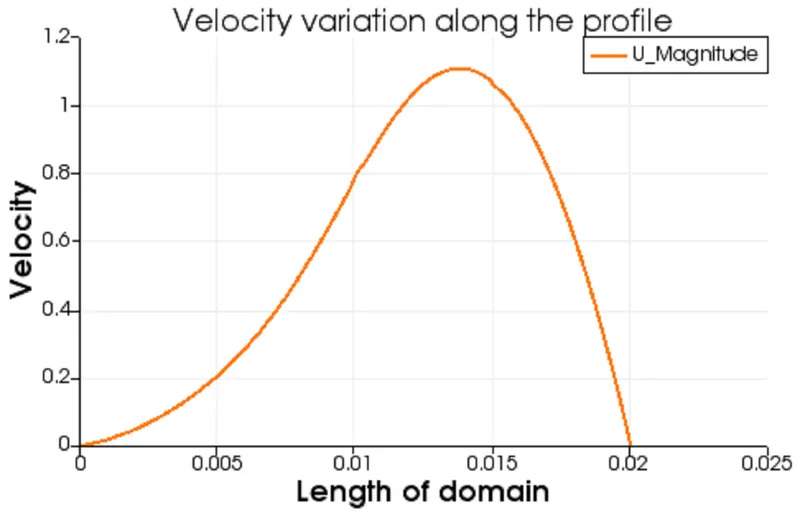
- Velocity graph at the distance of 0.085m
Conclusion
It can be inferred from the velocity profile that a better distribution is obtained for mesh grading factor 0.2.
Also, the CFL number increases as the grading factor decreases.
The grading factor produces the finer mesh at the boundary to capture the flow condition.