Section Modulus calculation and optimization
OBJECTIVE
To understand and find the section modulus of the hood and then do the necessary changes to improve and optimize the section modulus of the hood
INTRODUCTION
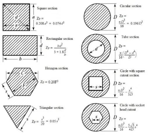
Section modulus is a geometric property for a given cross-section used in the design of beams or flexural members. Other geometric properties used in design include area for tension and shear, radius of gyration for compression, and moment of inertia and polar moment of inertia for stiffness. Any relationship between these properties is highly dependent on the shape. There are two types of section moduli the elastic section modulus and the plastic section modulus. The elastic section modulus is defined as,
S=I/y
S is the Section Modulus
I is the second moment of area (or area moment of inertia, not to be confused with moment of inertia)
y is the distance from the neutral axis to any given fibre. It is often reported using y = c, where c is the distance from the neutral axis to the most extreme fibre.
IMPORTANCE
- It is significant for beam and flexural member design.
- More the section modulus, the more the member is resistant to the bending of the beam.
- It is easier to calculate stresses in the beam and an exact measure of the strength of steel.
- If two beams are made of the same material and comparing the section modulus of two beams, the beam with bigger section modulus will be tougher and more capable to withstand larger loads.
PROCEDURE
1.First create a datum plane which passes through the middle portion of the hood.
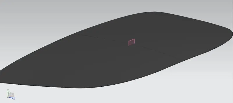
2. Create an intersection Curve with the help of the plane consider both the Outer & Inner panels of the hood. After that create a sketch with respect to the datum plane created and project the curve into the sketch
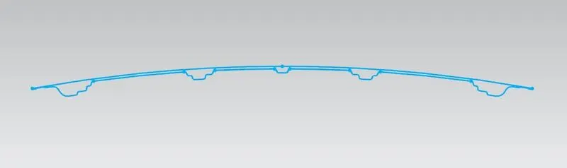
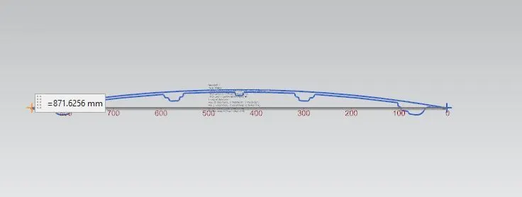
3. Measure the distance of the outer hood inorder to find the value of y in the section modules equation
CASE STUDY
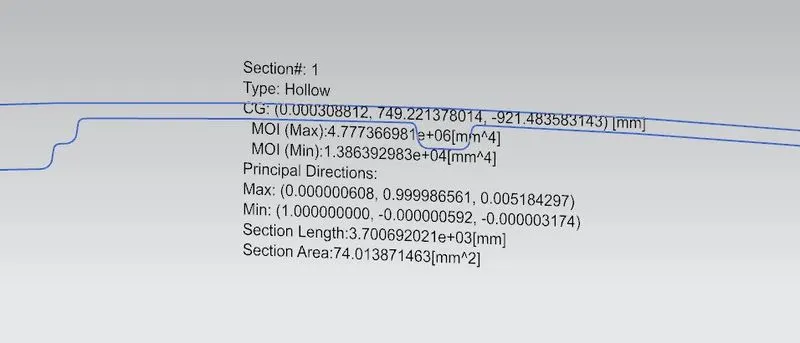
Case-1
In this initial hood design is used
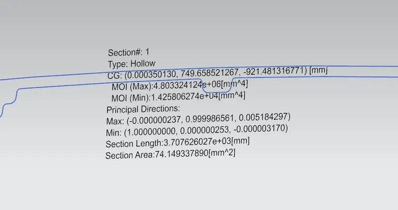
Case-2
In this Outer panel is offseted to 1mm above
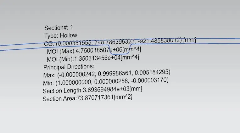
Case-3
In this Outer panel is offseted in opposite direction from the orginal position by 1mm
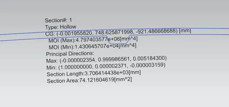
Case-4
In this the the lower side of panel that is the embossed side is offsetted below with a distance of 1mm
CALCULATIONS
- From the above image the Minimum MOI is used for the calcualtion of the section modules, it is because the section modules with respect to the Min MOI will give the weakest section. So the I value will be minimum MOI
- In all the above cases the y value will not change, it is distance from 1 end to neutral axis. In here the distance is 871.62mm, the y value will be 871.625/2 = 435.812mm
- S = Min MOI / y
RESULTS
| Sl.No | Case Study | I (Min MOI)`(mm^4)` | y (mm) | S=I/y `(mm^3)` |
| 1 | Orginal Hood position | `1.386*e^4` | 435.812 | 31.802 |
| 2 | Outer panel is offset above with a distance of 1mm from the orginal position of Outer panel | `1.425*e^4` | 435.812 | 32.697 |
| 3 | Outer Panel is offset below with a distance of 1mm from the orginal position of outer panel | `1.3503*e^4` | 435.812 | 30.983 |
| 4 | Emboss panel is offset below with a distance of 1mm | `1.4306*e^4` | 435.812 | 32.826 |
Larger section modulus be stronger and capable of supporting greater loads. So from the above we can see that 4th case has more section modulus so by increasing area we can get more stronger and capable of supporting greater loads
CONCLUSION
Thus, the section modulus of the Front Hood of a car was calculated and compared with the optimized hood and found the better result. Hence the concluding is that when the sectional area of the hood increases the stiffness and resistance of the hood strength will also be increased. Hood should design in such a way that it should absorb all maximum loads when a crash happens.