Radar Mast & Final Assembly of Yacht
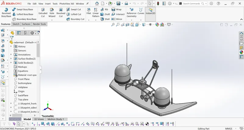
Radar Mast:
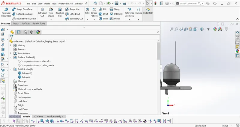
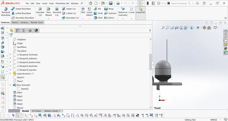
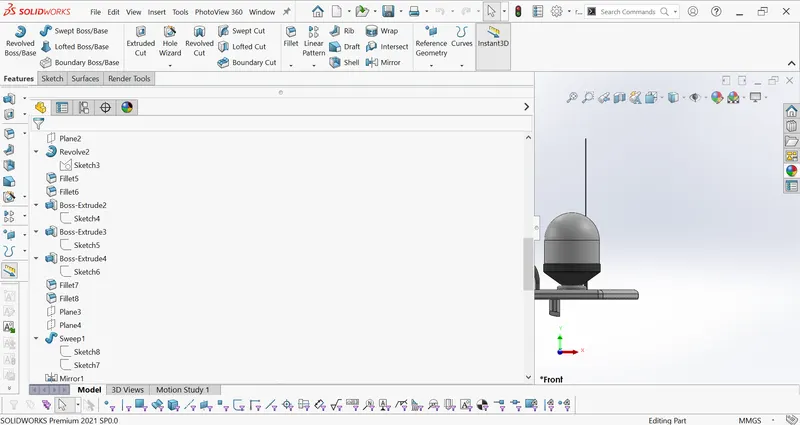
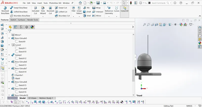
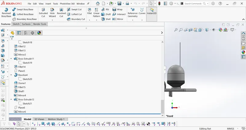
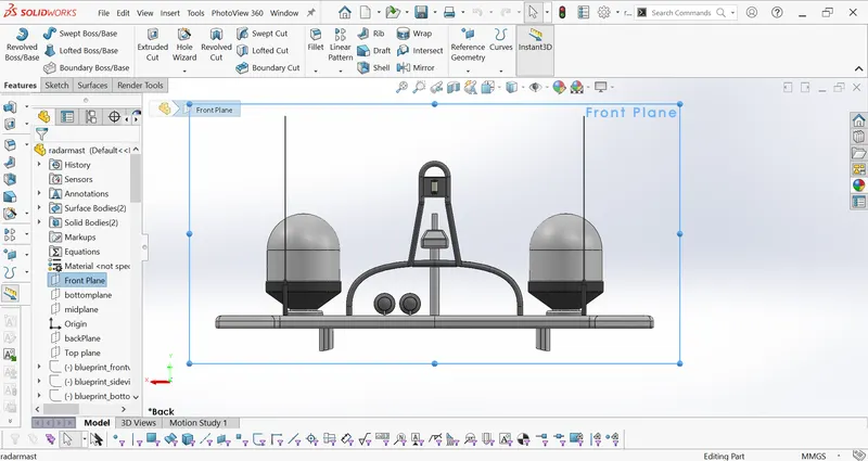
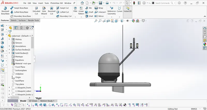
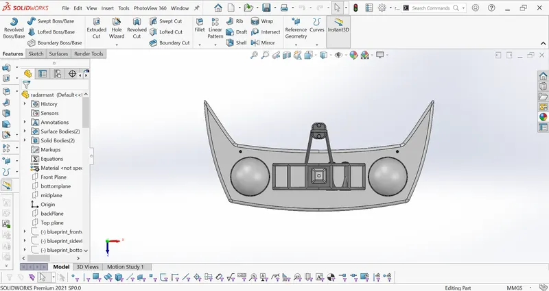
Feature tree and
top,front side and isometric views

TITLE:Design of a YACHT from scratch
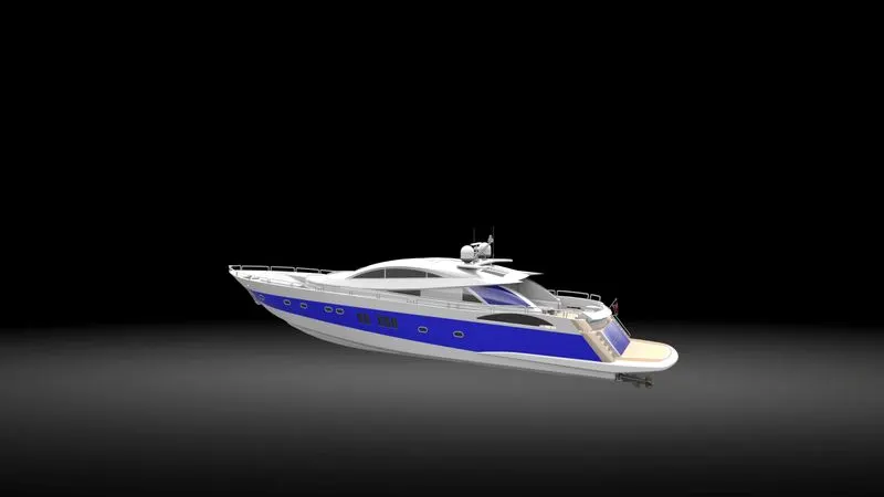
OBJECTIVE:The objective of this project is to learn the solidworks while designing the yacht from scratch.
INTRODUCTION:The yacht is a large and usually expensive boat used for racing or for traveling around.Solidworks is a computer aided Design software where 3D solid modeling,Assembling and Analysing the components can be done easily.
In this yacht design we model all the parts of the yacht except the engine.The parts are modeled individually by using the solidworks features and then they are assembled in solidworks.
To get the realistic view of the yacht we use solid works visualization to look as realistic as possible.
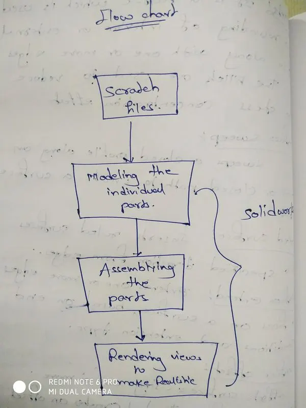
DESIGN METHODOLOGY:Since we are designing this from the scratch files we already know the dimensions of the parts
we use those dimensions to model the parts individually in solidworks by using commands and features
Then we assemble all the parts together to make a complete part
Then we use the solidworks visualization to make the renderring views to make is as realistic as possible.
ACTUAL DESIGN methodology: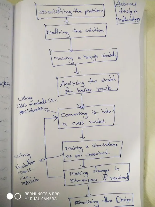
DESCRIPTION:
The components of the yacht are
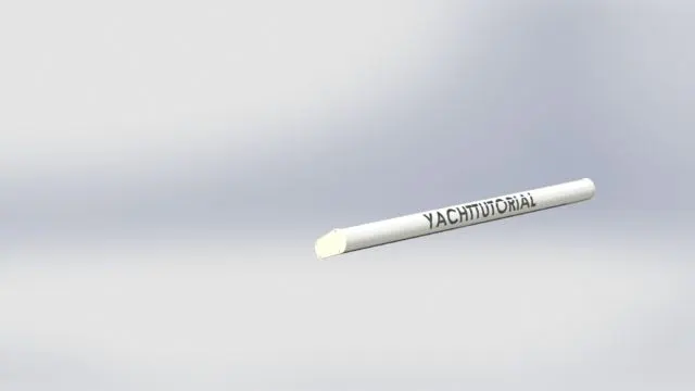
1.Radar
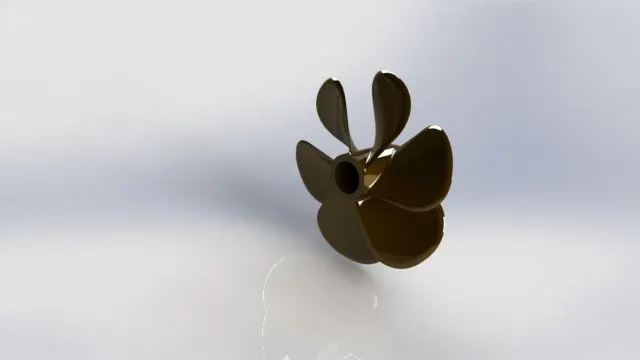
2.propeller
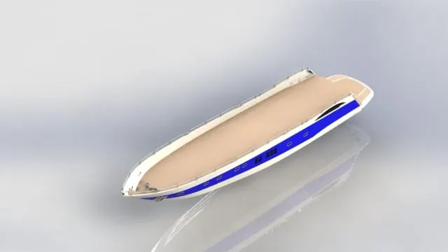
3.hull
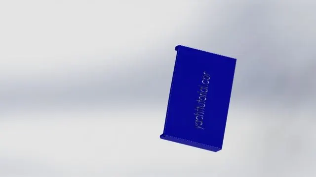
4.garage door
5.front seat
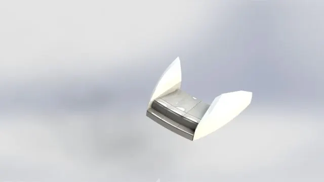
6.middle seat
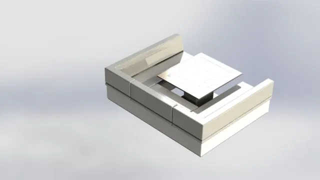
7.rare seat
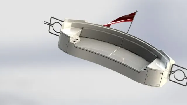
8.super structure
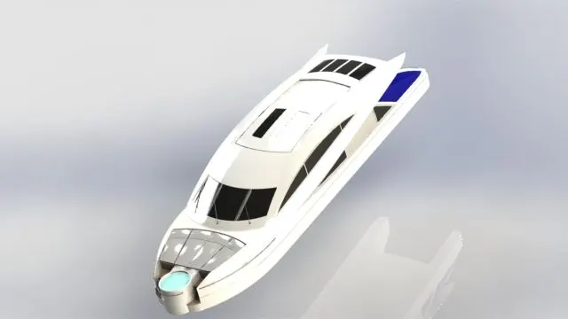
9.radarmast

COMMANDS USED:
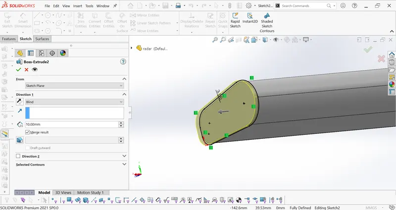
BOSS EXTRUDE:exturdes a sketch or selected sketch contours in one or two directions to create a solid feature.
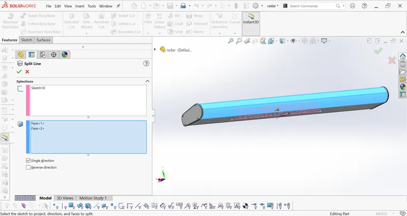
SPLITLINE:The split line tool projects an entity to surface or curved or planar faces.It divides a selected face into multiple separated faces you can split curves on multiple bodies with one command
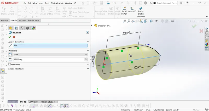
Revolve:Revolve a sketch or selected sketch contours around an axis to create a solid feature
LOFT:Adds material between two or more profiles to create a solid feature
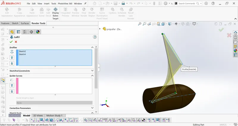
Surface loft:creates a lofted surface between two or more profiles or sketches specify start and end constraints and add guide curves to control the path shape
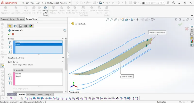
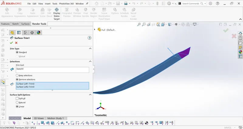
Surface trim:Trims where a surface intersects with another surface a plane or a sketch
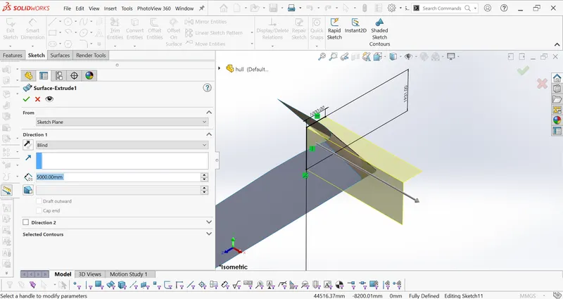
Surface extrude:extrudes a sketch or sketch contours in one or two directions to create a surface feature
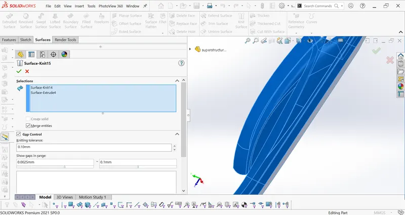
surface knift:combines two or more adjacent non intersecting surfaces into a single surface body.The surfaces must join at an edge .If the resulting knit surface encloses a volume,you can create a solid body
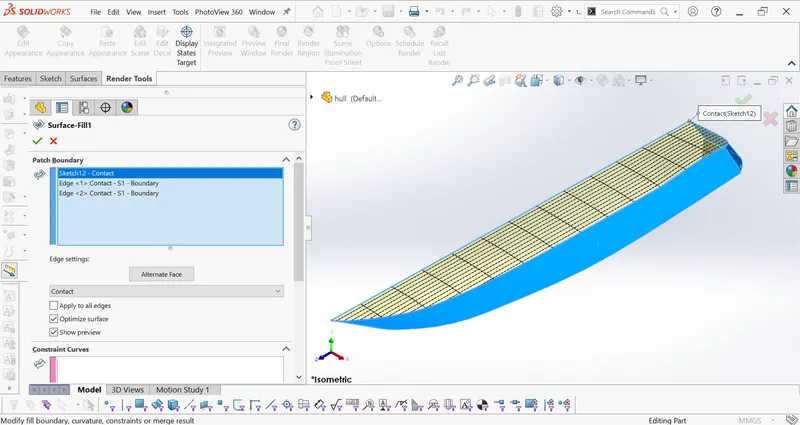
surface fill:Patches a surface with in a boundary defined by edges,sketches,or curves.
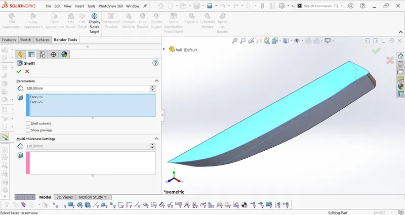
Shell:
The shell tool hollows out a part leaves open the faces you select and creates thin walled features on the remaining faces.If you donot select any face on the model you can shell a solid part creating a closed ,hollow model
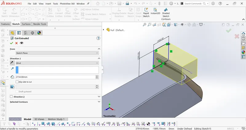
cut extrude:cuts a solid model by extruding a sketched profile in one or more directions
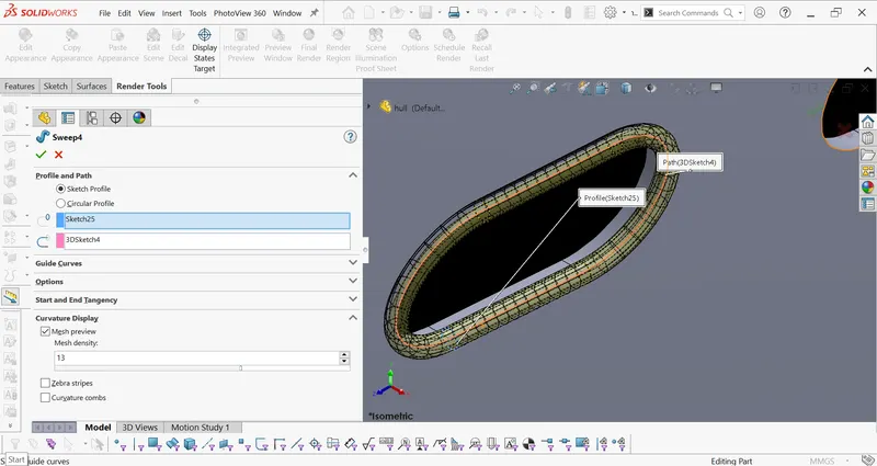
sweep:sweeps aclosed profile along an open or closed path to create a solid feature
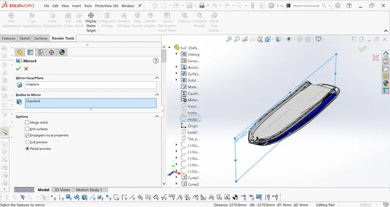
Mirror:Mirrors the feature,faces and bodies about a plane or a planar face
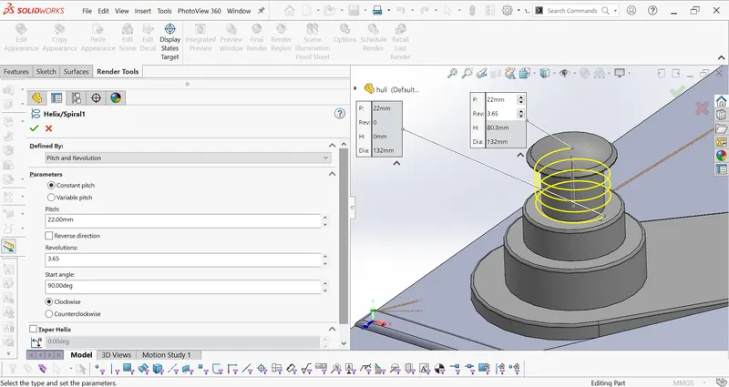
Helix/spiral:It is used for creating helical and spiral curves .we can make sketches of helical curves from a circle in different way by adjusting the pitch and revolution.
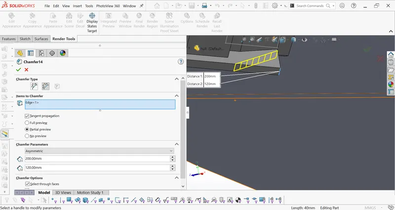
Chamfer:It is one of the useful tool which helps to cut or make edges or corners of 3D models in straight.
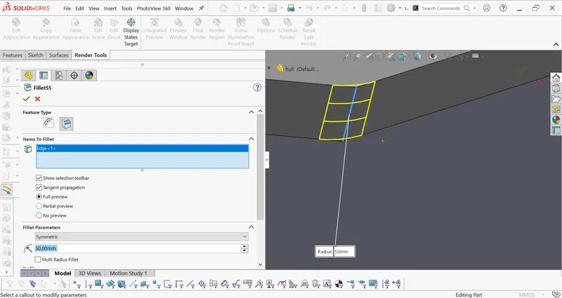
Fillets:IT is a feature which used to rounding of interior or external face along with one or more edges
The fillets are used to reducde the stress concentration effect.
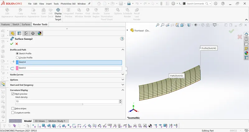
Surface sweep:sweeps a closed profile along an open or closede path to create a suface feature.
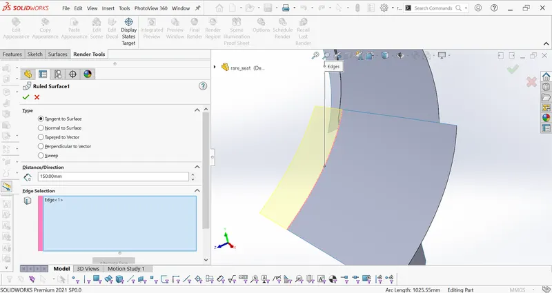
Ruled surface:Inserts ruled surfaces in a specified direction from edges
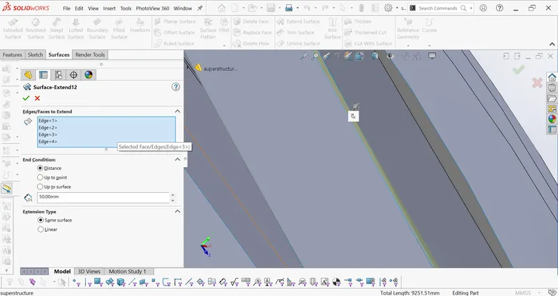
surface extend:extends one or more edges or faces on a surface based on end conditions and extension type
surface offset:offsets surface using one or more contiguous faces .The tool creates an offset surface with gaps.
AND Many more sketch and feature commands are used.The above are the main commands that are used to model the yatch parts
ASSEMBLY OF YACHT:
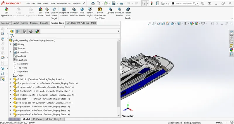
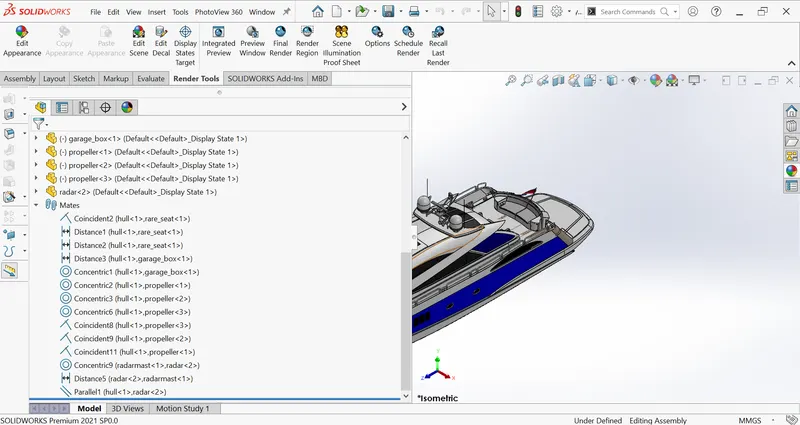
Mates:In assembly we use mates to assemble the parts .
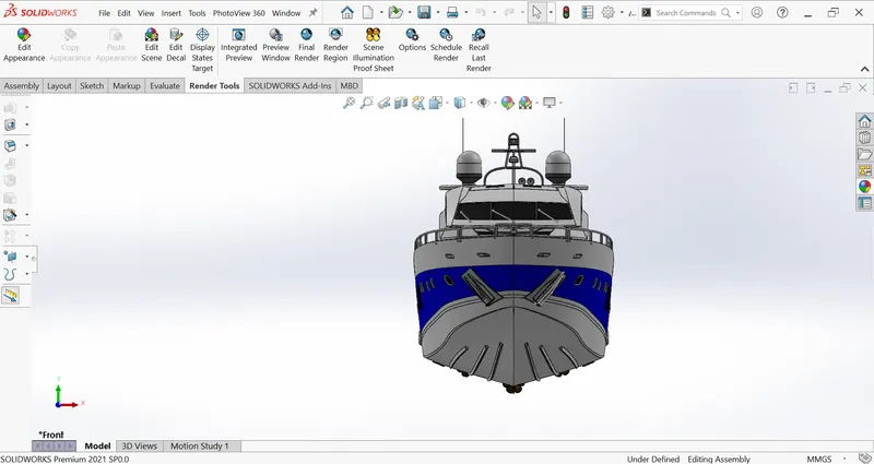
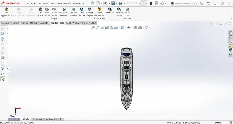
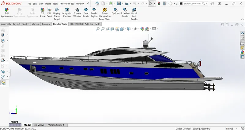
feature tree ,front,top,side and isometric views and mates used:
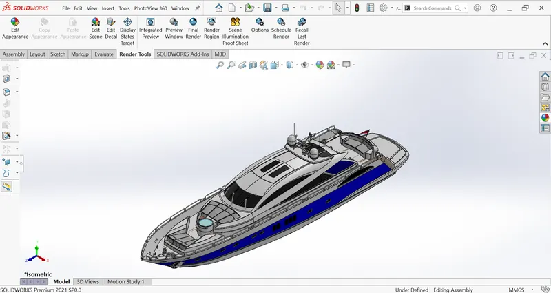
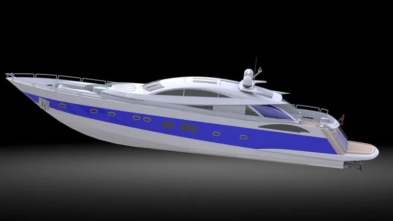
RENDER VIEW:The rendering views are made to make the model to look more realistic as possible
we use solidworks visualization to do the rendering views.
For the detail design of parts and assembly of the parts please refer the files at the end.
CONCLUSION:BY the above procedure we had completed designing the yacht from scratch and we had learned some solidworks features.