Project 2 Adaptive Cruise Control
AIM:Developing Adaptive Cruise Control feature as per the Requirement Document using MATLAB Simulink.
The MATLAB and simulink model for the given requirements is:
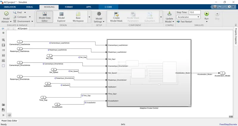
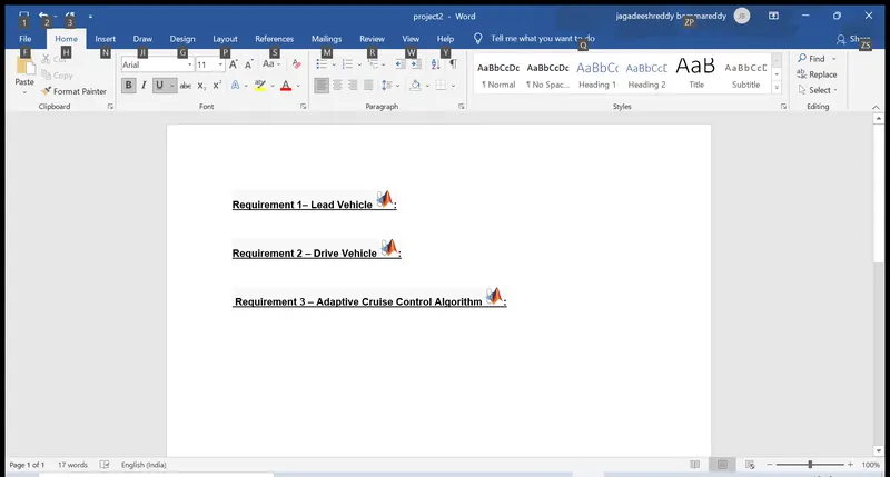
The given requirements with the tags:
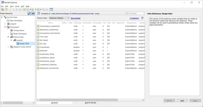
The created Simulink data dictionary is:
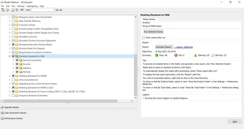
Verifying the model for connections and signal naming as per the standards MAB:
Generating the Software in loop model:
Process:
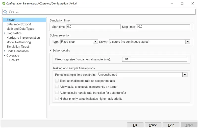
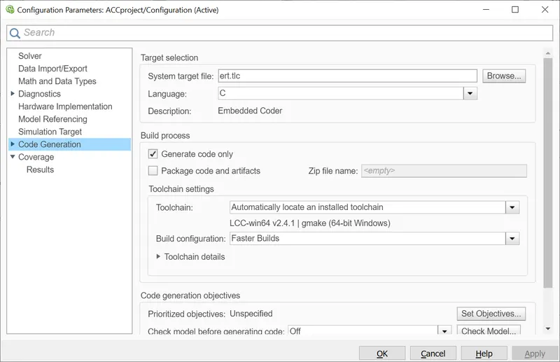
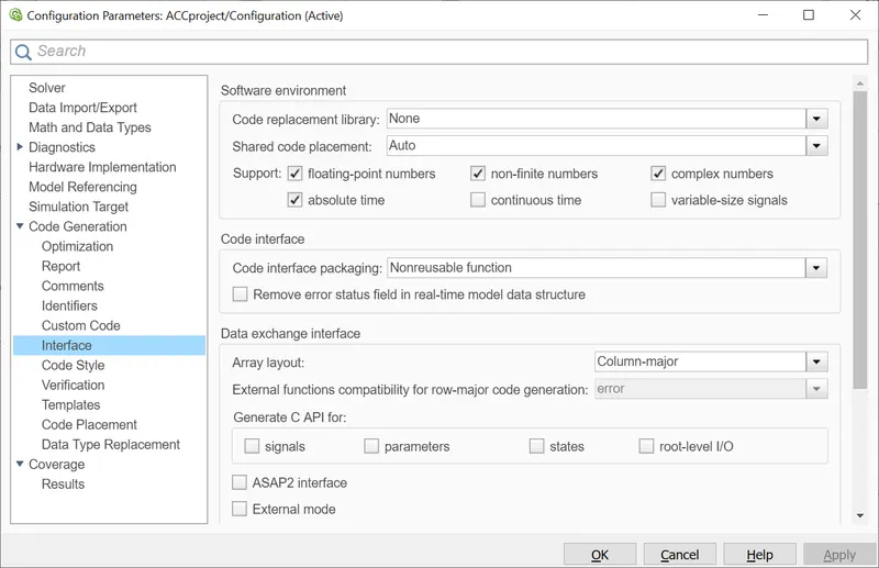
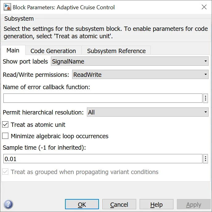
model configuration parameters are:
Creating the Software in loop(SIL) by using harness test:
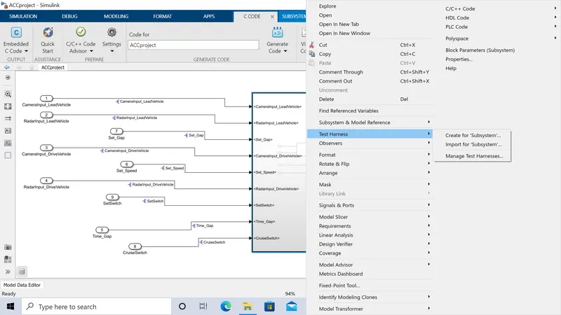
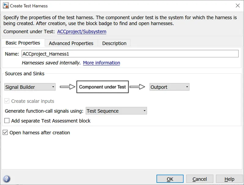
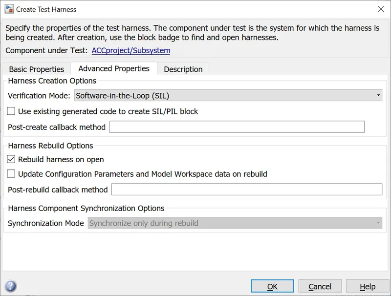
SILtemplate is :
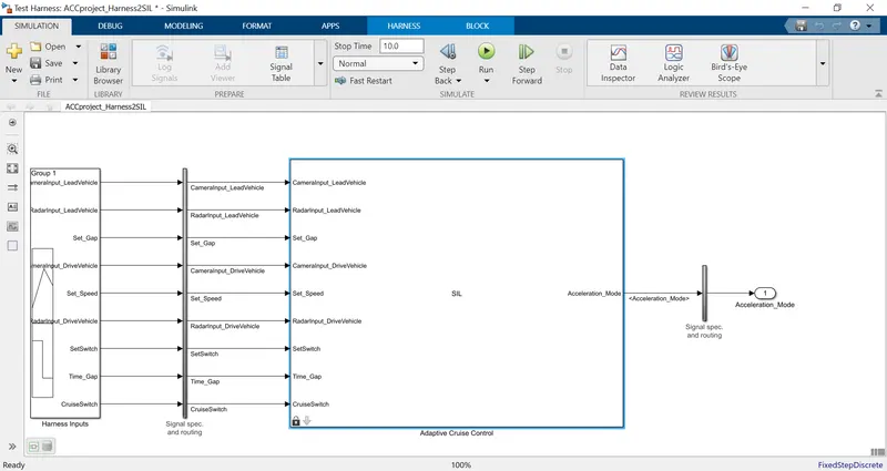
The generated code is:
/*
 * File: ert_main.c
 *
 * Code generated for Simulink model 'Adaptive'.
 *
 * Model version                  : 1.24
 * Simulink Coder version         : 9.3 (R2020a) 18-Nov-2019
 * C/C++ source code generated on : Tue Dec  7 18:51:41 2021
 *
 * Target selection: ert.tlc
 * Embedded hardware selection: Intel->x86-64 (Windows64)
 * Code generation objectives: Unspecified
 * Validation result: Not run
 */

#include <stddef.h>
#include <stdio.h>              /* This ert_main.c example uses printf/fflush */
#include "Adaptive.h"                  /* Model's header file */
#include "rtwtypes.h"

/*
 * Associating rt_OneStep with a real-time clock or interrupt service routine
 * is what makes the generated code "real-time".  The function rt_OneStep is
 * always associated with the base rate of the model.  Subrates are managed
 * by the base rate from inside the generated code.  Enabling/disabling
 * interrupts and floating point context switches are target specific.  This
 * example code indicates where these should take place relative to executing
 * the generated code step function.  Overrun behavior should be tailored to
 * your application needs.  This example simply sets an error status in the
 * real-time model and returns from rt_OneStep.
 */
void rt_OneStep(void);
void rt_OneStep(void)
{
  static boolean_T OverrunFlag = false;

  /* Disable interrupts here */

  /* Check for overrun */
  if (OverrunFlag) {
    rtmSetErrorStatus(Adaptive_M, "Overrun");
    return;
  }

  OverrunFlag = true;

  /* Save FPU context here (if necessary) */
  /* Re-enable timer or interrupt here */
  /* Set model inputs here */

  /* Step the model */
  Adaptive_step();

  /* Get model outputs here */

  /* Indicate task complete */
  OverrunFlag = false;

  /* Disable interrupts here */
  /* Restore FPU context here (if necessary) */
  /* Enable interrupts here */
}

/*
 * The example "main" function illustrates what is required by your
 * application code to initialize, execute, and terminate the generated code.
 * Attaching rt_OneStep to a real-time clock is target specific.  This example
 * illustrates how you do this relative to initializing the model.
 */
int_T main(int_T argc, const char *argv[])
{
  /* Unused arguments */
  (void)(argc);
  (void)(argv);

  /* Initialize model */
  Adaptive_initialize();

  /* Attach rt_OneStep to a timer or interrupt service routine with
   * period 0.01 seconds (the model's base sample time) here.  The
   * call syntax for rt_OneStep is
   *
   *  rt_OneStep();
   */
  printf("Warning: The simulation will run forever. "
         "Generated ERT main won't simulate model step behavior. "
         "To change this behavior select the 'MAT-file logging' option.\n");
  fflush((NULL));
  while (rtmGetErrorStatus(Adaptive_M) == (NULL)) {
    /*  Perform other application tasks here */
  }

  /* Disable rt_OneStep() here */

  /* Terminate model */
  Adaptive_terminate();
  return 0;
}

/*
 * File trailer for generated code.
 *
 * [EOF]
 */
THE PROCESS FOR CODE GENERATION:
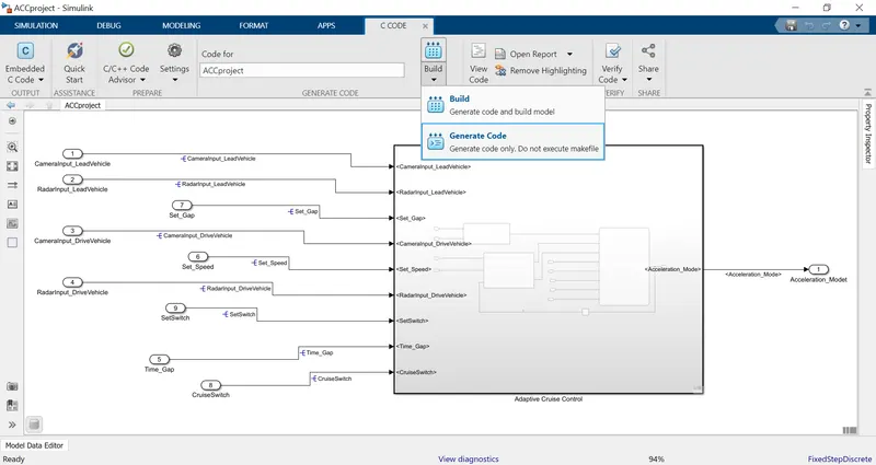
Description:
The logic for the adaptive cruse control is made as per the given requirements,and they aree tagged with the word
Then the inputs to the logic is given by using the Simulink data dictonary the process to create the simulink sldd is explained above.
The ligic signals are given names and signals are resolved and prpagated properly to read the inputs from the SLDD file.
Then the model is tested for the model advisor check to find out any errors in model as per the standards MAB.
IF there are any errors there is chance that the code generation will not take place so check for any errors in the model
If there are no errprs then we go for the code generation process.
The setting and configuration parameters for the code generation process is shown above.
and code is generated by using the process above.
Then an Software inloop template is created by using harness method as showm above these model is tested for the software process by using testing models.like test samples.
Test samples are written based on the logic and the requirements given .