Week 6 Fuel cell powered vehicle model
MATLAB model of fuel cell powered electric vehicle
FUEL CELL :
1.It is a class of device that convert the chemical energy of a fuel directly into electricity by electrochemical reactions.
2.A fuel cell resembles a battery, it can supply electrical energy over a much longer period of time.
3.This is because a fuel cell is continuously supplied with fuel and air (or oxygen) from an external source.
4.whereas a battery contains only a limited amount of fuel material and oxidant that are depleted with use.
5.For this reason fuel cells have been used for decades in space probes, satellites, and manned spacecraft.
6.Around the world thousands of stationary fuel cell systems have been installed in utility power plants, hospitals, schools, hotels, and office buildings for both primary and backup power;
7.Many waste-treatment plants use fuel cell technology to generate power from the methane gas produced by decomposing garbage.
8.Numerous municipalities in Japan, Europe, and the United States lease fuel cell vehicles for public transportation and for use by service personnel.
9.Personal fuel cell vehicles were first sold in Germany in 2004.
10.let us see an example of Proton exchange membrane (PEM) fuel cell
11.The proton exchange membrane is one of the most advanced fuel cell designs.
12.Hydrogen gas under pressure is forced through a catalyst, typically made of platinum, on the anode (negative) side of the fuel cell.
13.At this catalyst, electrons are stripped from the hydrogen atoms and carried by an external electric circuit to the cathode (positive) side.
14.The positively charged hydrogen ions (protons) then pass through the proton exchange membrane to the catalyst on the cathode side.
15.where they react with oxygen and the electrons from the electric circuit to form water vapour (H2O) and heat.
16.The electric circuit is used to do work, such as power a motor.
FUEL CELL ELECTRIC VEHICLE:
1.Let us consider an inbuilt fuel cell vehicle in the matlab
2.The command for it is power_fuel_cell
3.The block diagram of the vehicle is
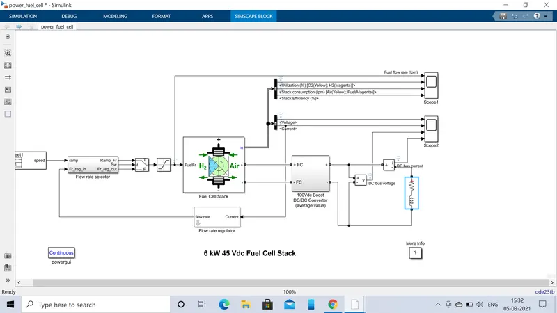
The block mainly contains
1.signal builder block
2.flow rate selector
3.fuel cell block
4.flow rate regulator
5.DC/DC converter
6.Series RLC branch
Description:
1.The above model is an Proton Exchange Membrane (PEM) Fuel Cell Stack model feeding an average value 100Vdc DC/DC converter.
signal builder block is used to give the required input signal that is the actual driving conditions of the car the drive cycle.since it converts one form of signal to the other form
flow rate selector:
it is used to compare the input signal and the flow of the hydrogen and as per the drive cycle the flow of the fuel is sent into the fuel cell
fuel cell block:
In the block we use an proton exchange membrane fuel cell with an stack voltage of 45V DC and an nominal power of 6KW .in this the fuel hydrogen that is entered into the fuel cell will be converted into an water as described above
The voltage generated will be based on the flow rate selector as it regulates the flow of the hydrogen
This block can be used for model of solid oxide fuel cell,Alkaline fuel cell.
Flow rate regulator:
It compares the out put current and the flow of the hydrogen and it sents the required amount of hydrogen to the flow selector as meet the out put demand current.
The drive cycle that we used is UDDS
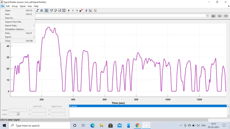
results:
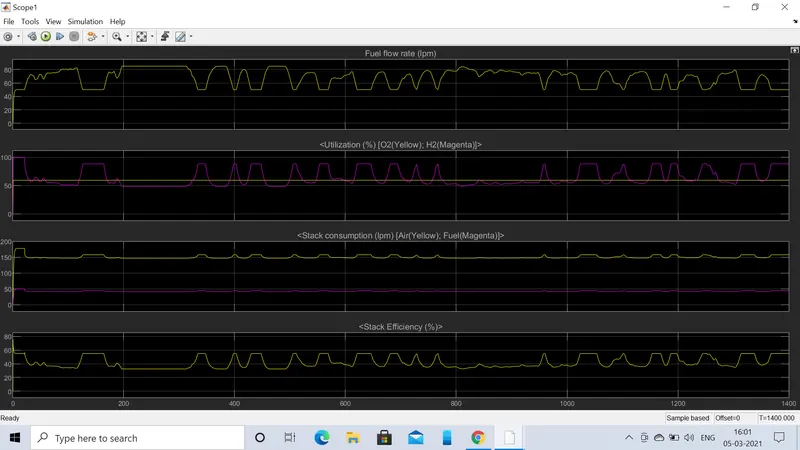
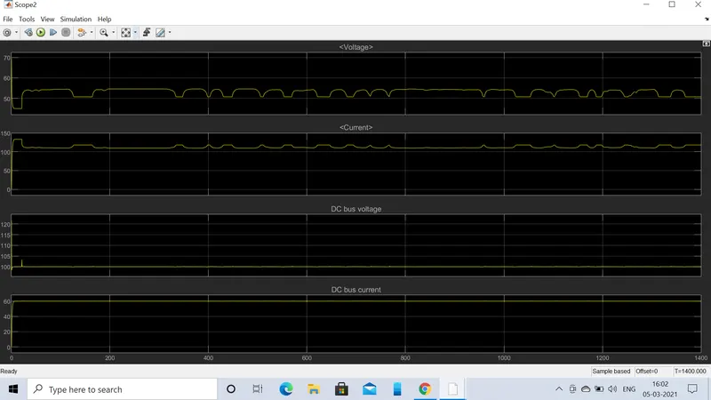
observations:
explanation:
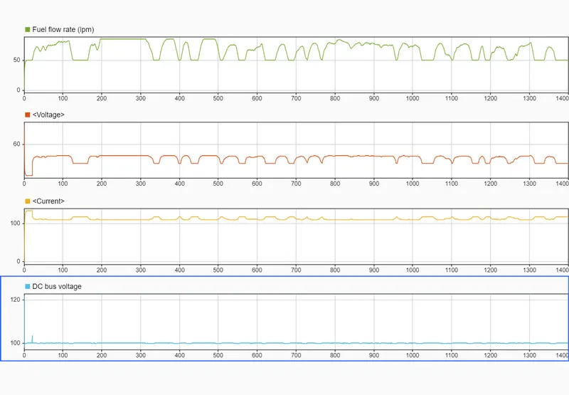
1.From the above graphs we can see that the the fuel flow rate maches with the drive cycle ,the voltage generated is also same as that of the drive cycle and fuel flow rate.
2.the current generated is opposite to that of the voltage generated
3.As the speed increases the fuel flow to the fuel cell increases and the voltage generated increases and current decreases.
explanation:
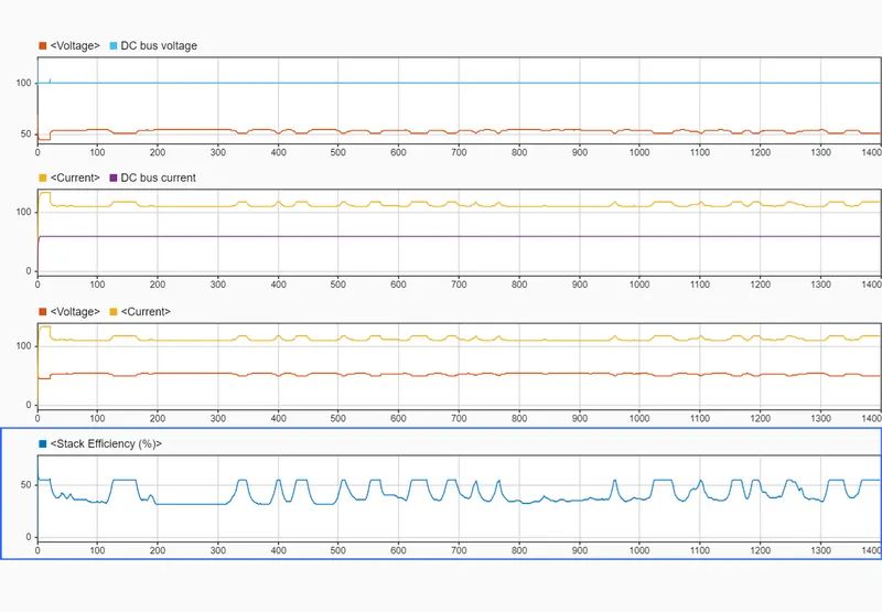
1.When we compare with the generated voltage ,current with the DC bus voltage and current.
2.The generated out put voltage is lower than the DC bus output voltage and the generated current is higher than the DC bus current and the over all power is maintained constant.
explanation:
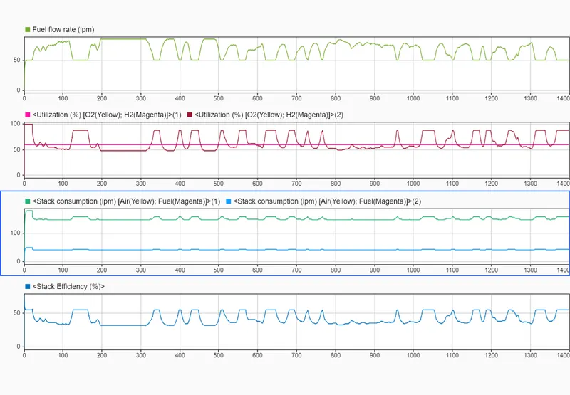
1.The stack efficiency of the cell decreases as the speed increases
2.The %utilization of the H2 decreases as the speed increases and the stack consumption decreases i.e the air and the fuel is not used properly .