Project 1 Mechanical design of battery pack
Battery pack construction of capacity 18kw by using the cell ANR26650M1-B :
ASSUMPTIONS:
1.Let us assume that this battery pack is used for electric vehicle.
2.battery efficiency as 99percent.
3.low density polyethylene is used as module and holder material.
4.sigmaclab40 is used an connector material.
5.steel is used as an pack structure material.
CELL Details:ANR 26650 M1B
Nanophosphate cell,lithium iron phosphate cell
chemistry:LiFepo4
Anode:allunimium
cathode:nickel
round shaped cell

Features
| Model # | ANR 26650 M1B |
| Nominal Voltage | 3.3V Nominal, |
| Nominal Capacity | 2500 mAh (at 0.2C rate, 3.65 +/-0.05V cut-off) |
| Energy Density | 108.10Wh/kg |
| Charging current |
|
| Discharging current |
|
| Temperature Range |
|
| Cycle Performance | >1000 (100% of initial capacity at 20A discharge) |
| Dimensions(DxH) | 26mm(1.0") x 65.15 mm(2.6") |
| Weight | 2.9Oz (76 grams) |
| Tab Option | The tab (part# TB-DHT) can support surge discharge at 100A |
| Certification | UL#MH45042 |
2.The design of a battery pack is done based on the standard of SAE J2289
3.SAE J2289: It describes practices for design of battery systems for vehicles that utilize a rechargeable battery to provide or recover traction energy.
4.The battery pack construction is done in a step by step process
5,The steps involved inthis process are
a)voltage and current calculations to get the required energy
b)cell
c)module
d)cell and module connections
e)pack construction
f)sensors
g)Battery Management System
h)thermal management system
i)vibration and crash
j)safety standard
a)voltage and current calculations:
Let us assume the voitage required be 330V for EV
the battery pack capacity is 18000W
no of cells required in series= 330/3.3
=100
since when the cells are connected in series the voltage will increase.
no of cells required in parallel=18000/330=54.5
=54.5/2.5
=21.8=22cells
therefour 100S22P 100 cells are connected in series and 22 cells are connected in parallel to get the required battery capacity with required voltage and current.
The total number of cells inthe pack are 2200 cells these are divided into small modules for better management of the battery.
Our battery pack contains 4 modules with 25S22P each with total no of cells are 550 cells,and total no of cells are 2200cells.
Each module has an voltage of 82.5V and 55Ah total capacity of 4537.5W
The 4modules combines give 18150W of capacity battery pack.
MODULE:
The battery module is constructed by assembling the cells in an order way.
let us see the cell arrangement
geomentry of the cell is :
dia of cell =26mm
height of cell=65.15mm
In the module 25 cells are arranged inseries with 4mm gap between them and 22 cells are arranged in parallel with 4mm gap between them
All the cells are hold to gether with the help of plastic holders by tietly fitting the battery in the holder

The above shaped 25*22 battery holders are used for holding the cells to gether.
A gap of 4mm is maintained between the cells for passing of more air between the cells this will help in increasing the battery life by reducing the heating effect since the air can remove the heat generated by carrying it out.
cell conncetions:
The connection between the cells is done by using the material SIGMACLAD
The thin sheet like SIGMACLAD40 material is spot welded to the terminals of the battery
SIGMACLAD40 is a composite material with copper nickel and stainless stell combined to gether
It is used because it has a better thermal property.it generate very less heat when compared with pure metals like nickel.
sensors :
Alluminium based foil conncetions are used for sensing the voltage,current, temperature and these are connected to the battery management system.
These are used since they are easy to handle and are easy to assemble .
We can use a fuse at the cell level for better battery management system.
Battery management system:
The battrey management system is used to maintain the all the cell voltages and currents at equal and it helps in increasing the life of the battery pack.
All the sensors that are connected in the battery are connected to the battery management system
The battery management system is a programed system it helps in protecting the cells being damage due to abuse of failure cases.
It helps in detecting the unsafe conditions and helps the operater to operate in the safer limits.
IT helps in maintaing the temperature limits when ever cooling or heating is required.
Thermal management system:
1.foil based tubes are constructed under the module and these are used to heat or cool the battrey module based on the temparature limits.These coils are connected to the Thermal management syatem with heat source and a coolent .
2.It helps in improving the performance of the battery since the battery does not perform well when the temperature limits are out of the limits.
3.Small FAN and pressure equilizer is mounted on the shell of the module for removing the gases and maintaining the pressure equilibrium with the temperature.
MODULE SHELLS:
Plastic material is used as an shell for placing all the cells and sensors inside it.
pack construction:
1.All the 4 modules are constructed in a similar way and these are connected in series .
2.The conncetion between the modules are done by using the copper-nickel composite material with pin type connections.
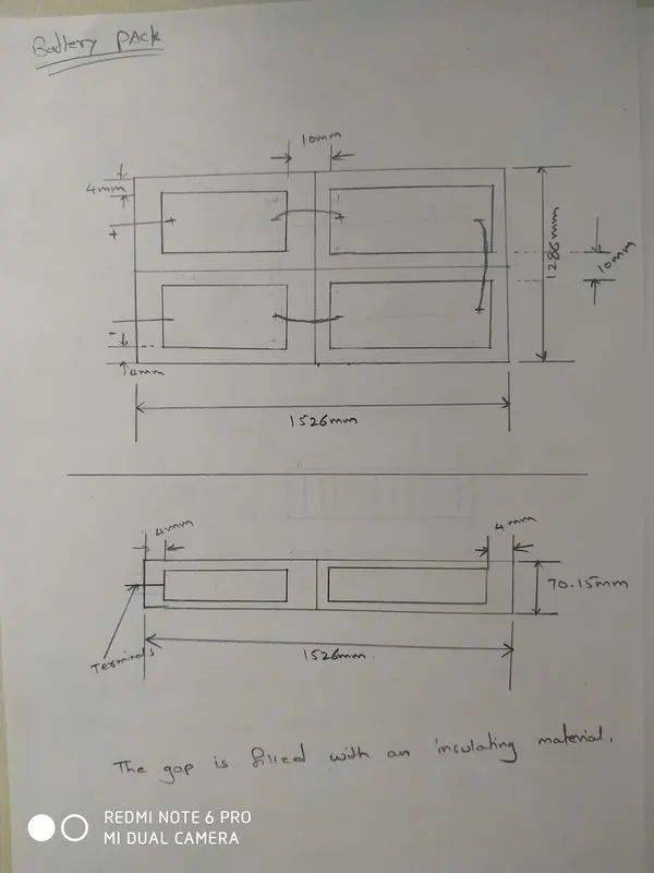
3.The modules are sepearted with each other by using a insulation material.To avoid thermal and short circuit problems.
4.The 4 modules are connected very tightly with out any movement of the module.
5.The pack construction is done basically by using steel material since it has high strength and better thermal conductivity for heat transfer.
6.All the BMS and TMS inside the pack are connected to the single BMS system for overall management of the pack.
7.The steel box is welded for the construction as per the required shape.
8.The battery pack is provided with an cooling fan and a pressure equilizer.
Vibration and crash :
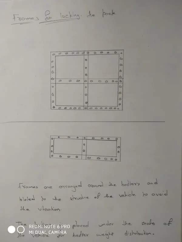
1.To avoid the vibration the pack is attached to the body of the vehicle with the help of frames that are made around the battery pack.
2.These frames also helps in crash to avoid the battery damage.
3.SAE J2380 standard is used for the reduction of vibration of the battery pack.
SAFETY:
1.SAE J 2344 are followed for the safety standards the pressures and the gasses generated are released safely and short circuit problems are avoided etc.
CALCULATION OF WEIGHT:
CELL:
Total no of cells=2200
weight of each cell=76grams
total weight =2200*76=167200grams=167.2kgs
HOLDERS:
low density polyethylene material is used
density=913kg/m3
volume=0.034*0.034*0.004=4.62*e-6
each cell has 2 one at top and one at bottom=9.248*e-6
total no of cells 2200=9.248*2200*e-6=0.0203
weight=0.0203*913=18.5kg
connectors :
plate lilke sigmaclab40 is used with a thickness 2.5mm
density of sigmaclab40=8415kg/m3
for module
length=gaps+dia+clearence
=24*4+25*26+4=750mm
width=gaps+dia+clearence
=21*4+21*26+0=630mm
thickness=2.5mm
these are spot welded
volume=0.750*0.630*0.0025=0.00118
weight=0.00118*8415=9.940
on both sidea of the cell=9.940*2=19.88kg
for each module the connector weigth=19.88kg
for all the 4 modules the weigth,i.e the pack level =19.88*4=79.52kg
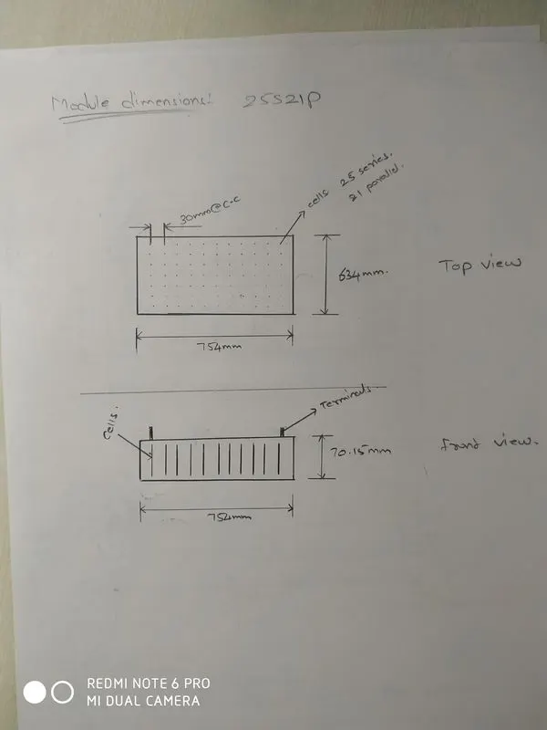
module dimensions and weight:
low density polyethylene is used since it has more thermal conductivity and thickness=2mm
25S21P
Length=gaps+cells+clearence
=24*4+25*26+8
=754mm
width=gaps+cells+clearence
=20*4+21*26+8
=634mm
height=65.15+2.5+2.5(height of cell+connecting plates up+down)
=70.15mm
volume=length side=0.754*0.07015*0.002=0.0001057
weight=0.0001057*913=0.096582*2=0.1931kg
width side=0.634*0.07015*0.002=0.0812*2*913=0.1624kg
weight for each module=0.355kg
total weight for 4 modules=0.355*4=1.42kg
pack dimensions and weigth:
steel material is used for the construction of pack
dimensions,length=module length+module length+gap+clerance=754+754+10+8=1526mm
width=module width+module width+gap+clerance=634+634+10+8=1286mm
height=heigth =70.15
thickness of sheet=2mm
density of steel=7500kg/m3
weigth of the sheet =5.916kg
let us consider auxilaries like fan and equlizer weigth as 500grams
mislinious weigth example=supporting frames and some =6kg
total weight of battery pack=cells+holders+connectors+modules+pack+auxilaries&misslanious
=167.2+18.5+79.52+1.42+5.916+0.500+6
=279.056=280kg
Therefore the overall weight of the battery pack is nearly=280kg
The battery output voltage =330V
current=55Ah
total capacity=18150W
efficiency=0.99
specific energy,Wh/kg=18000/280=64.28Wh/Kg
energy density,Wh/L=18000/0.1376*1000=130.8Wh/L
placement of a battery
The battery is placed under the seates of the vehicle for bettery weight distrubtion .and to maintain the balance of the vehicle.
The structure of the battery will look like as follows: