Week -2
Making a Simulink model of Doorbell using solenoid block :
The simulink model is
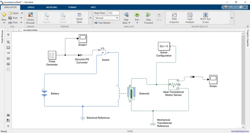
The blocks we used are
1.Pulse generator
2.battery
3.switch
4.solenoid
5.ideal translational motion sensor
6.solver configuration
7.electrical referance
8.mechanical referance
9.scope
10.simulink ps converter
electrical connections:
The battery and switch are connected to the solenoid
mechanical connections:
To observe the moment of the R and c in the solenoid an ideal translational motion sensor is conneted to it .
Generation of the signal:
To generate the signal for 2seconds as required a pulse generated is used and an simulink ps converter is used to convert simulink signal to physical signal.and it is connected to the switch .The output from the pulse generator can be seen by using scope connected to it
The electrical and mechanical referancess are connected to the electrical and mechanical connections as a referancess for solving the connections.
solver configuration is used to solve the connections as an equation.
WORKING:
AS the pulse generator generates the signal it is converted to the physical signal and fed to the switch as the switch is on the current flows through the solenoid and R and c starts moving .
When they move the motion of these are senced by using the ideal translational motion sensor and an output is taken at the scope.
The motion of the R and C is consider as the moment of Bell and the metal arm for producing the sound.
RESULTS:
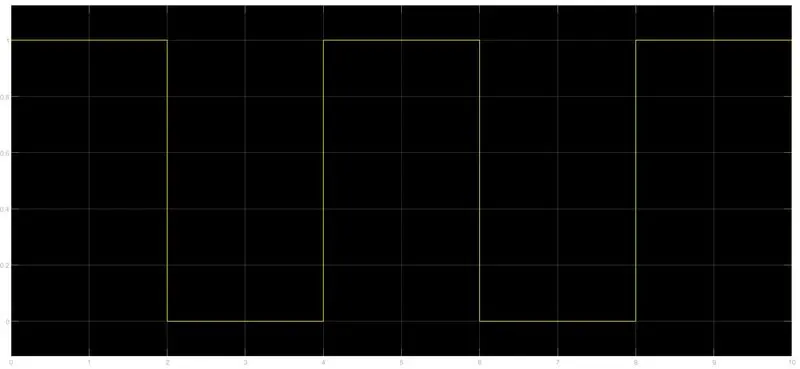
INPUT SIGNAL:
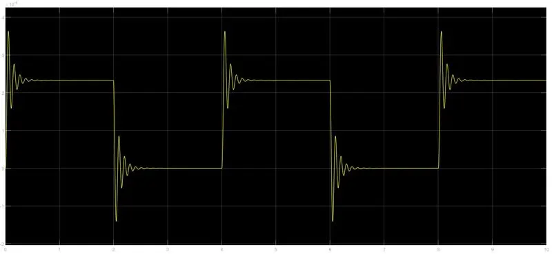
OUTPUT signal:
observations:
From the above input results we can see that for every two seconds the power gets on and off through the solenoid
From the above output results we can see that at every on and off stage there is buzzer occuring by this we can say that the bell produce sound by attracting the metal at every state .
2A)Thermistor to sense the temperature of a heater & turn on or turn off the fan:
The simulink model is
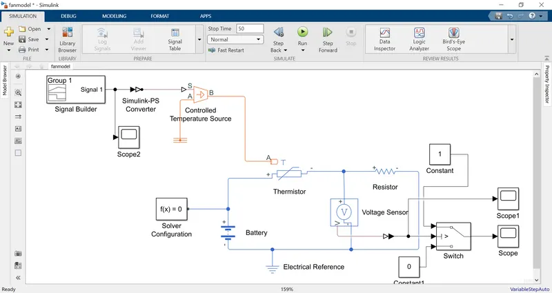
The blocks used are
1.signal bulider block
2.simulink-ps converter
3.controlled temperature source
4.Thermistor
5.Battery
6.Resistor
7.Voltage sensor
8.switch
9.constant blocks.
10.solver snd electrical referances
11.scopes
Connections:
Thermister and resister and an battery are connected in series and an voltage sensor is connected across the resistor to measure the voltage in the resistor.
Controlled temperature source is connected to the thermister to control the temperature .
conditonal switch is connected to the voltage sensor and two constants and output is taken at the scope
INPUT signal:
Signal builder block is used to generate the required signal as per the requirement .It converts the physical signal to simulink signal .A graph is generated inthe signal builder block as per the requirement the given is an celcious but the blocks takes in kelvin scale the required input graph is
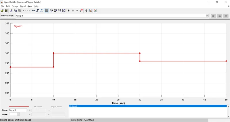
The ouput from the block is
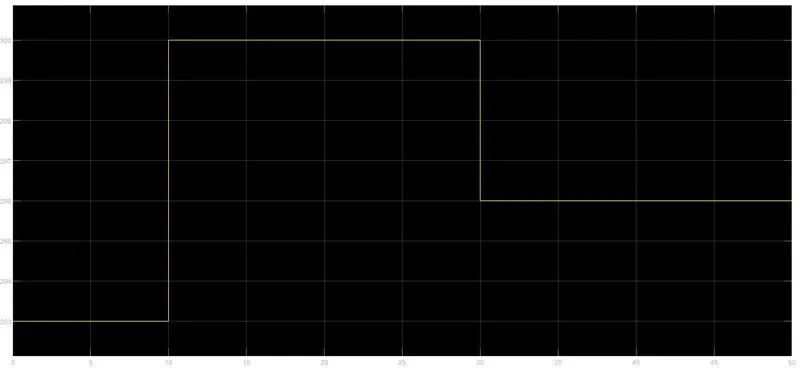
This is given as an input to the Controlled temperature source.for connecting the signal builder block and controlled temperature source an simulink and physical converter is used.
The simulation is runed for 50 seconds as per the requirement
The voltage across the resistor is observed the voltage is
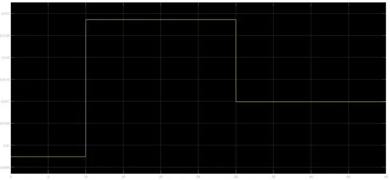
The above graph gives us the generated voltage for thr required temperature
The switch is used for geting the output observing one as an onstate and zero as an off state.
As per the requirement i.e 25C it is 298K temperature the voltage is 0.012V This value is used as an therhold value for the switch
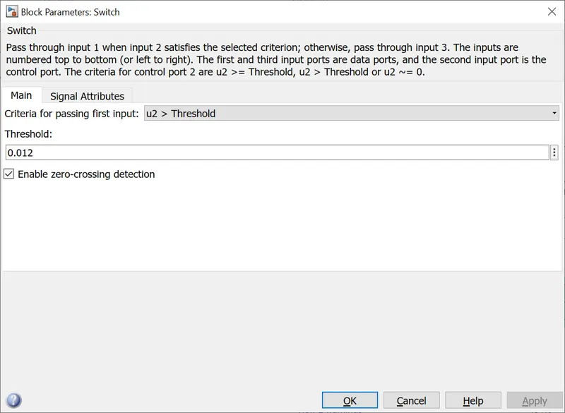
above the thershold value the switch get on
The output RESULT:
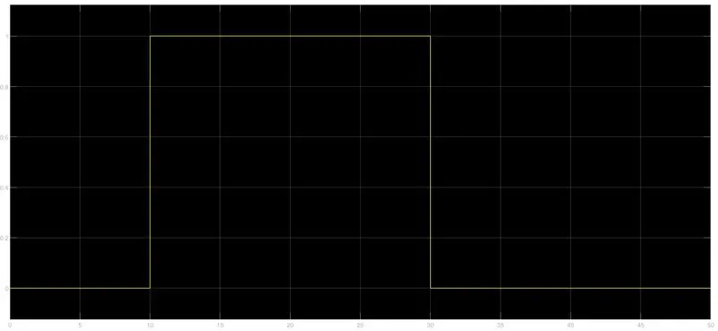
From the above graph we can see that when the temperature is above 25C the fan gets on and when the temperature is below the 25C the fan gets off as per the requirement.