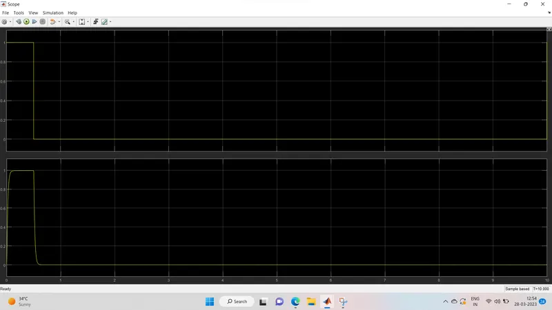
Project - Position control of mass spring damper system
Obtain the transfer function of a mass spring damper system and use it in the model. Add a PID controller to adjust the force on mass so that its position follows a reference signal.
Take m = 3.6; %kg k = 400; %N/m c = 100; %Ns/m
The reference signal is shown in the following figure.
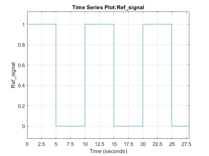
Given Data:-
m = 3.6 kg
k = 400 N/m
c = 100Ns/m
Transfer function for a spring mass damper system is 1/(m*s^2+c*s+k)
where m is mass, c is damping coefficient and k is spring constant.
after subtituting the respective values in the transfer function
1/(3.6*s^2+100*s+400)
% Design Parameters

m=3.6;                                                 % Mass
k=400;                                                 % Spring Constant
c=100;                                                 % Damping constant
wn=k/m;                                              % Angular Frequency
f=wn/2*pi;                                           % Frequency
zeta=0.9;
p1 = -zeta*wn+wn*sqrt(zeta^2-1);      % 1st Pole
p2 = -zeta*wn-wn*sqrt(zeta^2-1);       % 2nd Pole
P = [p1;p2];                                        % Vector containing poles

% A & B matrices

A = [0 1;-k/m c/m];
B = [0;1/m];

% Poles placement design

K = place (A,B,P);

Kp = K(1);
Kd = K(2);
Ki= 11000;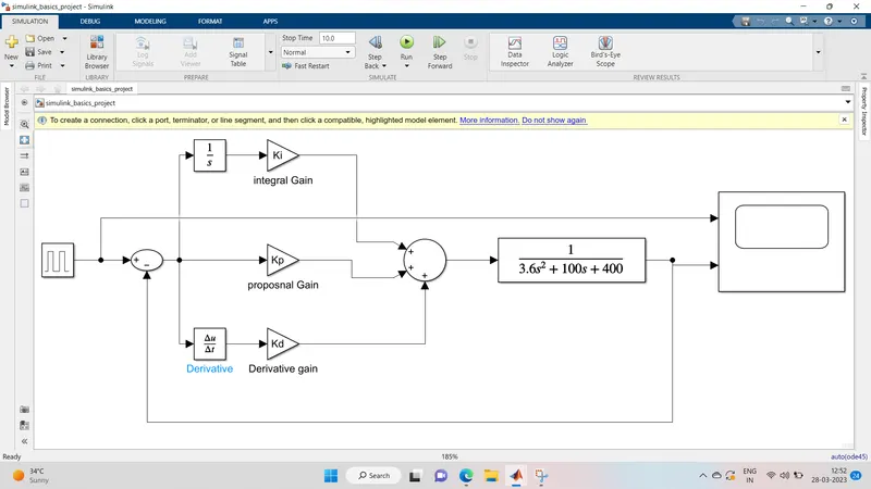
In this model, we have used a Pulse generator as the reference signal. Two mathematical operators blocks are used to conduct mathematical operations. Three gain blocks are used for the Integral(Ki), Proportional(Kp) and Derivative gains(Kd) respectively. One integrator block is used to integrate the signal and one derivative block is used to differentiate the signal. A transfer function is used to function as the spring mass damper system with respective co-efficients. This makes the model much clear.