Project 2 - Modeling of 3 phase Induction Motor Drive
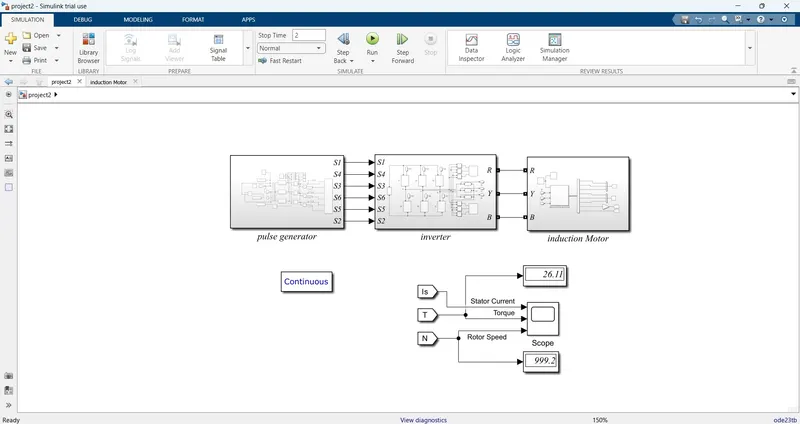
AIM: - The main aim is Design the 3 Phase Inverter using Simulink and Controlling the 3 phase Squirrel Cage Induction motor, using V/F method from 3 Phase Inverter.
Answer: - Three-phase inverter is used to change the DC voltage to three-phase AC supply. Generally, these are used in high power and variable frequency drive applications.
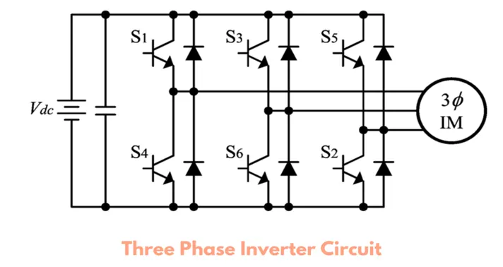
Generally, the three arms of this inverter will be delayed with 120 degrees angle to generate a 3 phase AC supply.
The switches used in the inverter have 50% of ratio and switching can be occurred after every 60 degrees angle. The switches like S1, S2, S3, S4, S5, and S6 will complement each other. In this, three inverters with single-phase are placed across a similar DC source. The pole voltages within the three-phase inverter are equivalent to the pole voltages within the half-bridge inverter with a single phase.
V/F control: - V/f control is a method to control a ratio between primary voltage (V) to be applied to the induction motor and
inverter output frequency (f) to be constant. This control enables to obtain satisfactory torque characteristics in a wide
frequency range by maintaining the magnitude of the rotating magnetic field vector independently from the inverter
output frequency when voltage drop due to a primary winding resistance is ignored.
However, as the frequency declines, the voltage drop due to the primary winding resistance becoming too large to be
ignored, and consequently, it becomes impossible to obtain sufficient torque. In such a case, applying a higher voltage
than the voltage calculated from the V/f ratio which was used for a high frequency makes it possible to secure enough
torque even at a low frequency.
Whenever three phase supply is given to three phases induction motor rotating magnetic field is produced which rotates at a synchronous speed given by

In three phase induction motor emf is induced by induction similar to that of a transformer which is given by

Where,
K is the winding constant
T is the number of turns per phase
f is frequency.
Now, synchronous speed varies as frequency is changed, but when frequency is decreased, flux increases. This change in flux value results in saturation of the rotor and stator cores, which further raises the motor's no-load current. Hence, maintaining flux at a consistent value is crucial, and doing so requires changing the voltage. In other words, if we lower the frequency, the flux will increase, but if we lower the voltage, the flux will drop as well, creating no change in flux and keeping it constant. Hence, we are maintaining a constant V/f ratio here. As a result, it is called the V/f approach.
Simulation: -
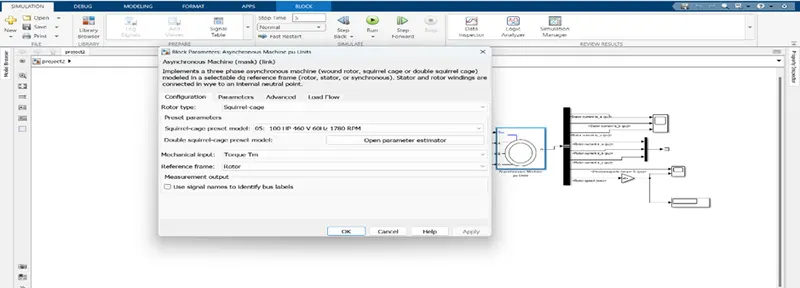
Motor prameters:-
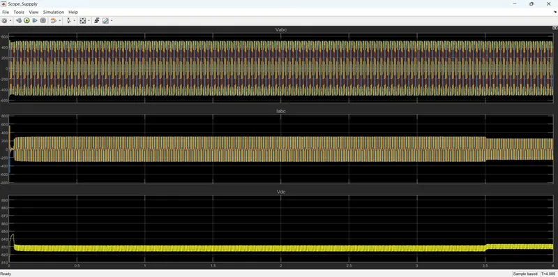
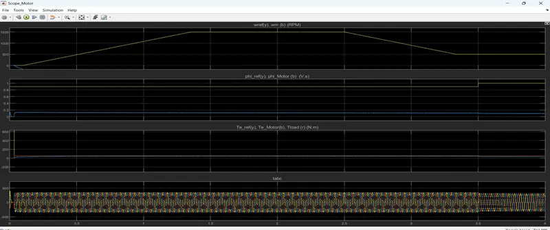
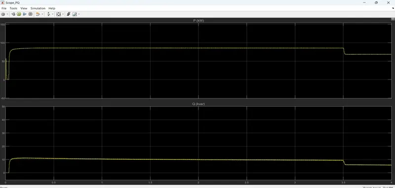
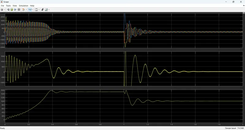
Simulation result: -
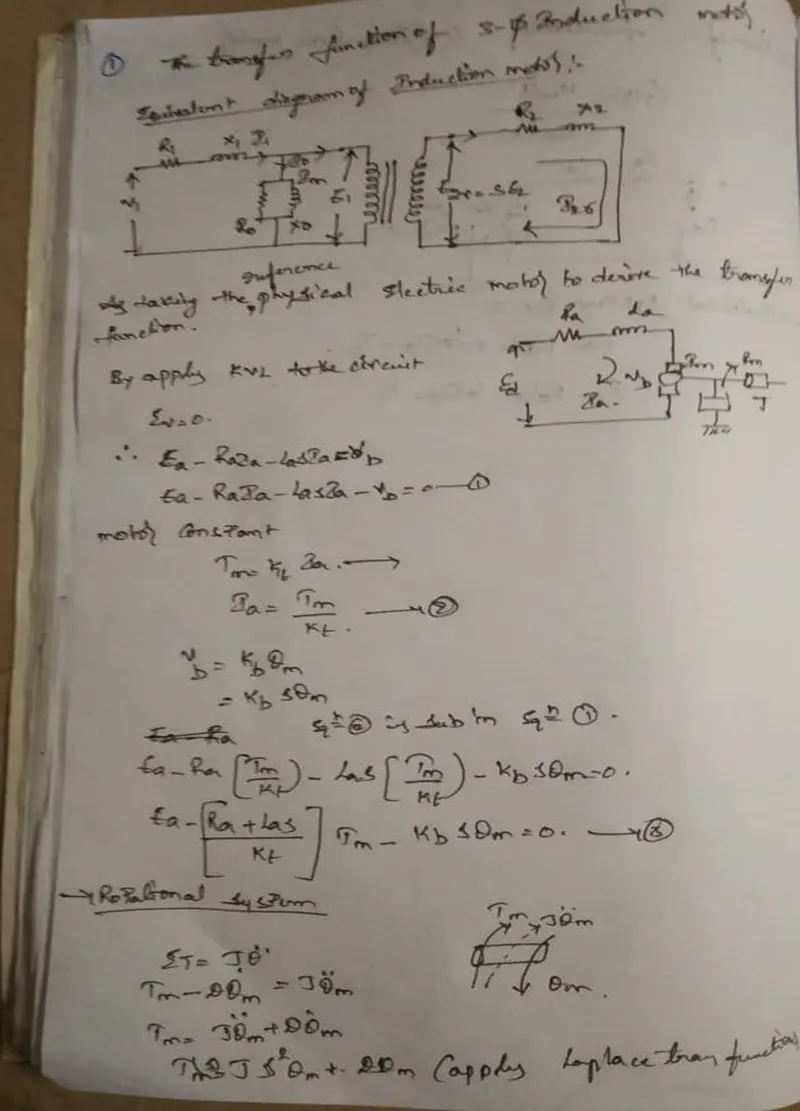
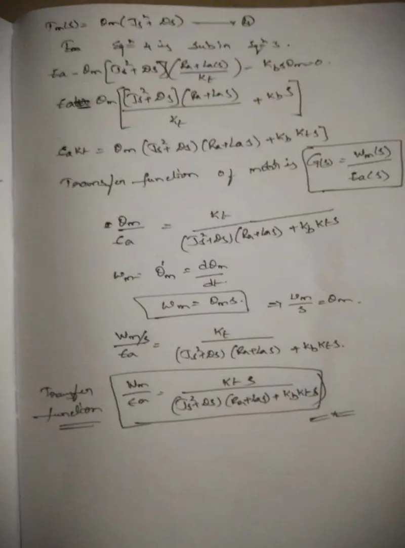
Use the 3-phase inductor motor theory to derive the transfer function of 3 phase Induction Motor
To derive the transfer function of a three-phase induction motor, we start with the equivalent circuit of the motor. The equivalent circuit of a three-phase induction motor can be represented as follows:
- R1 is the stator resistance.
- R2 is the rotor resistance.
- R'2 is the rotor resistance referred to the stator side.
- X1 is the stator leakage reactance.
- X2 is the rotor leakage reactance.
- Xm is the magnetizing reactance.
- E1 is the applied voltage per phase.
- E2 is the induced voltage per phase.
- I1 is the stator current per phase.
- I2 is the rotor current per phase.
- I'2 is the rotor current referred to the stator side.
- Model 3 phase induction motor with a 3-phase inverter using Direct Torque control using an Average Model, implement both torque and flux control to achieve desired power.
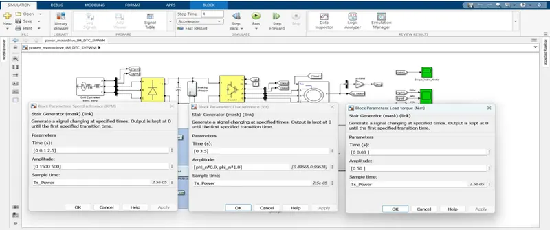
Design Parameters:
- Initial Speed = 0 RPM
- Flux Target = 2.5 Weber’s
- DC Voltage = 500 V;
- Fundamental Frequency = 60 Hz
- Speed Step Time = 0.01 secs
- Determine fundamental speed based upon fundamental frequency
- Determine the switching sequence for direct torque control
- Moment of Inertia = 0.1 Kgm^2
- Load Torque Initial = 0 Nm
- Final Load Torque = 50 Nm
- Torque Step Time = 0.03 secs
Motor Parameters: (Create an Average Model)
- Stator Resistance = 0.5 Ohms
- Rotor Resistance = 0.2 Ohms
- Stator Leakage Inductance = 20 mH
- Rotor Leakage Inductance = 10 mH
- Magnetizing Inductance = 200 mH
- Number of Poles = 4
- Torque to Speed
SVPWM-Based Direct Torque Control (DTC) of an Induction Motor Drive is a control technique that is used to improve the performance of induction motor drives. It is a combination of two different control techniques: Space Vector Pulse Width Modulation (SVPWM) and Direct Torque Control (DTC).
In SVPWM, the input voltage is synthesized using a set of switching pulses generated by a pulse width modulation (PWM) technique. The PWM technique is based on a combination of three-phase voltage vectors, which are generated based on the reference voltage vector and the location of the output voltage vector in the voltage space vector diagram. The switching pulses are generated by comparing the reference voltage vector with the triangular carrier signal.
In DTC, the torque and flux of the induction motor are controlled directly, without the need for a separate current control loop. The DTC technique uses hysteresis controllers to generate switching signals for the inverter. The hysteresis controllers compare the actual and reference values of the flux and torque, and based on the error signal, generate the switching signals for the inverter.
In SVPWM-Based DTC, the SVPWM technique is used to synthesize the input voltage for the inverter, while the DTC technique is used to control the torque and flux of the motor. The reference voltage vector for SVPWM is obtained based on the reference values of the torque and flux, which are generated by the DTC controller. The switching signals for the inverter are generated by comparing the reference voltage vector with the triangular carrier signal.
The SVPWM-Based DTC technique has several advantages over conventional DTC techniques, including faster dynamic response, better steady-state performance, and reduced harmonic distortion. However, it is more complex and requires more processing power than conventional DTC techniques.
Simulation: -
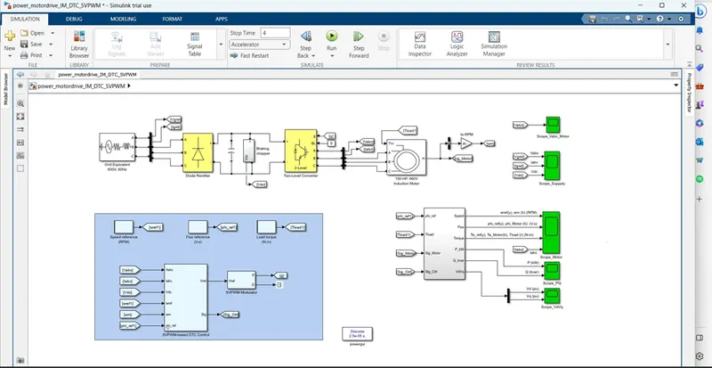
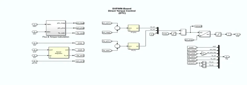
motor design
- Stator Resistance = 0.5 Ohms
- Rotor Resistance = 0.2 Ohms
- Stator Leakage Inductance = 20 mH
- Rotor Leakage Inductance = 10 mH
- Magnetizing Inductance = 200 mH
- Number of Poles = 4.
Simulation result: -