Project 2 Adaptive Cruise Control
Aim of Project:- Adaptive Cruise Control Feature provide passenger cars driver better controlling and hadelling vehical in easy way. For this controlling controller required some signal like Camera Input ,radar Input,Set speed, Set gap,Cruise Switch position, Set switch, Lead vehical speed,Drive vehical speed this signal help to calculating and provide controlling sitation according for effective output.
Simulation Model:-
For this project creating Subsystem block.
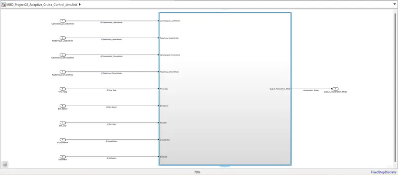
In this Subsystem contain 3 Subsystem block according the requirement.
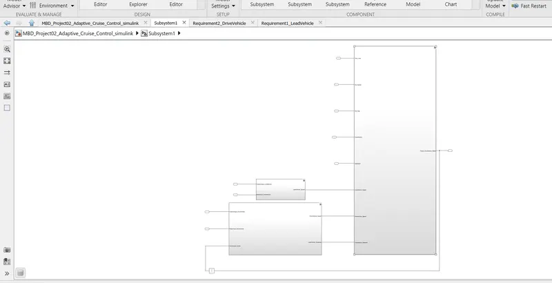
Development of MATLAB Simulink model as per requirement 01.
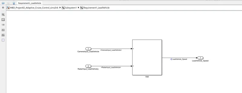
Requirement 1– Lead Vehicle:
- Lead Vehicle is a vehicle which is driving in the road ahead of our drive vehicle. Two input signals (Signal Name: CameraInput_LeadVehicle & RadarInput_LeadVehicle).
- Ideally sensor fusion techniques will be deployed to process & analyze data from camera & radar. For complexity reasons, let’s not adapt to any such algorithms.
- We can simply add both the radar & camera inputs & the corresponding output is read as Speed profile output (Signal Name: LeadVehicle_Speed).
- Speed data of the lead vehicle is critical in implementing the Adaptive Cruise Control algorithm.
Development of MATLAB Simulink model as per requirement 02.
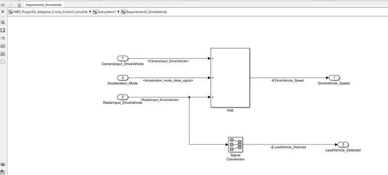
Requirement 2 – Drive Vehicle:
- Drive Vehicle is the vehicle driven by the user & this is the vehicle which has ACC algorithm in it.
- Like the Lead Vehicle, Drive Vehicle algorithm also has 2 input signals (Signal Name: CameraInput_DriveVehicle, RadarInput_DriveVehicle) & one signal coming as an Input to this subsystem (Signal Name: Acceleration_Mode) – three inputs into this requirement in total.
- Like the above requirement, sensor fusion techniques will also be deployed here, for complexity reasons we are ignoring them.
- Two output signals come from this subsystem (Signal Name: DriveVehicle_Speed & LeadVehicle_Detected).
- Signal DriveVehicle_Speed is summation of three input signals mentioned above & LeadVehicle_Detected is renamed from Input Signal RadarInput_DriveVehicle by mere use of Signal Conversion block.
Development of MATLAB Simulink model as per requirement 03.
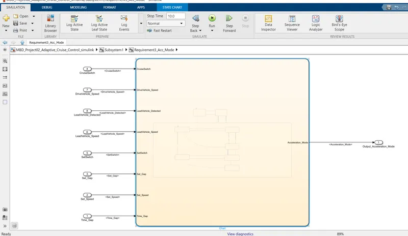
Requirement 3 – Adaptive Cruise Control Algorithm:
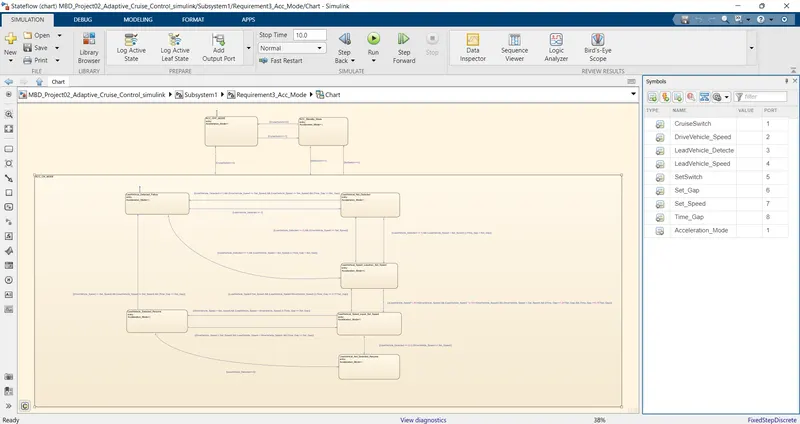
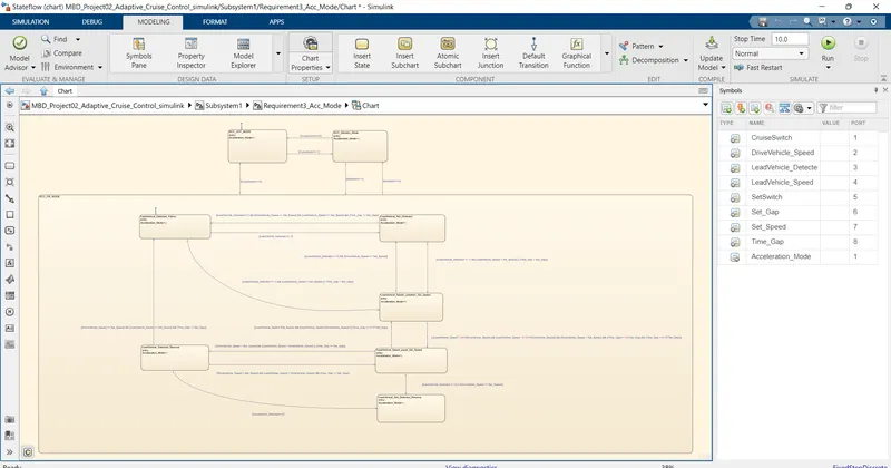
- Adaptive Cruise Control feature has 3 major modes of operation: OFF Mode, STANDBY Mode & ON Mode. This particular requirement has to be implemented as state machine logic in Simulink.
- The input signals to this state machine system are (Signal Name: Time_Gap, Set_Speed, Set_Gap, CruiseSwitch, SetSwitch).
- Also, the output signals (Signal Name: DriveVehicle_Speed & LeadVehicle_Detected) from requirement-2 is fed back as an input signal into this state machine block.
- Additionally, output signal (Signal Name: LeadVehicle_Speed) from requirement-1 is given as an input signal to this state machine block as well.
- Output from this subsystem is a signal (Signal Name: Acceleration_Mode) which governs the vehicular speed of the drive vehicle which automatically adjusts its speed & velocity to match the lead vehicle.
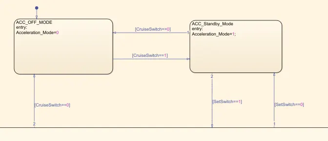
Requirement 3a – ACC OFF MODE state logic:
- This is the default state inside state machine logic. Output signal Acceleration_Mode is at value 0 in this state.
- This state is governed by input signal CruiseSwitch.
- If CruiseSwitch is equal to 1, state ACC STANDBY mode will get activated. If CruiseSwitch is equal to 0, state ACC OFF mode will get activated, from either ACC ON mode or ACC STANDBY mode
Requirement 3b – ACC STANDBY MODE state logic:
- This is the second activated state inside state machine logic. Output signal Acceleration_Mode is at value 1 in this state.
- This state is governed by both input signals CruiseSwitch & SetSwitch.
- If CruiseSwitch is equal to 1, state ACC STANDBY mode will get activated. If CruiseSwitch is equal to 0, state ACC OFF mode will get activated, from either ACC ON mode or ACC STANDBY mode
- If SetSwitch is equal to 1, state ACC ON mode will get activated. If SetSwitch is equal to 0, state ACC STANDBY mode will get activated.
Requirement 3c – ACC ON MODE state logic:
This state will be activated when input signal SetSwitch is equal to 1. There are 6 sub states to this state logic: They are:
- LeadVehicle_Detected_Follow (Default)
- LeadVehicle_Not_Detected
- LeadVehicle_Detected_Resume
- LeadVehicle_Not_Detected_Resume
- LeadVehicle_Speed_lessthan_Set_Speed
- LeadVehicle_Speed_equal_Set_Speed
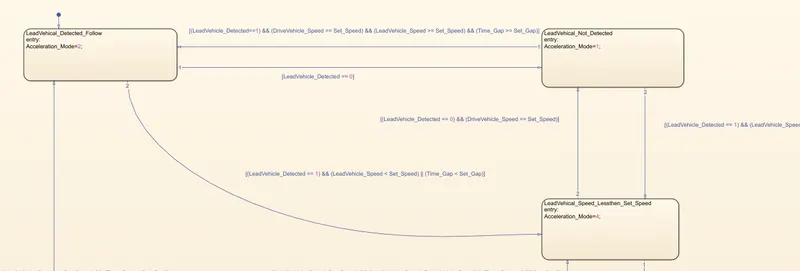
Requirement 3c (i) – LeadVehicle_Detected_Follow (ACC ON MODE):
- This is the default sub state inside ACC ON MODE state. Output signal Acceleration_Mode is equal to 2.
- Condition to transit from LeadVehicle_Detected_Follow to LeadVehicle_Not_Detected; Input signal condition LeadVehicle_Detected == 0.
- Condition to transit from LeadVehicle_Detected_Follow to LeadVehicle_Speed_lessthan_Set_Speed; Input Signals condition (LeadVehicle_Detected == 1) && (LeadVehicle_Speed < Set_Speed) || (Time_Gap < Set_Gap).
Requirement 3c (ii) – LeadVehicle_Not_Detected (ACC ON MODE):
- Output signal Acceleration_Mode is equal to 1.
- Condition to transit from LeadVehicle_Not_Detected to LeadVehicle_Detected_Follow; Input signals condition [(LeadVehicle_Detected==1) && (DriveVehicle_Speed == Set_Speed) && (LeadVehicle_Speed >= Set_Speed) && (Time_Gap >= Set_Gap)]
- Condition to transit from LeadVehicle_Not_Detected to LeadVehicle_Speed_lessthan_Set_Speed; Input signals condition [(LeadVehicle_Detected == 1) && (LeadVehicle_Speed < Set_Speed) || (Time_Gap < Set_Gap)]
Requirement 3c (iii) – LeadVehicle_Detected_Resume (ACC ON MODE):
- Output signal Acceleration_Mode is equal to 3.
- Condition to transit from LeadVehicle_Detected_Resume to LeadVehicle_Detected_Follow; Input signals condition [(DriveVehicle_Speed == Set_Speed) && (LeadVehicle_Speed >= Set_Speed) && (Time_Gap >= Set_Gap)]
- Condition to transit from LeadVehicle_Detected_Resume to LeadVehicle_Not_Detected_Resume; Input signal condition LeadVehicle_Detected==0.
- Condition to transit from LeadVehicle_Detected_Resume to LeadVehicle_Speed_equal_Set_Speed; Input Signal condition [(DriveVehicle_Speed < Set_Speed) && (LeadVehicle_Speed > DriveVehicle_Speed) && (Time_Gap >= Set_Gap)]
Requirement 3c (iv) - LeadVehicle_Not_Detected_Resume (ACC ON MODE):
- Output signal Acceleration_Mode is equal to 1.
Requirement 3c (v) - LeadVehicle_Speed_lessthan_Set_Speed (ACC ON MODE):
- Output signal Acceleration_Mode is equal to 4.
- Condition to transit from LeadVehicle_Speed_lessthan_Set_Speed to LeadVehicle_Not_Detected; Input signal condition [(LeadVehicle_Detected == 0) && (DriveVehicle_Speed == Set_Speed)]
- Condition to transit from LeadVehicle_Speed_lessthan_Set_Speed to LeadVehicle_Speed_equal_Set_Speed; Input signals condition [((LeadVehicle_Speed*1.25>=DriveVehicle_Speed) && (LeadVehicle_Speed * 0.75<=DriveVehicle_Speed)) && (DriveVehicle_Speed < Set_Speed) && ((Time_Gap<=1.25*Set_Gap) && (Time_Gap >=0.75*Set_Gap))]
Requirement 3c (vi) - LeadVehicle_Speed_equal_Set_Speed (ACC ON MODE):
- Output signal Acceleration_Mode is equal to 5.
- Condition to transit from LeadVehicle_Speed_equal_Set_Speed to LeadVehicle_Not_Detected_Resume; Input signal conditions is [(LeadVehicle_Detected == 0) || (DriveVehicle_Speed <= Set_Speed)]
- Condition to transit from LeadVehicle_Speed_equal_Set_Speed to LeadVehicle_Detected_Resume; Input signal conditions [(DriveVehicle_Speed < Set_Speed) && (LeadVehicle_Speed > DriveVehicle_Speed) || (Time_Gap >= Set_Gap)]
- Condition to transit from LeadVehicle_Speed_equal_Set_Speed to LeadVehicle_Speed_lessthan_Set_Speed; Input signals conditions
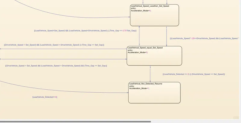
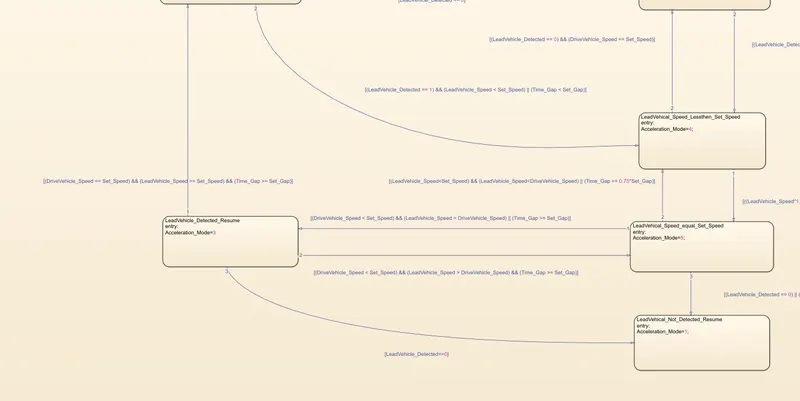
For above requirement according full flow chart is design like below.
Data Dictionary creation according to given signal & Calibration Data.
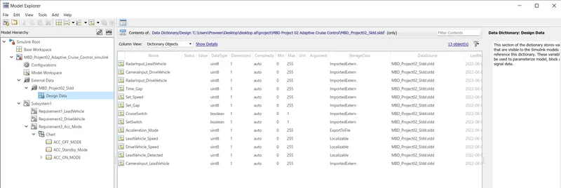
for Chart define the values
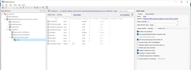
For Chart properties Goto Modelling in that Tab go to the chart Properties.
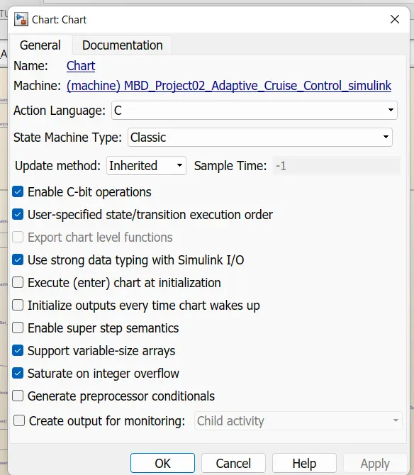
open below page set according recommded setteing.
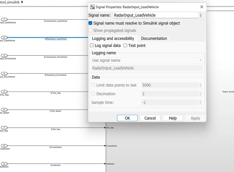
then Select Signal name must resolve to Simulink Signal object.
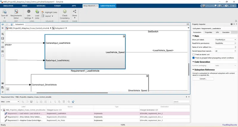
Requirement Tagging & Traceability:-
First open the which document required which attached to model.Select and open the subsystem.
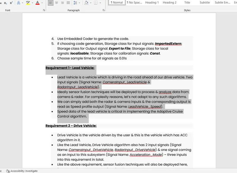
then goto Subsystem and right click and go in Requirements openand then according required document select like Link to Selection in Word.
after that again click Right click where show Selected requirement.
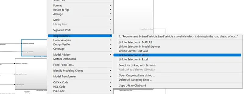
then Subsystem goes into yellow colour.
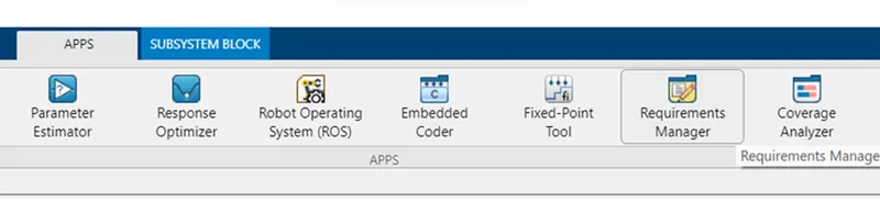
Requirement Trackability go to the Apps Tab and open Requirements Manager.
After opening then below page is open where show Requirement trace.
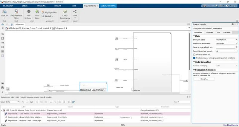
In Subsystem Link appear like below
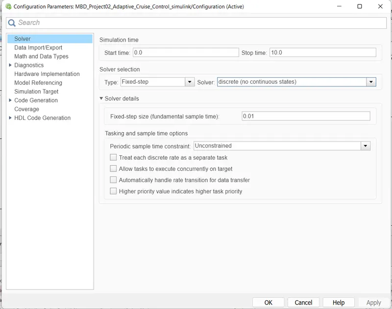
Configuration Parameter and Select Simulation Time.Solver Selection as Fixed Step and Solver as discrete signal.
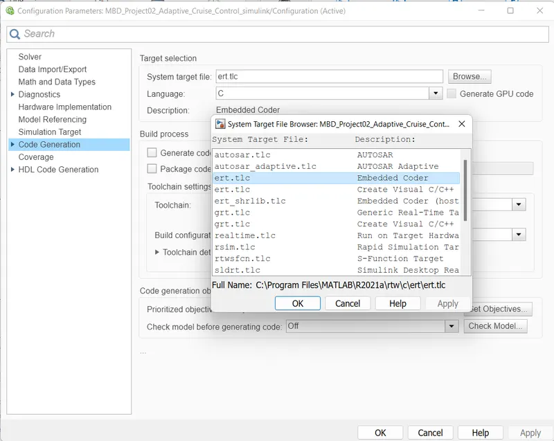
then goto Code Genration where System target file Select as ert.tlc.
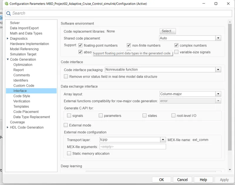
In Configuration Parameters: enable “Support Floating Numbers” under Code Generation settings.
Code Generation:-
Right click on Main Subsystem
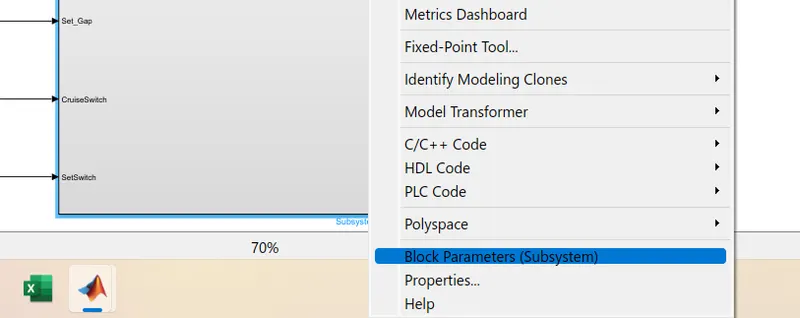
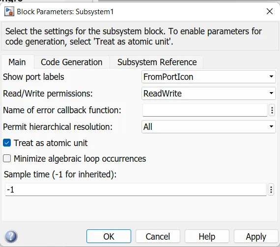
Select as Treat as atomic unit.
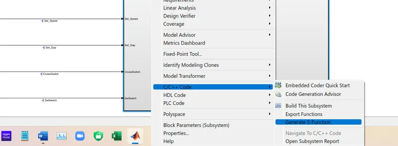
After that Right click the subsystem and go in c/c++ Code in this go for thje Generate S-Function.
In this select the Create SIL block and then Build select.
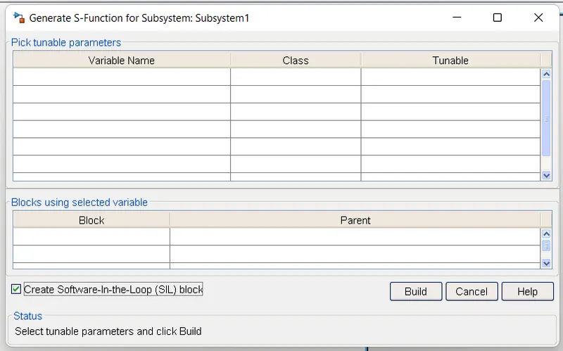
then proccess is completed the below page is open.
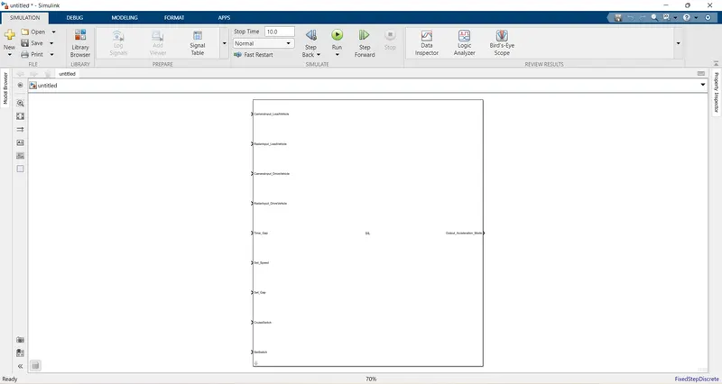
For Code genration go C code.

After that code will be generated avilable in view code.
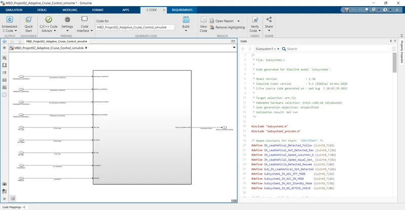
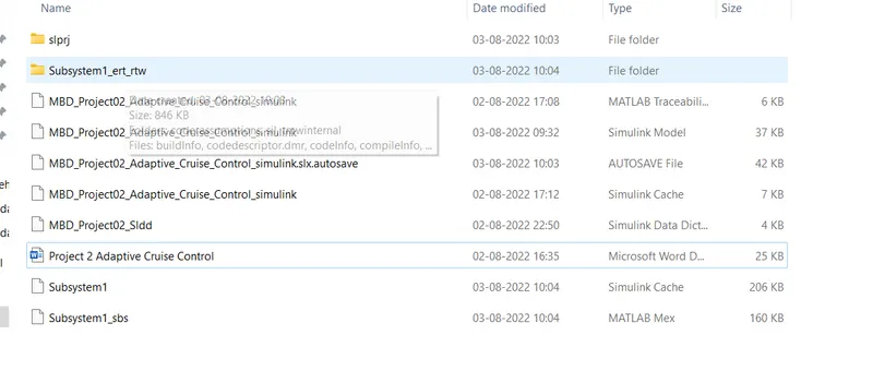
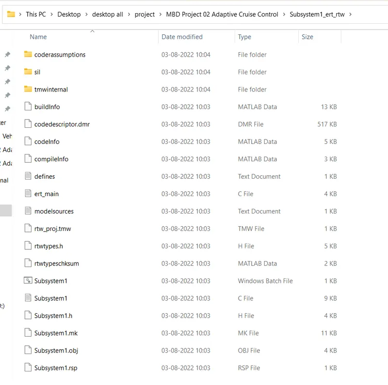
File of c code store in Same folder.
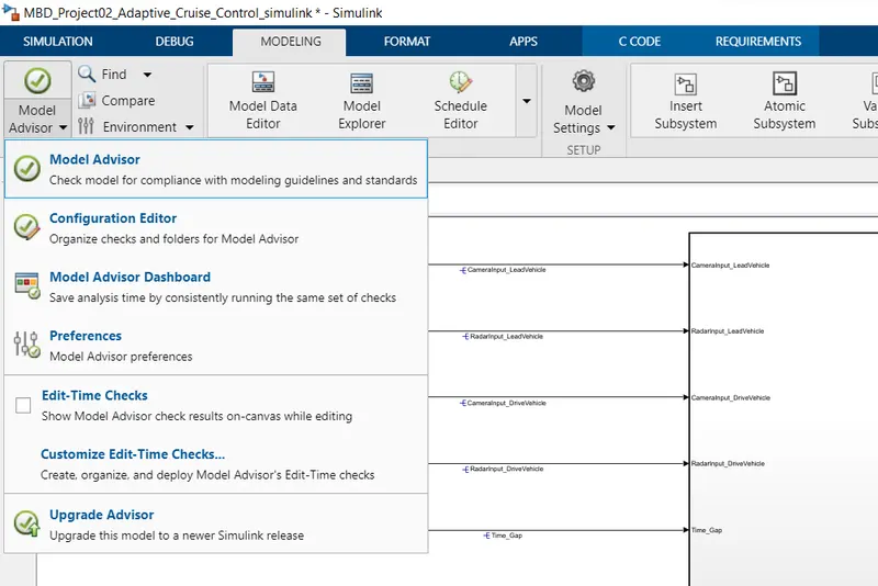
Model Advisor check:- For Model Advisor test goto Modelling Tab then goto the Model Advisor.
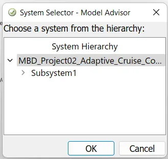
After that Select System Hierarchy.
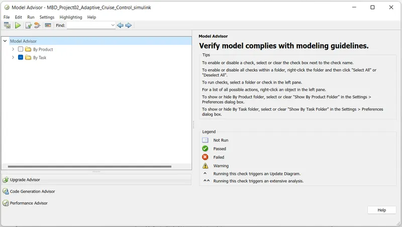
Below page is open then goto By Task.
Select the MAAB & JMAAB test select.
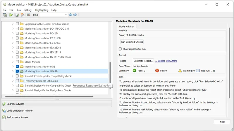
After selection Run Selected checks.
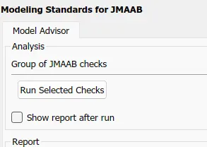
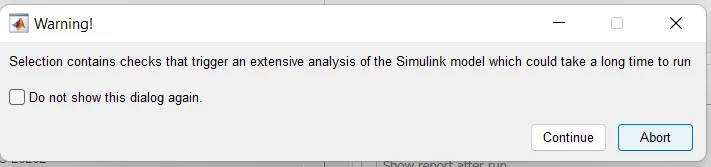
Then Continue
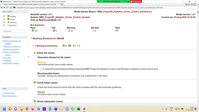
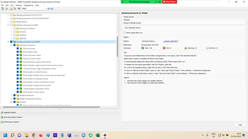
After completing the process below page is open which show the result.
For Genrate Report Select Generate Report or blue line link open.
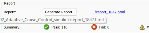
After this page open which provide below information.
HTML report is opened. By use of print option save the report.