Week -2
Question no. 1) Make a Simulink model of Doorbell using solenoid block with the following details.
In the above arrangement, when the switch is closed the electromagnet receives electrical power from the battery and pull the metal arm to hit the bell producing sound.
Create a situation where the switch is closed for 2 sec and the released. Observed the physical movment of the Plunger.
Assuming remainning parameters.
Solution:-
AIM:- Create a Simulink model of Doorbell using solenoid block with the following details.
a. when the switch is closed the electromagnet receives electrical power from the battery and pull the metal arm to hit the bell producing sound.
b.where the switch is closed for 2 sec and the released. Observed the physical movment of the Plunger.
Theory:- In this Simulatiom model solenoid block use. in elecrical part input supply provide then mechnical part of the solenoin move. Ideal translation motion sensor sense Velocity and position of the mechnical part.
Doorbell using solenoid block model:-
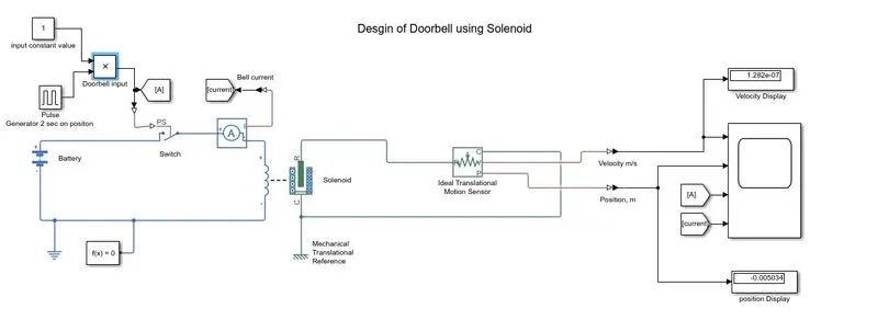
Simulink Block used:-
1. Constant :- constant 1 value is used for swithich on input value.
2. Pulse Generator:- we need 2 sec on positon so pulse genrator block is used.
3. Product block:- The Product block outputs the result of multiplying two inputs.
4. Battery block:- The Battery block represents a simple battery model.In this model 12 voltage and 2 ohm internal resistance is used .
5. Solenoid block:- The Solenoid block represents the electrical characteristics and generated force for the solenoid.when voltage applied.
6. Translational Motion Sensor:- The Ideal Translational Motion Sensor block represents a device that converts an across variable measured between two mechanical translational nodes into a control signal proportional to velocity or position.
7. Goto block:- The Goto block passes its input to its corresponding From blocks.
8. Current Sensor block:- The Current Sensor block represents an ideal current sensor, that is, a device that converts current measured in any electrical branch into a physical signal proportional to the current.
9. Solver Configuration block:- Each physical network represented by a connected Simscape block diagram requires solver settings information for simulation. The Solver Configuration block specifies the solver parameters that your model needs before you can begin simulation.
10. Mechanical Translational Reference block:- The Mechanical Translational Reference block represents a reference point, or frame, for all mechanical translational ports. All translational ports that are rigidly clamped to the frame (ground) must be connected to a Mechanical Translational Reference block.
11. Display:- The Display block shows the value of the input data.
12. Scope:- Time Scope block display time domain signals.
13. PS-Simulink Converter:- The PS-Simulink Converter block converts a physical signal into a Simulink output signal. Use this block to connect outputs of a Physical Network diagram to Simulink scopes or other Simulink blocks.
14. Electrical Reference block:- The Electrical Reference block represents an electrical ground. Electrical conserving ports of all the blocks that are directly connected to ground must be connected to an Electrical Reference block. A model with electrical elements must contain at least one Electrical Reference block.
Input Signal for switch:-
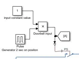
In above block digram show 1 constant value is provided as an input. Pulse Generator use for 2 sec on condition and after that of the signal. Both Constant and pulse generator value's product value is ''A'' which is used to operate switch.
Remark- At those condition where a person hold the bell switch continous on so input of solenoid is continous. for according to question in input signal required switch is closed for 2 sec and the released so that solution pulse generator block use for 2 sec on postion, next 2 sec off positon. in next 2 sec position bell recahed its previous position. and constant 1 value denote the person hold the switch continous on.
Electrical Connection:-
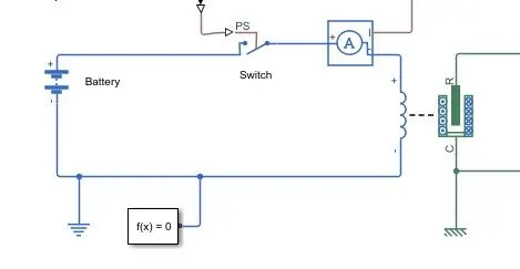
In above blue line ckt a battery 12 volt is connected with switch and solenoid.electrical reference block represents an electrical ground.Each physical network represented by a connected Simscape block diagram requires solver settings information for simulation.The Current Sensor block measured the value of current flow in CKT.
When the signal provide in switch input after that Switch get closed. Current will flow and a voltage will applied in solenoid terminal. After applied voltage at solenoid its working according its characteriscs.
Mechanical Connection:-
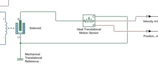
In above block Diagram shows mechanical connection of Solenoid which is connected with Ideal Translation motion Sensor for sense the value of Velocity and Position of solenoid. Mechanical Translational Reference block represents a reference point, or frame, for all mechanical translational ports.
Output Measuring Connection:-
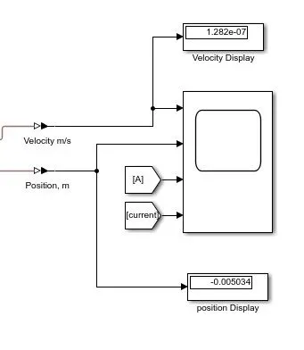
In the above connection Display block and scope block are used for the measure resultant value.
Result:-
After Run the Simulation for 10sec the result in display.
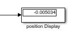
Position Display shows value -0.005034 m after 10 sec.
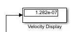
Velocity Display show value 1.282e-07 m/s after 10 sec.
Scope output
After Run the Simulation for 10sec the result in Scope.
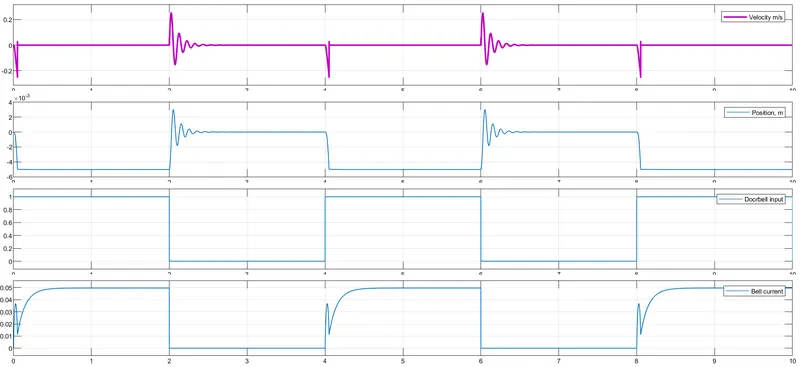
At 0 sec to 4 sec
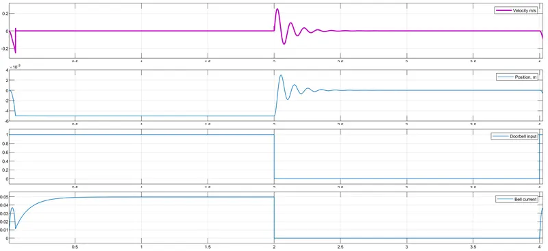
When constant 1 value is applied after that resultant in starting 2 sec doorbell is on and after that doorbell goes to off position for 2 sec.
Observation In above scope result analysis are
Velocity- In Velocity graph value analysis
- 0 to 0.049 sec time its velocity shift from 0 to -233.436 mm/s.
- 0.049 to 0.062 sec time its velocity shift from -233.436 to -147.148 um/s.
- 0.068 to 1.963 sec time its velocity is almost constant.
- 1.988 to 2.633 sec time its velocity position vibration like sinusoidal with decreasing amplitude .
- 2.633 to 4 sec time its velocity position is almost constant.
Position- In Position graph value analysis
- 0 to 0.062 sec time its Position shift from 0 to -5.002mm.
- 0.062 to 1.98 sec time its Position is almost constant.
- 1.98 to 2.63 sec time its position vibration like sinusoidal with decreasing amplitude .
- 2.633 to 4 sec time its position is almost constant.
Doorbell input- In Doorbell input graph value analysis
- 0 to 2 sec time its amplitude is constant 1.
- 2 to 4 sec time its amplitude is constant 0.
Bell current- In Doorbell current graph value analysis
- 0 to 0.024 sec time current value is 36.564 mA.
- 0.024 to 0.055 sec time current value is 13 mA.
- 0.055 to 0.579 sec time current value is 49.33 mA.
- 0.579 to 1.98 sec time current value is 49.58 mA almost constant.
- 2 sec to 4 sec time current value is 0.
Conclusion:- after run the simulation the final conclusion is
a. when the switch is closed the electromagnet receives electrical power from the battery current value is show electrical ckt current consumption and pull the metal arm to hit the bell producing sound show in graph.
b.where the switch is closed for 2 sec and the released. The physical movment of the Plunger clearly showing in result section and graph also indicate the position.
Question no. 2) Use a thermistor to sense the temperature of a heater and turn on or off the fan as perthe below condition.
a. Temperature source;- 20°C from o to 10 seconds, 27°C from 10 to 30second. 23°C from 30 to 50 seconds
b. Fan condition- ON if the temperature above 25°C, OFF otherwise.
Solution:-
AIM:- Create a Simulink model of use a thermistor to sense the temperature of a heater and turn on or off the fan as perthe below condition.
a. Temperature source;- 20°C from o to 10 seconds, 27°C from 10 to 30 seconds. 23°C from 30 to 50 seconds
b. Fan condition- ON if the temperature above 25°C, OFF otherwise.
Thermistor block model:-
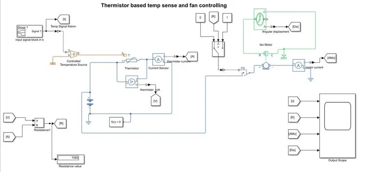
Simulink Block used:-
1. Signal Builder :- In this block provide input signal to simulink model accordingly question
Signal Builder Graph Image 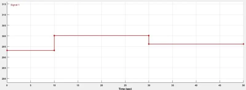 In above grapth of input signal which is provided signal value 0 to 10 sec 20°C after that 10 to 30 sec its provide 27°C value after 30 to 50 sec its provide 23°C value. above all value of °C value first conver into Kelvin for simulation.
2. Controlled Temperature Source:- The Controlled Temperature Source block represents an ideal source of thermal energy that is powerful enough to maintain specified temperature difference across the source regardless of the heat flow consumed by the system.
3. Thermistor block :-
The Thermistor block represents an NTC thermistor using the B-parameter equation. The resistance at temperature T is
R=R0eB(1/T−1/T0)
where:
-
R0 is the nominal resistance at the reference temperature T0.
-
B is the characteristic temperature constant.
4. DC motor:- In the above model Brushed DC Motors is used.
5. Current Sensor block:- The Current Sensor block represents an ideal current sensor, that is, a device that converts current measured in any electrical branch into a physical signal proportional to the current.
6. Voltage Sensor block:- The Voltage Sensor block represents an ideal voltage sensor, that is, a device that converts voltage measured between two points of an electrical circuit into a physical signal proportional to the voltage.
7. Ideal Rotational Motion Sensor block:- The Ideal Rotational Motion Sensor block represents an ideal mechanical rotational motion sensor, that is, a device that converts an across variable measured between two mechanical rotational nodes into a control signal proportional to angular velocity or angle. You can specify the initial angular position (offset) as a block parameter.
8. Scope:- Time Scope block display time domain signals.
9. Battery block:- The Battery block represents a simple battery model.In this model 12 voltage and 2 ohm internal resistance is used .
Working procedure:-
- First with the help of Signal Builder block signal provide according question to controlled temperature source.All value in of input of temperature source in kelvin.
- In next step according to signal find out the value of resistance of thermister. in this block use NTC thermistor used.
- In next step resistor value use for conditional switch which is provide signal to fan switch on or off.
- Acoording to question fan must be on when temperature is above 25°C for this situation first find the value of thermistor resistance at 25°C. and put value at conditional switch.
- when temp is above 25°C fan on through fan switch.
- fan cureent sense for the fan on condition.
Result:-
OUTPUT of scope:- after 50 sec simulation run output of scope is below
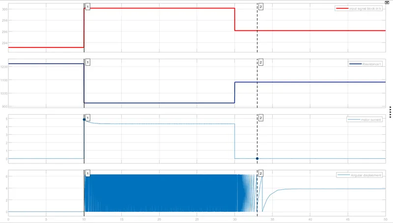
Observation:- Below observation after 50 sec simulation run throught scope
Thermistor Resistance -
- From 0 to 10 sec thermistor resistance value is 1222 ohm.
- From 10 to 30 sec thermistor resistance value is 924.8 ohm.
- From 30 to 50 sec thermistor resistance value is 1083 ohm.
Motor Current -
- From 0 to 10 sec fan motor current value is almost 0 A.
- From 10 to 12 sec fan motor current value is almost 4.85A to 4.37A.
- From 12 to 30 sec fan motor current value is almost constant at 4.37A.
- From 30 to 50 sec fan motor current value is almost 0 A.
Angular Displacement -
- From 0 to 10 sec angular displacement is constant at 0 rad.
- From 10 to 33 sec angular displacement is continous.
- From 30 to 50 sec angular displacement is constant at 3.85 rad.
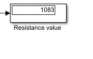
DISPLAY result:- after run of 50 sec of simulation at 50sec resistance value is 1083 ohm.
Conclusion:- after run the simulation the final conclusion is
a. Temperature source provide 20°C from o to 10 seconds, 27°C from 10 to 30second. 23°C from 30 to 50 seconds according to this resistance value of thermistor is changred.
b. Fan condition- ON if the temperature above 25°C, OFF otherwise. according to condtion fan working. 30 to 33 sec time taken by fan for take constant position.