Project 1 (Mini Project on Vehicle Direction Detection
Aim of Project:- Vehical Direction Indication help the driver for he is goes in correct way. System provide information with the help of Camera Signal,SteeringWheel yawDegree and some other signal which provide a error less output.
In the project steering wheel input as yaw rate is comparing with 3 angular value limit of Right,Left and Straight angle.Which provide Turn Status Signal of vehicle which provide information about vehical direction.After that this signal provide next stage where the signal compared with Angular limit of Right,Left & Straight Angle.if true then compare with the Camera Signal with the help of logical operator block the provide Signal to Vehical Direction Indicator.
In the project Yaw degree ,Right & Left Angular limits & Straight Drive Angle ,Right,Left & Straight Road Sign, Camera signalwith help of them using Provided Requiement 01 & Requirement 02 condition statisfy then provide a meaning full signal out of Vehical Direction Indicator.
Simulink Model:- For this Creating Subsystem block
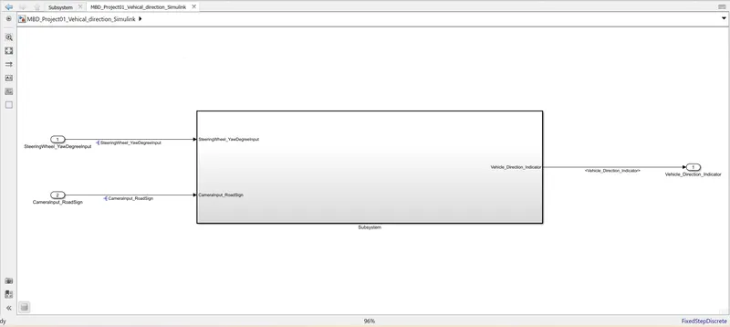
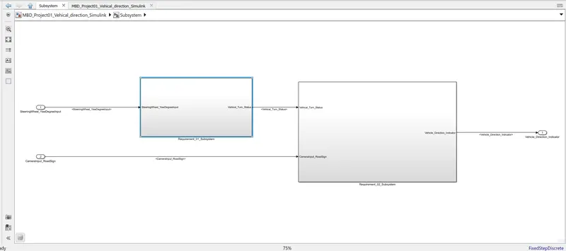
In main Subsystem create 2 Subsystem name is Requirement_01_Subsystem and Requirement_02_Subsystem.
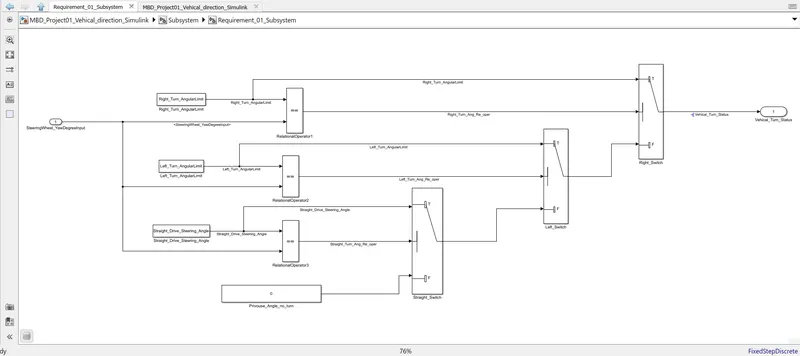
Development of MATLAB Simulink model as per requirement 01.
Development of MATLAB Simulink model as per requirement 02.
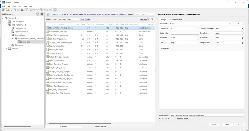
Data Dictionary creation according to given signal & Calibration Data.
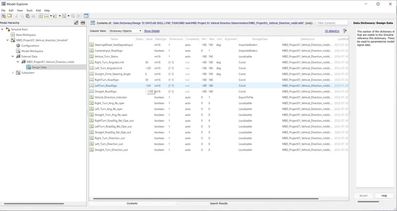
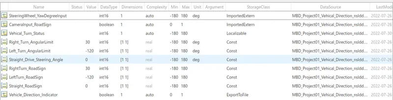
Below data added in Simulink Data Dictionary which is given in question.
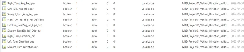
Below data added in Simulink Data Dictionary which is not given in question. Genrate for local Signals.
Sample time of Signal set as 0.01s.
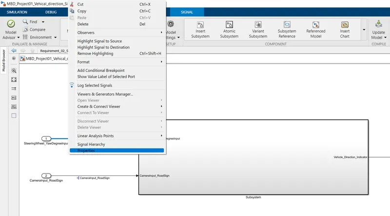
After Creating the SLDD Signal Link with Sldd for this Right Click on signal and goto Properties.
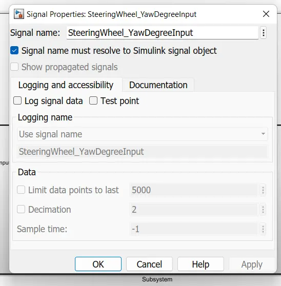
then Select Signal name must resolve to Simulink Signal object.
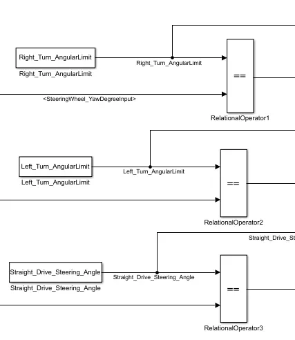
For propagation of line use'<>' then look like below.

Requirement - 1:
This is compared against 3 angular values, one each for left turn, right turn & straight drive (Calibration Values: Right_Turn_AngularLimit, Left_Turn_AngularLimit, Straight_Drive_Steering_Angle) to say which specific direction the steering wheel is turning towards. According to this requirement Relational block is used for the Compared SteeringWheel_YawDegreeInput with Righ, Left,Straight Turn Angular limt with the help od individual Relational block.
In this Simulation model
1) Right_Turn_AngularLimit value is equal to SteeringWheel_YawDegreeInput its RelationalOperator1 provide true 1 boolean value otherwise when not equal its provide false 0 boolean value.
Output is Right_Turn_Angular_Re_oper, which is connecting to Right_Switch.
2)Left_Turn_AngularLimit is equal to SteeringWheel_YawDegreeInput its RelationalOperator1 provide true 1 boolean value otherwise when not equal its provide false 0 boolean value.
Output is Left_Turn_Angular_Re_oper, which is connecting to Left_Switch.
3)Straight_Drive_Steering_Angle is equal to SteeringWheel_YawDegreeInput its RelationalOperator1 provide true 1 boolean value otherwise when not equal its provide false 0 boolean value.
Output is Straight_Turn_Angular_Re_oper, which is connecting to Straight_Switch.
- Use switch blocks to compare & develop this requirement. Keep this requirement in a subsystem & output of this requirement is a local signal (Signal Name: Vehicle_Turn_Status).After the signal came after the relation block then its goes to Switch for provide the first signal pass through output. which is satisfy the condition according Out is goes to Vehical_Turn_Status.
In below simulation model
1) Right_Turn_Angular_Re_oper, which is connecting to Right_Switch port 2 for condition checking and the switch 1st port connected to Right_Turn_AngularLimit. when the Right_Turn_Angular_Re_oper signal value is 1 the switch passes the first signal as the value of Right_Turn_AngularLimit. otherwise its provide the 3 port value which is connected to the Left Switch output.and Right_Switch output is connected with the Outprt of Vehical_Turn_Status which is a localizable signal.
2) Left_Turn_Angular_Re_oper, which is connecting to Left_Switch port 2 for condition checking and the switch 1st port connected to Left_Turn_AngularLimit. when the Left_Turn_Angular_Re_oper signal value is 1 the switch passes the first signal as the value of Left_Turn_AngularLimit. otherwise its provide the 3 port value which is connected to the Straight_Switch output.and Left_Switch output is connected with Right_Switch 3rd port.
3) Straight_Drive_Steering_Ang_Re_oper, which is connecting to Straight_Switch port 2 for condition checking and the switch 1st port connected to Straight_Drive_Steering_Angle. when the Right_Turn_Angular_Re_oper signal value is 1 the switch passes the first signal as the value of Straight_Drive_Steering_Angle. otherwise its provide the 3 port value which is connected to constant block which value is "0".and Straight_Switch output is connected to Left switch 3rd port.
th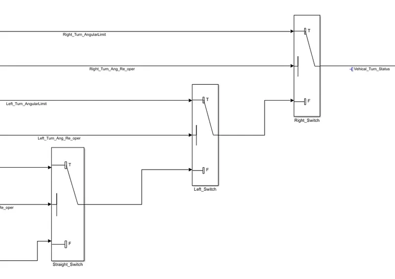
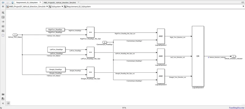
Requirement – 2:
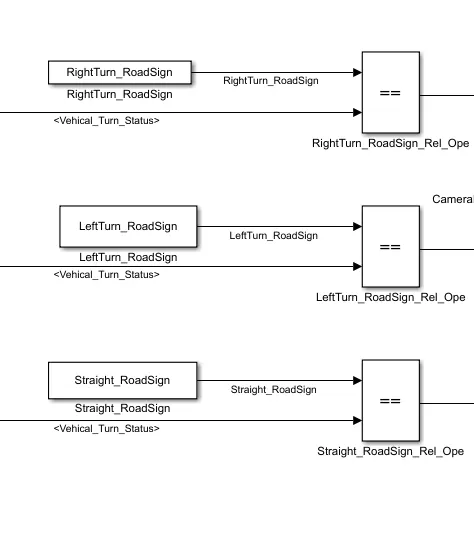
- Signal Vehicle_Turn_Status is compared against calibration values (Calibration Values: RightTurn_RoadSign, LeftTurn_RoadSign, Straight_RoadSign), if each of them is found equal, then each of the three corresponding output is compared against the camera input signal,
In this Simulation model
1) RightTurn_RoadSign value is equal to Vehicle_Turn_Status its RightTurn_RoadSign_Rel_Ope provide true 1 boolean value otherwise when not equal its provide false 0 boolean value.
Output is Right_Turn_Angular_Re_oper, which is connecting to LogicalOperator1 'AND' Gate.
2) LeftTurn_RoadSign value is equal to Vehicle_Turn_Status its LeftTurn_RoadSign_Rel_Ope provide true 1 boolean value otherwise when not equal its provide false 0 boolean value.
Output is Left_Turn_Angular_Re_oper, which is connecting to LogicalOperator2 'AND' Gate.
3) Straight_RoadSign value is equal to Vehicle_Turn_Status its Straight_RoadSign_Rel_Ope provide true 1 boolean value otherwise when not equal its provide false 0 boolean value.
Output is Straight_RoadSign_Angular_Re_oper, which is connecting to LogicalOperator3 'AND' Gate.
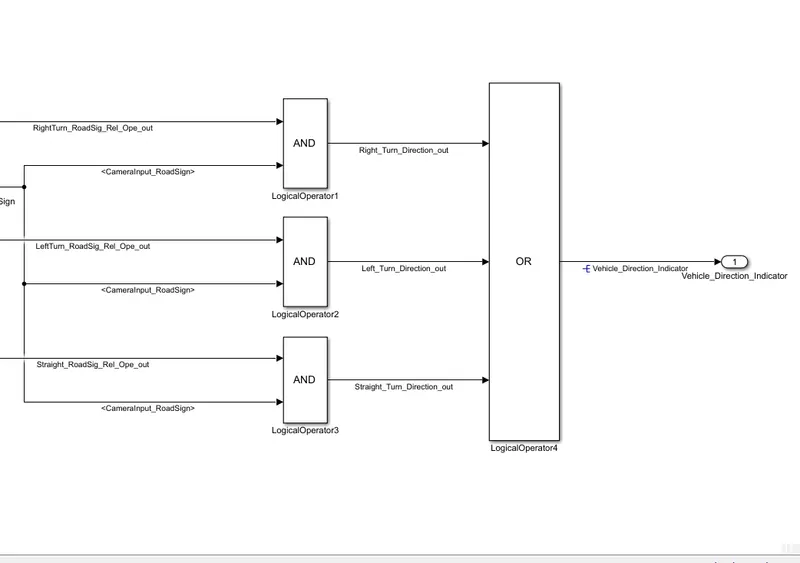
- Using a logical operator block, only one among them is finally given as output signal (Signal Name: Vehicle_Direction_Indicator).
RightTurn_RoadSign_Rel_Ope_out, LeftTurn_RoadSign_Rel_Ope_out & Straight_RoadSign_Rel_Ope_out campare with CameraInput_RoadSign. any one of them value is matched with CameraInput_Roadsignal value so the provide signal to "OR" LogicalOperator in this Logical Operator all 3 "AND" gate Output is connected with "OR" gate Input and alll value are Boolean.
The Output of the "OR" logical operator is connected with the Vehical_Direction_Indicator outport. This signal is also Select Signal name must resolve to Simulink Signal object.
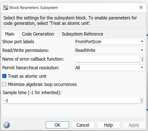
After that Main Subsystem Right click and GOTO the Block Parameters Where Select Treated as Atomic Unit.
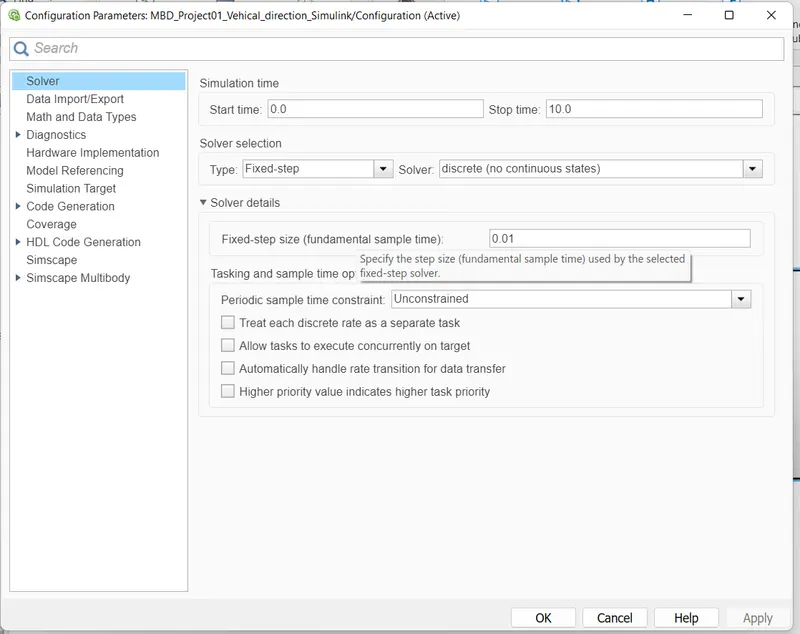
After that goto the Configuration Parameter and Select Simulation Time.Solver Selection as Fixed Step and Solver AS discrete signal.
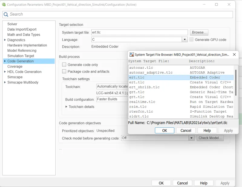
then goto Code Genration where System target file Select as ert.tlc.
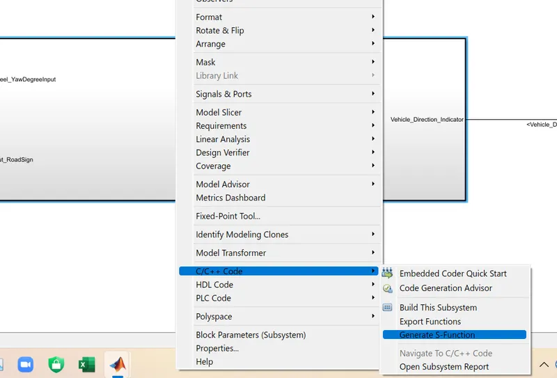
After that Right click the subsystem and go in c/c++ Code in this go for thje Generate S-Function.
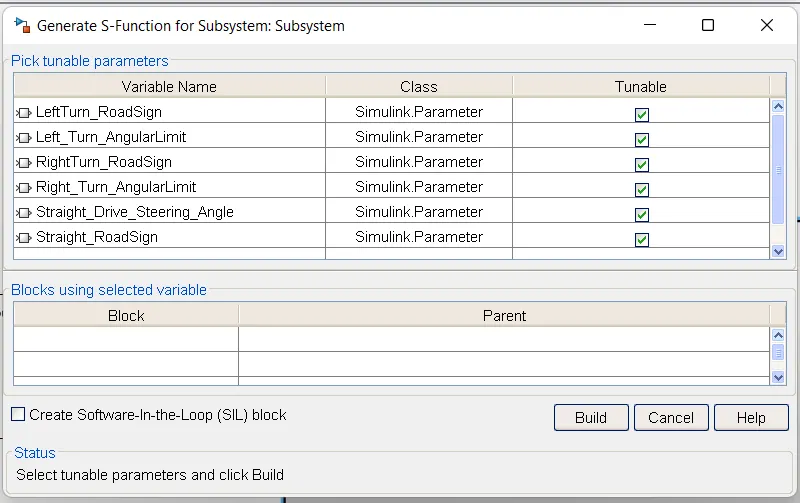
In this select the Create SIL block and then Build selct.
then proceas is completed the below page is open.
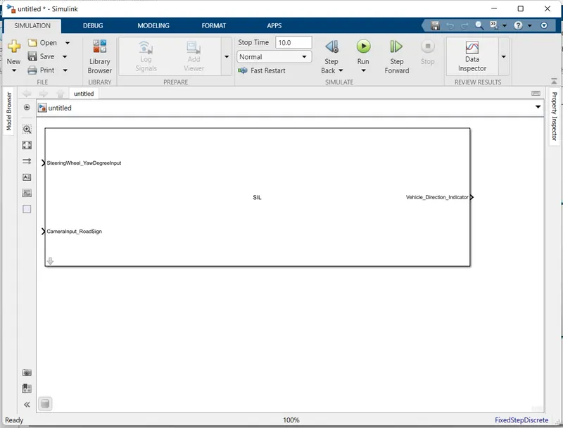
For Code genration go C code.
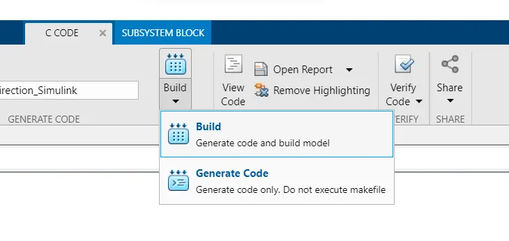
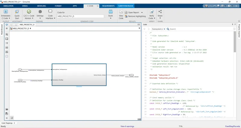
After that code will be generated avilable in view code.
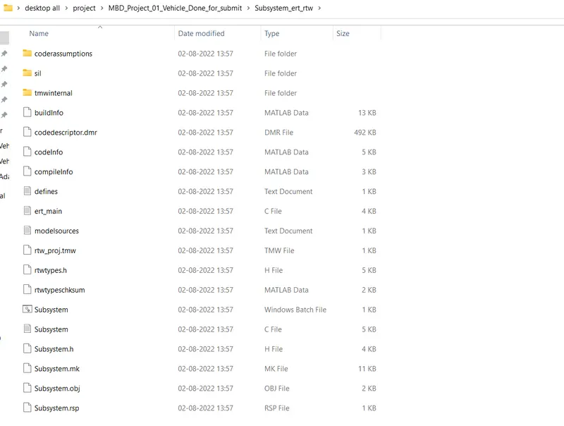
genrated file store in Same folder
Tag the requirements to the simulink model:-
First open the which document required which attached to model.Select and open the subsystem.
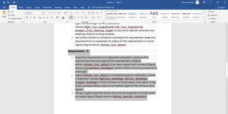
then goto Subsystem and right click and go in Requirements openand then according required document select like Link to Selection in Word.
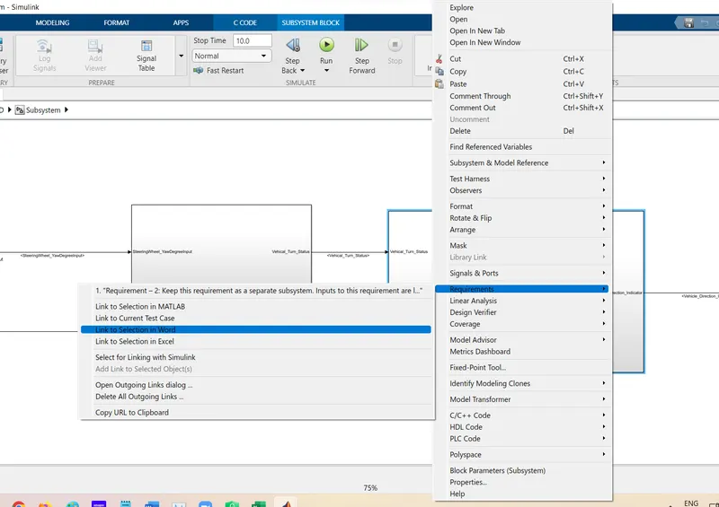
after that again click Right click where show Selected requirement.
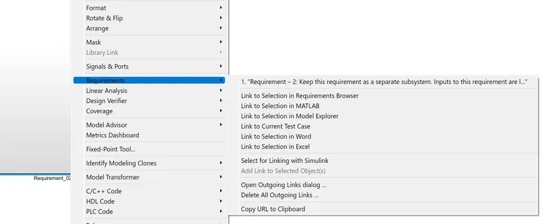
then Subsystem goes into yellow color.
Requirement Tracability goto the Apps Tab and open Requirements Manager.
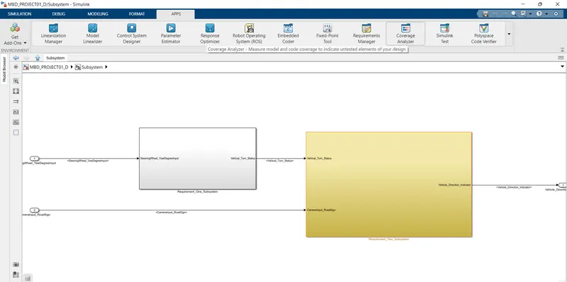
After opening then below page is open where show Requirement trace.
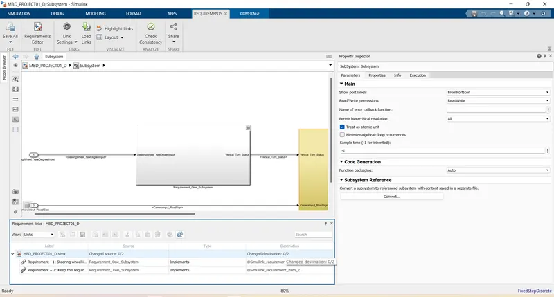
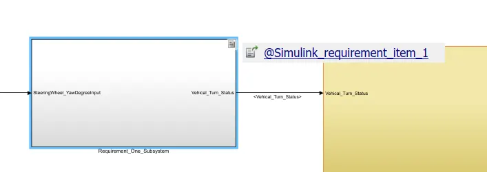
In Subsystem Link appear like below
For Model Advisor test:- Goto Modelling Tab then goto the Model Advisor.
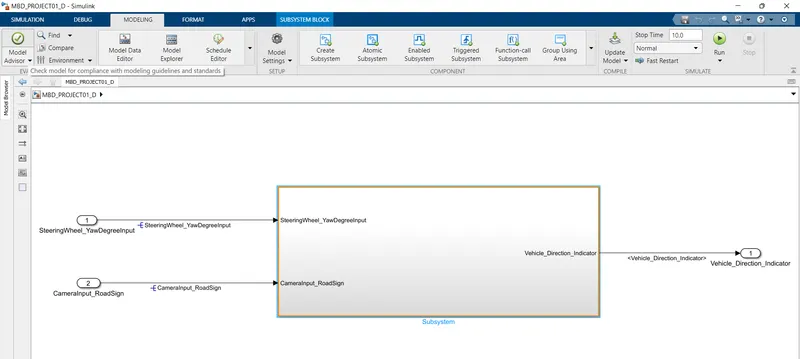
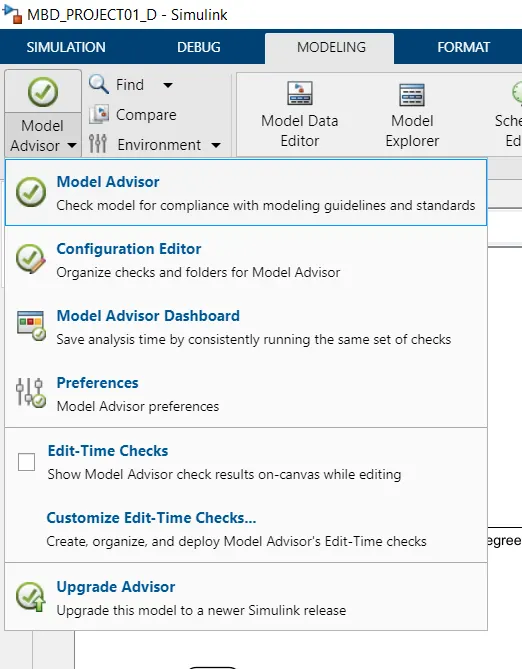
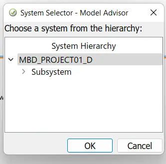
after that Select System Hierarchy.
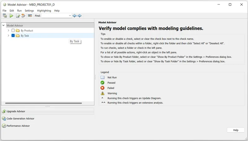
blelow page is open then goto By Task.
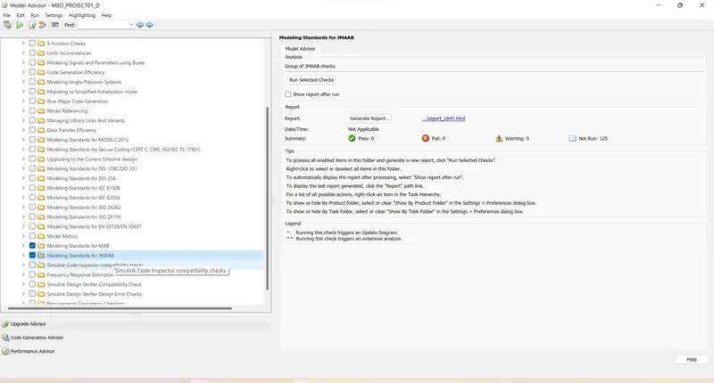
Select the MAAB & JMAAB test select.
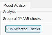
after selection Run Selected checks.
then Continue
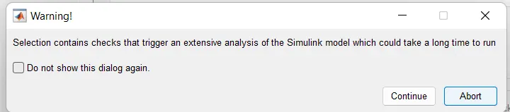
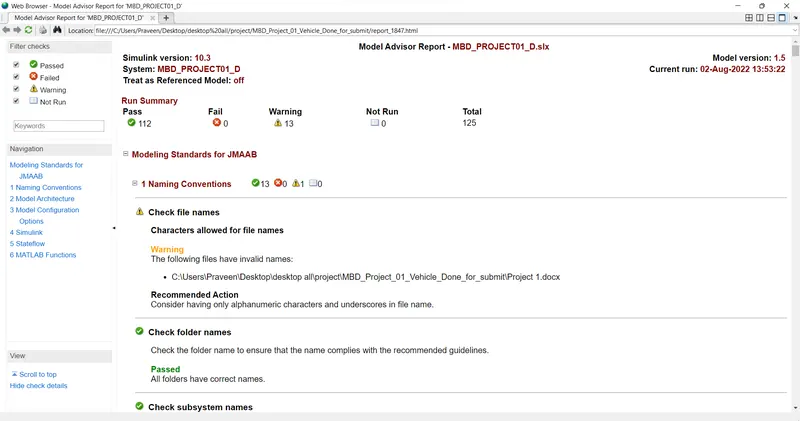
After completing the process below page is open which show the result.
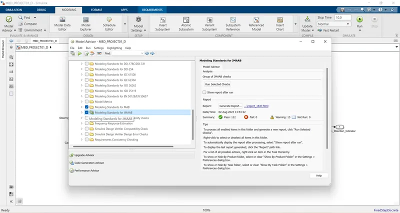
For Genrate Report Select Generate Report.
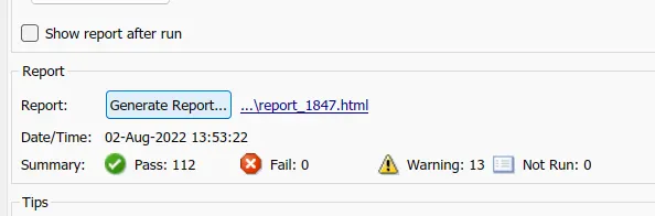
After this page open which provide below information.
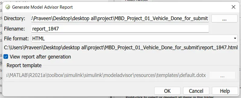
HTML report is opened.