Week-7 Challenge: DC Motor Control
Question no 01:- A. Explain a MATLAB demo model named ‘Speed control of a DC motor using BJT H-bridge’.
B. Comment on the armature current shoot-up from the scope results.
C. Refer to the help section of ‘The Four-Quadrant Chopper DC Drive (DC7) block’. Compare it with the H-bridge model.
Solution:-
Open MATLAB and then goto the help Section And Search model named ‘Speed control of a DC motor using BJT H-bridge’.
Model:-
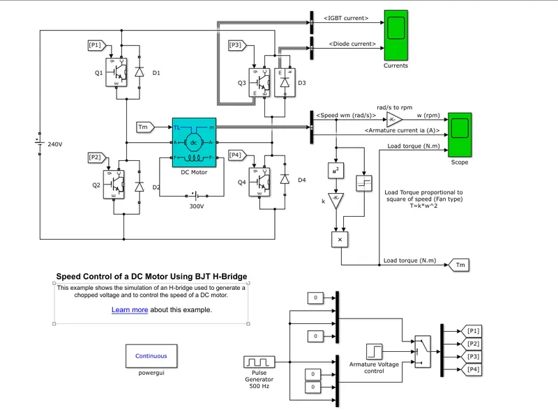
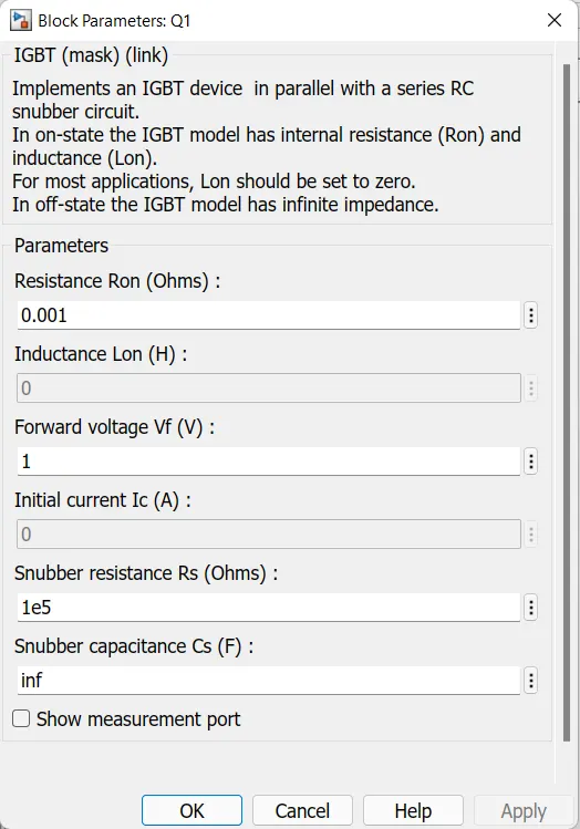
In this model circuit 4 IGBT are used those IGBT parameter are below
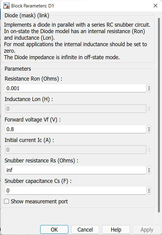
4 qty odf diode is used in parallel with IGBT and diode parameter are
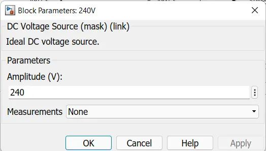
240 volt DC Supply voltage source are use.
DC machine is used those parameter are below.
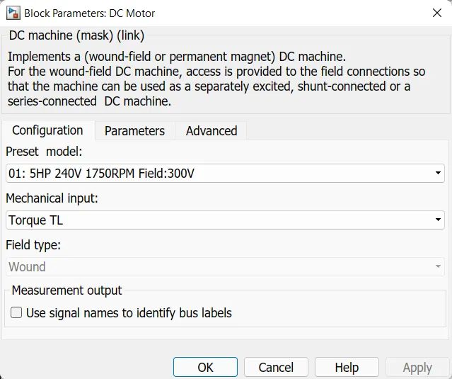
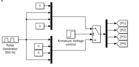
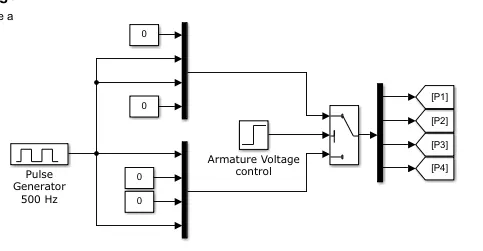
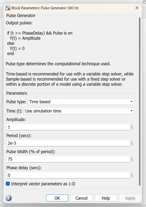
For providing signal to IGBT ckt which provided signal are below where Pulse Generator 500Hz is used.
parameter of pulse generator block are below.

Forward Motor condition
Usually, the H-bridge is used to drive inductive loads, here we drive a DC motor.
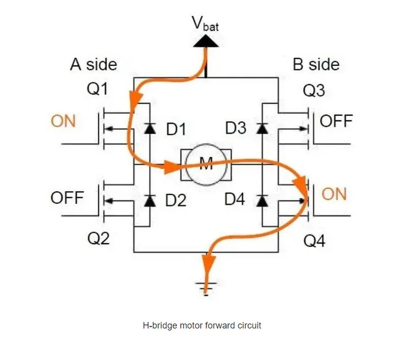
Turn on Q1 and Q4:- In this Current flow through Q1 pass positive voltage and Q2 pass the Negative to the motor as a result of motor rotate forward direction.
Turn off Q2 and Q3:- In this condition both are off or no passing current.
At this point, assuming the motor is forward, this current passes through Q1, M, Q4 in turn, marked in the diagram using the yellow line segment, as shown below
Backward Motor action
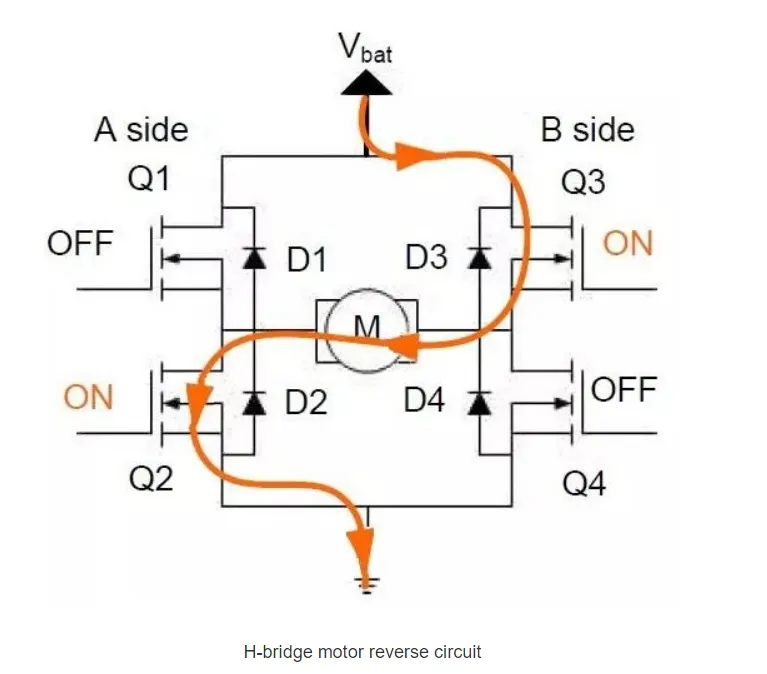
Another state is the motor backward; at this time the state of the four switching components are as follows.
Turning on Q2 and Q3 :- In this Current flow through Q1 pass positive voltage and Q2 pass the Negative to the motor as a result of motor rotate forward direction.
Turning off Q1 and Q4 :- In this condition both are off or no passing current.
At this point the motor reverses (opposite to the case described earlier), which current passes through Q2, M, and Q3 in turn, marked in the diagram using yellow lines, as shown in the figure below.
Speed regulation
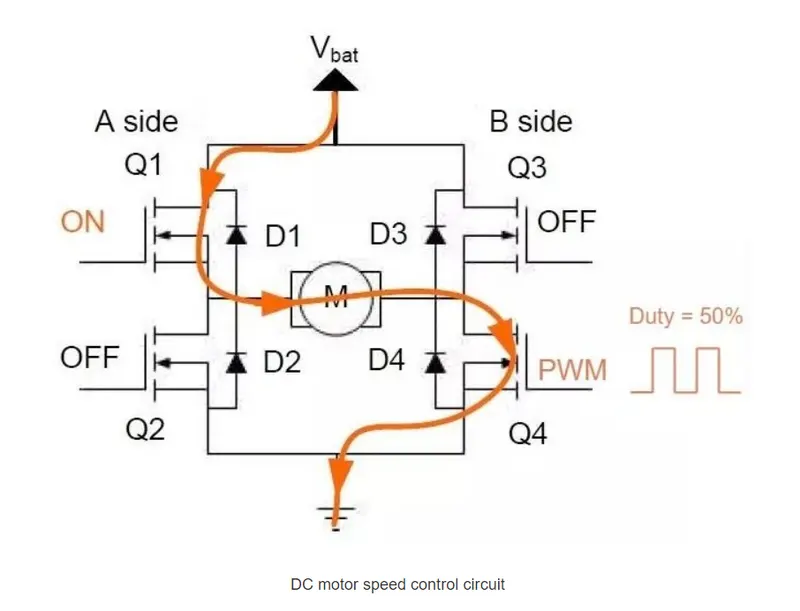
If the DC motor is to be speed regulated, one of the options is.
Turning off Q2, Q3.
Turning on Q1, giving it a 50% duty cycle PWM waveform on Q4 so that the effect of reducing the speed is achieved, and if the speed needs to be increased, setting the duty cycle of the input PWM to 100%.
As shown below.
Stop state
Here the motor is switched from forward to stop state as an example.
-
In the case of forward, Q1 and Q4 are open.
-
At this time, if Q1 and Q4 are turned off, the DC motor internal can be equivalent to an inductor, that is, inductive load, the current will not change suddenly, then the current will continue to maintain the original direction of flow.
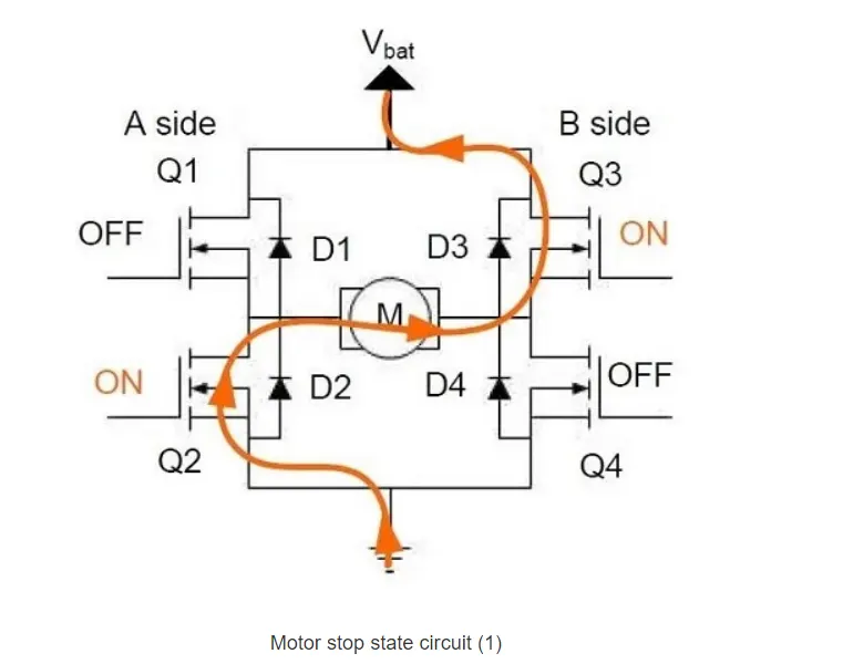
Now, we hope that the current in the motor can be quickly decayed. There are two approaches here.
The first: close Q1 and Q4, when the current will still flow through the reverse continuity diode, then briefly open Q1 and Q3 so as to achieve the purpose of rapid decay of the current.
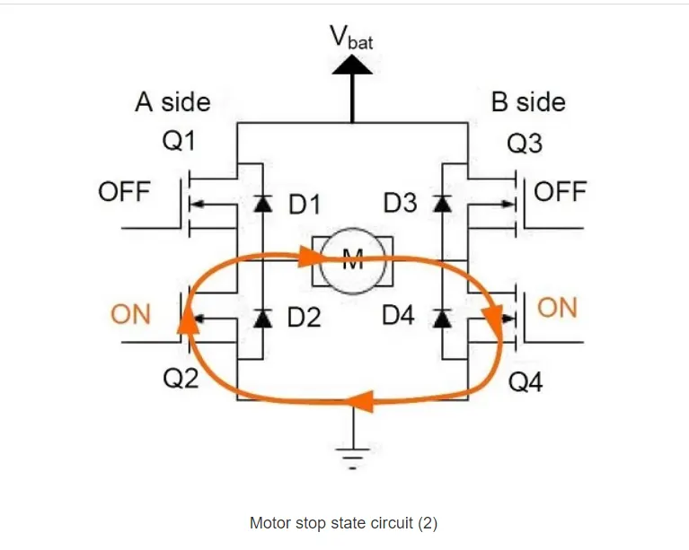
The second: when preparing to stop, turn off Q1 and turn on Q2. At this time, the current does not decay very quickly. The current circulates between Q2, M, and Q4, and the power is consumed by the internal resistance of the MOS-FET.
Result:-
IGBT Current and Diode current.
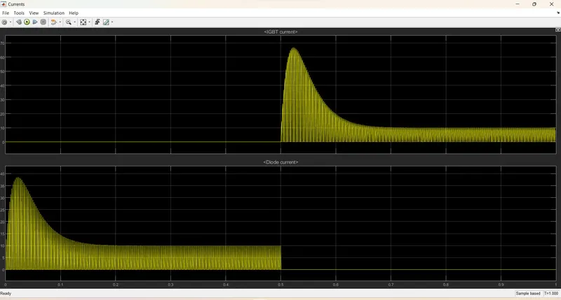
Scope
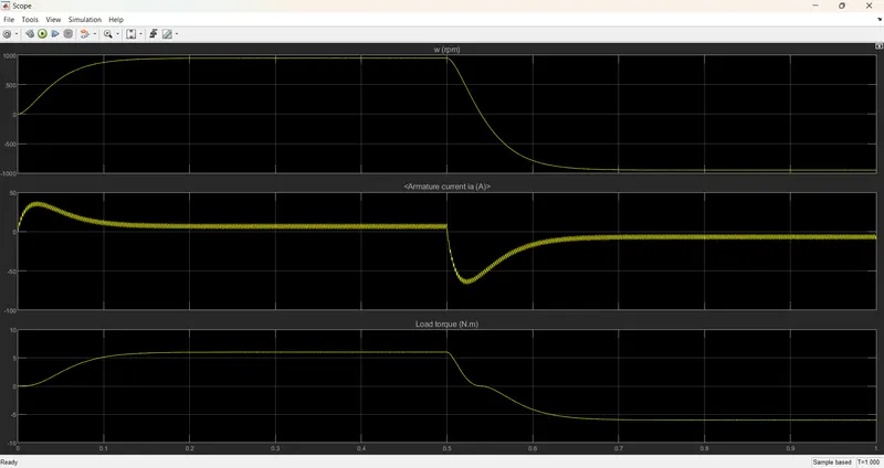
In this Speed in rpm, Armature current and Load torque.
B. Comment on the armature current shoot-up from the scope results.
When provide the armature voltage controlled through the circuit the output at P1,P2,P3,P4 are the signal which is goes to IGBT for operating.
P1 signal for Q1,P2 for Q2,P3 for Q3 and P4 for Q4 these arrangment are use to operate.Scope result below where the signal goes to ckt.
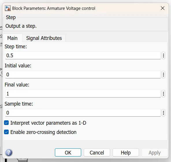
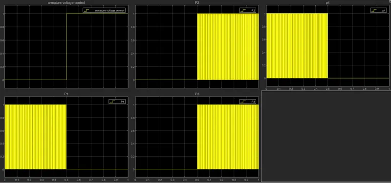
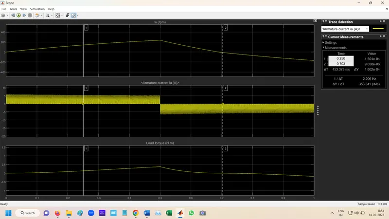
Result:- After run the simulation for 1 sec the scope result are below
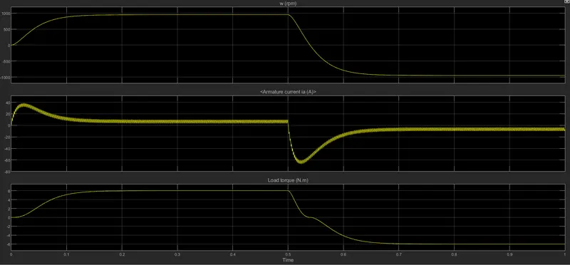
In this Armature current positive then armature voltage control is at 0.at this condition current starting almost 60A the arund 6 A.
When its switch to from 0 to 1 at 0.5 sec armature current increse rappidly to almost -60A then -7A current.
at that condition pulse width is 75%.
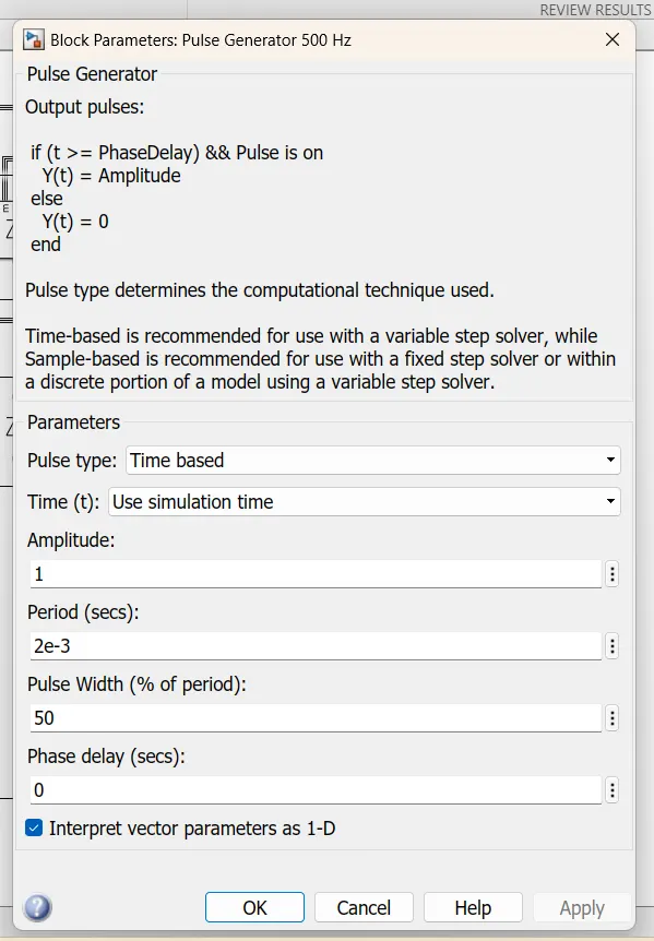
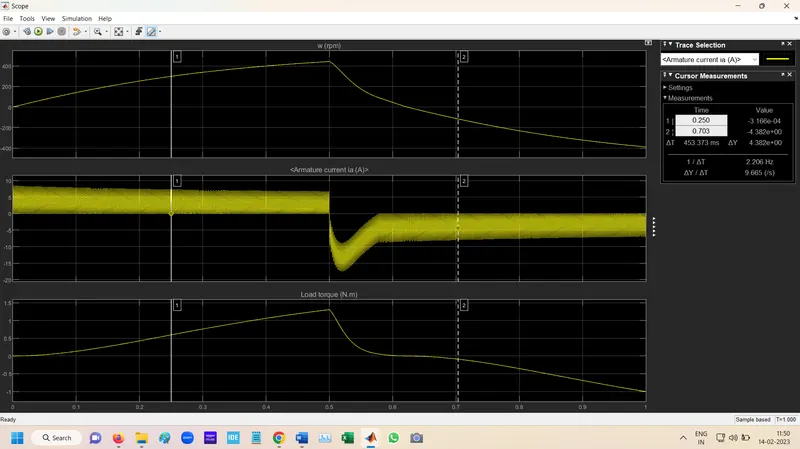
At 50% Pulse
At 50% pulse width current value of armature is decresed at Sudden decrece at 05 sec is around -15 A.
At 35%
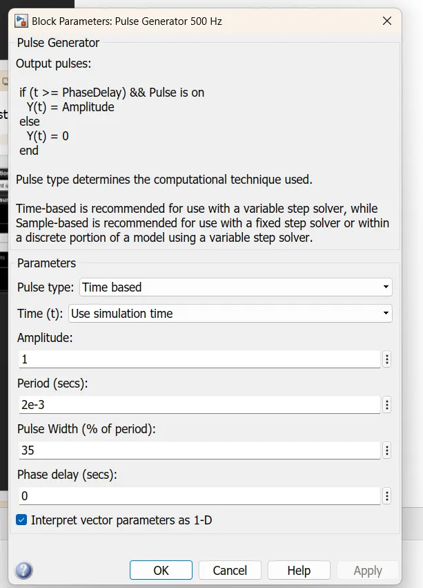
At 35% pulse width Armature current sudden decrese is done. its negative after 0.5 sec but its alomst same.
C. Refer to the help section of ‘The Four-Quadrant Chopper DC Drive (DC7) block’. Compare it with the H-bridge model.
Solution:-
| S.no. | The Four-Quadrant Chopper DC Drive (DC7) block | The H-bridge model |
| 1 | Its has four operating modes Forward Motoring,Forward breaking,Reverse Motoring,Reverser braking. | It has two operating modes Forward and Reverse. |
| 2 | The Four quardrant chopper is electronics switch that is used to interupt one signalunder the control of another. | H bridge is a electronic circuit that switch the polarity of voltage applied to then load. |
| 3 | It's have regenrative breaking feature. | It doesn't have regenrative breaking feature. |
| 4 | In this Speed Regulator and current regulator is used. | In this Speed Regulator and current regulator is not used. |
| 5 | It's better efficent than h bridge. | It's less efficient than Four quardrent chopper. |
| 6 |
It's used in Compressor, pump and fan type load requires operation. Transportation drives require operation in both directions. |
its used in Robotics and applicatin where motor forword and backward is required |
Question 02. Develop a 2-quadrant chopper using simulink & explain the working of the same with the relevant results.
Solution:-
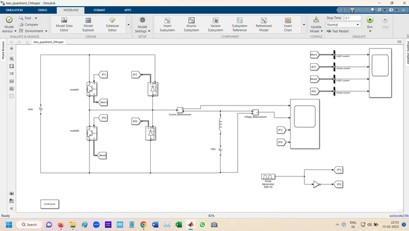
Simulation Model
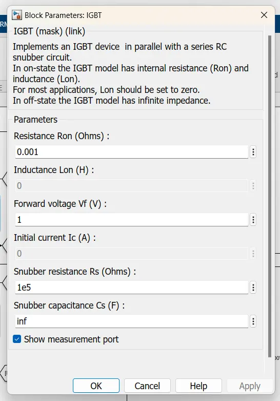
IGBt Parameters
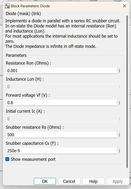
Diode parameters setting
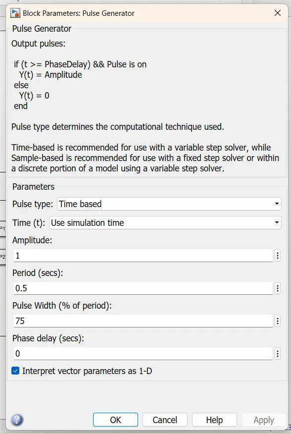
Pulse Generator settings
In this two Quadrant chopper will be always positive but the the average load current might be positive or negative.
For regenrative braking and motoring use these type of chhopper used.
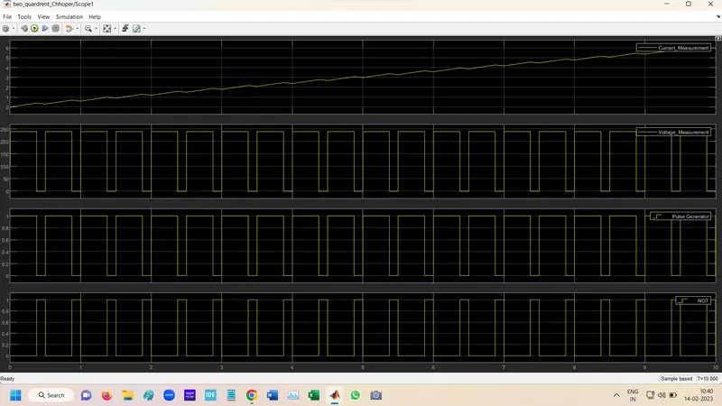
when the chopper Ch1 is on the current flows from source to load and inductore store energy.
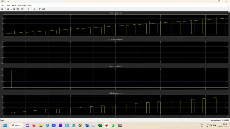
when ch1 tuen off the freewheel diode starts conducting. the direction of load current is negative.
Result:-
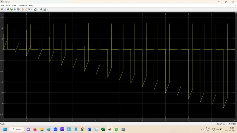
Scope output voltage, current, Igpt gate pulse signal at scope at 75% pulse width
Scope
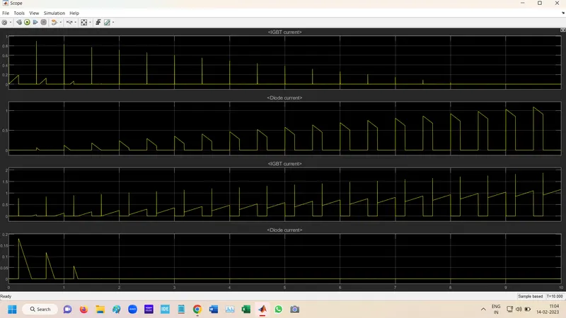
In this scope IGBT and diode current output scope at 75% pulse width
Source Current scope at 75% pulse width
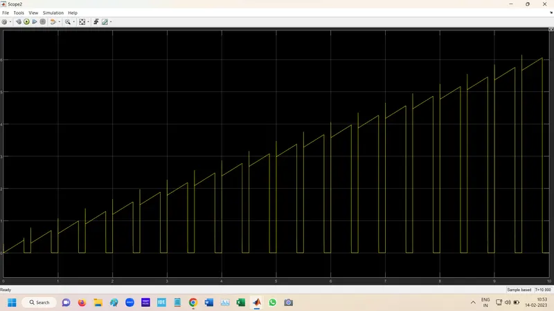
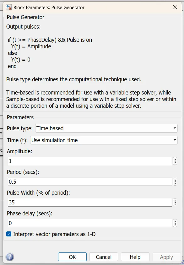
Scope output voltage, current, Igpt gate pulse signal at scope at 35% pulse width
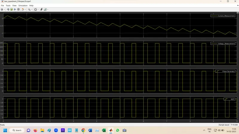
In this scope IGBT and diode current output scope at 35% pulse width
Source Current scope at 35% pulse width
Question 03. Explain in a brief about operation of BLDC motor.
Solution:-
BLDC motor:- A brushless DC motor (known as BLDC) is a permanent magnet synchronous electric motor which is driven by direct current (DC) electricity and it accomplishes electronically controlled commutation system (commutation is the process of producing rotational torque in the motor by changing phase currents through it at appropriate times) instead of a mechanically commutation system. BLDC motors are also referred as trapezoidal permanent magnet motors.
BLDC motor employs electrical commutation with permanent magnet rotor and a stator with a sequence of coils. In this motor, permanent magnet (or field poles) rotates and current carrying conductors are fixed.
The armature coils are switched electronically by transistors or silicon controlled rectifier at the correct rotor position in such a way that armature field is in space quadrature with the rotor field poles. Hence the force acting on the rotor causes it to rotate.
Hall sensors or rotary encoders are most commonly used to sense the position of the rotor and are positioned around the stator. The rotor position feedback from the sensor helps to determine when to switch the armature current.
Construction of BLDC Motor:-
BLDC motors can be constructed in different physical configurations. Depending on the stator windings, these can be configured as single-phase, two-phase, or three-phase motors. However, three-phase BLDC motors with permanent magnet rotor are most commonly used.
Operation of BLDC motor:-
BLDC motor works on the principle similar to that of a conventional DC motor, i.e., the Lorentz force law which states that whenever a current carrying conductor placed in a magnetic field it experiences a force. As a consequence of reaction force, the magnet will experience an equal and opposite force. In case BLDC motor, the current carrying conductor is stationary while the permanent magnet moves.
When the stator coils are electrically switched by a supply source, it becomes electromagnet and starts producing the uniform field in the air gap. Though the source of supply is DC, switching makes to generate an AC voltage waveform with trapezoidal shape. Due to the force of interaction between electromagnet stator and permanent magnet rotor, the rotor continues to rotate.
Consider the figure below in which motor stator is excited based on different switching states. With the switching of windings as High and Low signals, corresponding winding energized as North and South poles. The permanent magnet rotor with North and South poles align with stator poles causing motor to rotate.
Observe that motor produces torque because of the development of attraction forces (when North-South or South-North alignment) and repulsion forces (when North-North or South-South alignment). By this way motor moves in a clockwise direction.
Here, one might get a question that how we know which stator coil should be energized and when to do. This is because; the motor continuous rotation depends on the switching sequence around the coils. As discussed above that Hall sensors give shaft position feedback to the electronic controller unit.
Based on this signal from sensor, the controller decides particular coils to energize. Hall-effect sensors generate Low and High level signals whenever rotor poles pass near to it. These signals determine the position of the shaft.
BLDC simply connection with transistor:-
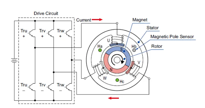
In this six thyrister is use for providing signal to BLDC motor to provide supply.Tru + and Tuu- provide U coil supply, similarly Trv+ and Trv- is used to provide supply to V coil and Trw1 and Trw- is used to provide supply to w coil.
Ha, Hb & Hc this 3 are hall sensor or Magnetic pole sensor which provide Signal to controller when north pole passes near the sensor.
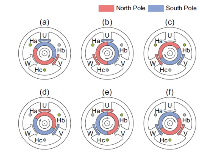
In above diagram
1) at 0 to 60 degree rotor angle Thyristor Tru+ provide +v voltage to u coil and Trv- provide -v supply to V coil of BLDC staror part so u pole genrate
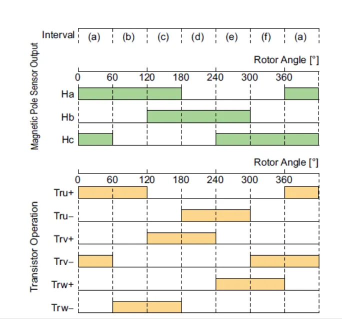
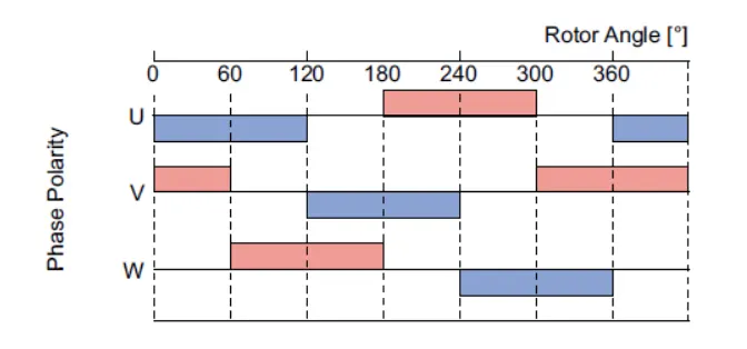
In above digram working describe in Below Table.
| S.No. |
Rotor Angle in Degree |
Transistor who provide the +ve volt supply |
Transistor who provide the -ve volt supply |
Current flows from the phase so magnetized as South pole of Coil |
Current flows to the phase or exit from so magnetized as North pole of Coil |
ON states for magnetic pole sensors |
Rotor South pole attraction & repel |
Rotor North pole attraction & repel |
RemarkS |
| 1 | 0 to 60 | Tru+ | Trv- | U coil | V coil | Ha & Hc |
Coil U repel & Coil v attract |
Coil v repel | When Coil U repel & coil V attract of South pole of rotor and Coil V repel North pole if rotor so causes the rotor to rotate clockwise. |
| 2 | 60 to 120 | Tru+ | Trw- | U coil | W coil | Ha | Coil U repel | Coil W repel & Coil U attract | When Coil U repel of South pole of rotor and Coil W repel & coil U attract North pole if rotor so causes the rotor to rotate next clockwise cycle. |
| 3 | 120 to 180 | Trv+ | Trw- | V coil | W coil | Ha & Hb | Coil W attract & Coil V repel | Coil W repel | When Coil V repel & coil W attract of South pole of rotor and Coil W repel North pole if rotor so causes the rotor to rotate next clockwise cycle. |
| 4 | 180 to 240 | Trv+ | Tru- | V coil | U coil | Hb | Coil V repel | Coil V attrat & Coil U repel | When Coil V repel of South pole of rotor and Coil U repel & coil V attract North pole if rotor so causes the rotor to rotate next clockwise cycle. |
| 5 | 240 to 300 | Trw+ | Tru- | W coil | U coil | Hb & Hc | Coil U attract & Coil W repel | Coil U repel | When Coil W repel & coil U attract of South pole of rotor and Coil U repel North pole if rotor so causes the rotor to rotate next clockwise cycle. |
| 6 | 300 to 360 | Trw+ | Trv- | W coil | V coil | Hc | Coil W repel | Coil W attract & Coil V repel | When Coil W repel of South pole of rotor and Coil V repel & coil W attract North pole if rotor so causes the rotor to rotate next clockwise cycle. |