Week-6 Challenge: EV Drivetrain
Question no. 01:- Which types of power converter circuits are employed in electric and hybrid electric vehicle?
Solution:-
Types of power converter circuits:- there is mainly 4 type of converter uses.
1) AC to DC Converter or Rectifier
2) DC to AC Converter or Inverter
3) DC to DC Converter or Chopper
4) AC to AC Converter
AC to DC Converter or Rectifier :- In this converter circuit AC voltage is converted into required DC voltage.
this conversen is mostly used for charging the electric vehical from AC power source throught rectifier circuit arrangent where rectifier is convert AC voltage into required DC voltage.
- In "Series Hybrid vehical" and "Series Parallel Hybrid Vehical" IC engine is connected with Generator which genrate ac voltage. for battery charging use rectifier or AC to DC converter is used.
- In "Plug in Hybrid Vehical" for battery charging use Ac to DC converter.
- In "Pure Electrical vehical" battery charging also used AC to DC Converter.
- In Regenrative breaking condition when vehical motor produce ac voltage if when use that power for the battery charging of vehical so AC to DC converter is also used in that condition.
DC to AC Converter or Inverter :- In this converter circuit DC voltage is converted into required AC voltage.
this converson is mostly used for the electric vehical where vehical motor is ac motor when power required from DC power source or battery to provided ac power to AC vehical motor through Inverter circuit arrangent where Inverter is convert DC voltage into required AC voltage.
- In "Series Hybrid vehical" and "Series Parallel Hybrid Vehical" ,"Plug in Hybrid Vehical" when power is required for ac vehical motor so DC to AC converter is used.
- In "Pure Electrical vehical" also used DC to AC Converter for AC electric motor drive.
DC to DC Converter or Chopper:- In this converter circuit DC voltage is converted into required DC voltage.
If input DC voltage is low then output DC voltage is called "Stepup Chopper".
If input DC voltage is high then output DC voltage is called "Stepdown Chopper".
this stepdown chopper used where dc supply for auxilaiy system those worked on low dc voltage level like sound system,light, other controller for this required to convert Vehical battery to low voltage according requirement.
this chopper ckt where is used if DC source is provide power for battery charging for protection or required power according electrical vehical system used chopper ckt.
AC to AC Converter :- In this converter circuit AC voltage is converted into required AC voltage.
this circuit is used where AC voltage source to another AC supply for different frequency or voltage of ac required so used this conveter.
Question no. 02:- An Electric Vehicle's powertrain with 72V battery pack in shown in the diagram below. The duty ratio for acceleration operation is 'd1' and for the braking operation the duty ratio is 'd2'.
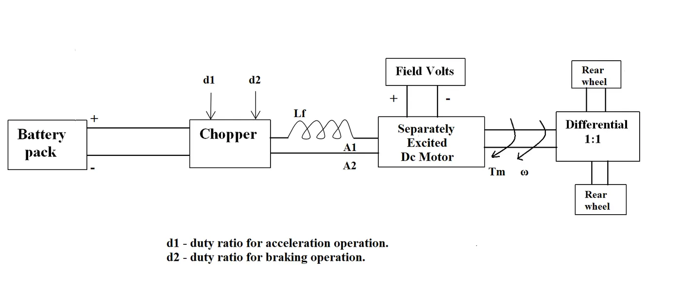
The other parameters of the electric vehicle is given below,
Motor and Controller Parameters:
Rated Armature voltage= 72 V
Rated armature current= 400 A
Ra= 0.5Ω, KΦ= 0.7 Volt second
Chopper Switching frequency= 400 Hz
The vehicle speed-torque characteristics are given by the below equation

What is EV steady state speed if duty cycle is 70%?
Solution:-
Given Data
Battery pack voltage Vbatt= 72V
Motor and Controller Parameters:
Rated Armature voltage = 72 V
Rated armature current = 400 A
Ra= 0.5Ω, KΦ= 0.7 Volt second
Chopper Switching frequency= 400 Hz
Condition :- EV steady state speed if duty cycle is 70% for that condition Vavg is
Vavg =Vbatt*duty cycle
Vavg = 72*0.7 = 50.4 volt
DC machine motor torque speed equation at 100% duty cycle
Torque = {(V*K_phi)/Ra}-{((k_phi)^2*w)/Ra}
Torque = {(72*0.7)/0.5}-{(0.7*0.7*w/0.5}
Torque = 100.8 - 0.98 *w ............................equation no(01)
DC machine motor torque speed equation at 70% duty cycle
Torque = {(V*K_phi)/Ra}-{((k_phi)^2*w)/Ra}
Torque = {(50.4*0.7)/0.5}-{(0.7*0.7*w/0.5}
Torque = 70.56 - 0.98 *w ............................equation no(02)
Given equation in Question at 100% duty cycle
Torque of vehical = 24.7 +(0.0051)w^2 ........................equation no(03)
From equation no(01) and equation no (03)
100.8-0.98*w=24.7+(0.0051)*w^2
0.0051*w^2+0.98w-76.1=0
when solve this equation there are get two values by use of quadratic equation
Quadratic Equation in Standard Form: ax2 + bx + c = 0 ;Quadratic Formula: x = {−b ± √(b2 − 4ac)}/2a
First value is w=-249.54 rad/sec
Second value is w= 61.23 rad/sec
From equation no(02) and equation no (03)
70.56-0.98*w=24.7+(0.0051)*w^2
0.0051*w^2+0.98w-45.86=0
when solve this equation there are get two values
First value is w=-229.14 rad/sec
Second value is w= 40.83 rad/sec
Question no. 03:- Develop a mathematical model of a DC Motor for the below equation using Simulink.

Solution:- Given equation is rearrange then model Simulation
Simulation Model:-
T={(V*K_phi)/Ra}-{(w*K_phi*K-phi)/Ra}
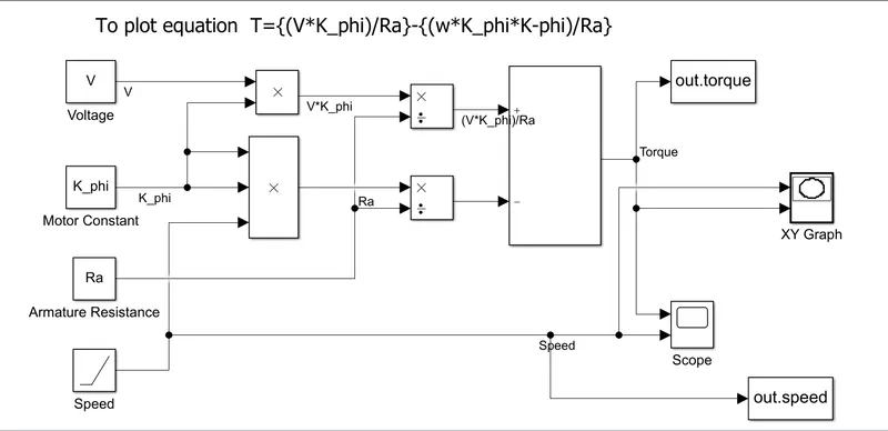
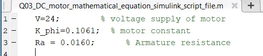
Input Value :- Provide value of Voltage,motor constant and Armature resistance through matlab script file.
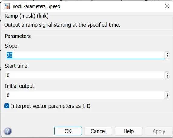
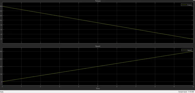
Speed value provided through Ramp signal
parameter of ramp signal is below
After this first of all run script file then run the simulation for 10 sec.
Result:-After run the simulation after 10sec Scope Result are
Xy Graph output:-In this graph show relation between X Axis sghow Speed and Y axis show Torque.
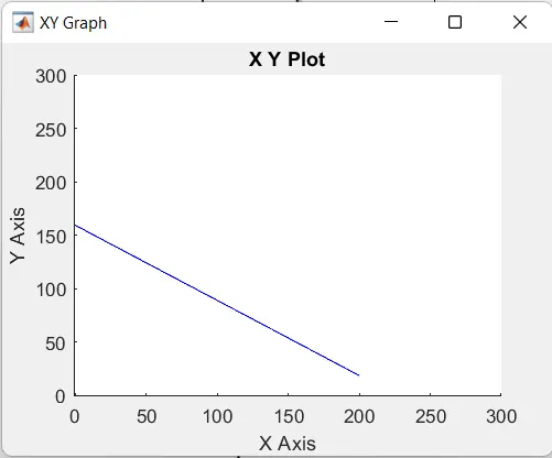
Observation:- When Speed is increase then torque value is decreases.
Question no. 04:- Refer to the blog on below topic:
Induction Versus DC brushless motors by Wally Rippel, Tesla
Explain in brief about author’s perspective.
Solution:-
Author are describe about induction machine and brushless dc machine comparision. So below comparision come from the description.
| S.No. | Brushless DC Machine | Induction Machine |
| 1 | Brushless machines, the rotor includes two or more permanent magnets that generate a DC magnetic field | The induction rotor has no magnets – just stacked steel laminations with buried peripheral conductors that form a “shorted structure.” |
| 2 | In turn, this magnetic field enters the stator core (a core made up of thin, stacked laminations) and interacts with currents flowing within the windings to produce a torque interaction between the rotor and stator. | Currents flowing in the stator windings produce a rotating magnetic field that enters the rotor. In turn, the frequency of this magnetic field as “seen” by the rotor is equal to the difference between the applied electrical frequency and the rotational “frequency” of the rotor itself. |
| 3 | As the rotor rotates, it is necessary that the magnitude and polarity of the stator currents be continuously varied – and in just the right way - such that the torque remains constant and the conversion of electrical to mechanical energy is optimally efficient. The device that provides this current control is called an inverter. Without it, brushless motors are useless motors. | Accordingly, an induced voltage exists across the shorted structure that is proportionate to this speed difference between the rotor and electrical frequency. In response to this voltage, currents are produced within the rotor conductors that are approximately proportionate to the voltage, hence the speed difference. Finally, these currents interact with the original magnetic field to produce forces – a component of which is the desired rotor torque. |
| 4 | The stators for the DC brushless motor are three sets of “distributed windings” that are inserted within the stator core. | The 3-phase induction motor also same stator are virtually identical. |
| 5 | In contrast, a brushless DC motor produces no starting torque when directly connected to fixed frequency utility power. They really need the aid of an inverter whose “phase” is maintained in step with the angular position of the rotor. | When a 3-phase induction motor is connected to utility type 3-phase power, torque is produced at the outset; the motor has the ability to start under load. No inverter is needed. |
| 6 | Brushless DC motor are not compatible with conventional utility power it's required inverter. | Induction motors are directly compatible with conventional utility power is the main reason for their success. |
| 7 | Brushless DC motor operate with AC, with inverter. | Induction motors cannot operate from DC,AC is must required. |
| 8 | In this feedback control required. | Add an inverter (without any feedback control) and it becomes possible to power an induction machine from a battery or other DC source |
| 9 | Torque performance is high compared with Induction machines. | Torque performance is low compared with DC machines. |
| S.No. | Brushless DC Machine | Induction Machine |
| 1 | DC brushless drives require an absolute position sensor. | Induction drives require only a speed sensor. |
| 2 | In this much less rotor heat is generated with the DC brushless drive. | In this rotor heat is generated with the Induction machine. |
| 3 | The DC brushless drive can also operate at unity power factor. | The best power factor for the induction drive is about 85 percent. |
| 4 | Rotor cooling is easier and peak point efficiency is generally higher for this drive. | |
|
5 |
In this is no easy way of changing B with permanent magnets. | Induction machines have no magnets and the magnetic field strength (B) fields are “adjustable,” since B is proportionate to V/f (voltage to frequency). |
| 6 | In this some difficulty due permanent magnet is not easy to change B. | The induction machine when operated with a smart inverter has an advantage magnetic and conduction losses can be traded such that efficiency is optimized. |
| 7 | DC brushless, as machine size grows, the magnetic losses increase proportionately and part load efficiency drops. | In the induction machine size grows, losses do not necessarily grow. |
| 8 | Permanent magnet (PM) rotors are also difficult to handle due to very large forces that come into play when anything ferromagnetic gets close to them. | In the Induction machine magnetic feild can easily controlled. |
| 9 | Permanent magnets are expensive. | Induction motors will likely retain a cost advantage over PM machines. |
| 10 | it's less difficult to control. | Induction machines are more difficult to control. |
| 11 | Less complex and difficult to understand with the Induction machine. | The control laws are more complex and difficult to understand. |
| 12 | Achieving stability over the entire torque-speed range and over temperature is less difficult with DC brushlessinduction than with induction. | Achieving stability over the entire torque-speed range and over temperature is more difficult with induction than with DC brushless. |
| 13 | Development cost is less than Induction machine. | In this Development cost high compair than DC brushless. |
Similarity:-
1) DC brushless and induction drives use motors having similar stators.
2)Both drives use 3-phase modulating inverters.The only differences are the rotors and the inverter controls. And with digital controllers, the only control differences are with control code.
Result:- On comparision both Brushless DC machine and Induction Machine both are almost equal. we can not say that all point goes to any one of the machine or get high hight compare with each.
so final result is that on the requirement of the machine according to their application we can use. there is no one sided winner both are almost equal.