Project 1 Mechanical design of battery pack
Project 1 Mechanical design of battery pack
AIM : To Build a Battery pack of capacity 18 kWh for a Cell Model: ANR26650M1-B
Prepare a detailed battery pack drawing along with its enclosure. State your assumptions.
Solution:
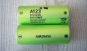
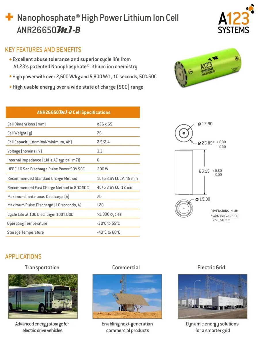
Here we are taking A123 systems Cell Model: ANR26650M1-B to study and build a battery pack of capacity 18 kwh.
Cell Specifications of Model ANR26650M1-B
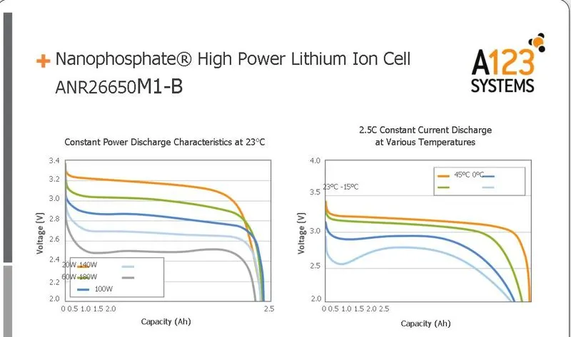
Here we are using the cell of chemistry type LiFePO4(Lithium iron phosphate).so,the characteristics of LiFePO4 is quite different than other cell chemistries which are explained in detail.
Lithium iron phosphate has a cathode of iron phosphate and an anode of graphite. It has a specific energy of 90/120 watt-hours per kilogram and a nominal voltage of 3.20V or 3.30V. The charge rate of lithium iron phosphate is 1C and the discharge rate of 1-25C.
Structure and performance of the LiFePO4 cathode material: from the bulk to the surface
Abstract
Currently, LiFePO4 is one of the most successfully commercialized cathode materials in the rechargeable lithium-ion battery (LIB) system, owing to its excellent safety performance and remarkable electrochemical properties and is expected to have a broader market in the near future. Although it is widely recognized that the crystalline structure of a cathode material largely dictates its electrochemical properties (e.g. capacity, cycle life and rate capabilities), this intrinsic connection in LiFePO4 has not been systematically reviewed. Different from the previous reviews, which mainly focus on the improvement of electrochemical performance by all kinds of techniques, in this review, the relationship between its electrochemical performance and bulk/surface structure is reviewed and discussed. First, it is revealed that the intra-particle Li+ transfer is influenced by several properties of the bulk, including crystalline structures, antisite defects and electronic structures. Next, it is demonstrated that the surface/interfacial structures of LiFePO4, which can be reconstructed artificially or spontaneously, also have great impacts on the performances. Lastly, the intrinsic connection between the structure and performance is preliminarily established, showing brand-new perspectives on the strategy for further improvement and contributing to a comprehensive understanding of LiFePO4.
So what is Lithium Nanophosphate?
Nanophosphate® is a registered trademark for a Lithium Iron Phosphate battery technology that maximises the performance of the standard technology. The three main areas where Lithium Nanophosphate has distinct advantages over other Lithium Iron Phosphate batteries are listed below.
Power
is a positive electrode material of remarkable rate capability, critical to high power systems.
High power products are able to pulse at discharge rates as high as 100C and deliver superior power by weight or volume in a cost-effective solution. With their low impedance and thermally conductive design, high power cells can be continuously discharged at a 35C rate, a marked improvement over other rechargeable battery alternatives, and have consistent power over a wide state of charge (SOC) range.
Safety
Safety begins with chemistry and Nanophosphate is stable chemically, which provides the foundation for safe systems while meeting the most demanding customer requirements.
Multiple layers of protection are employed at the chemistry, cell and system level to achieve an energy storage solution with superior safety and abuse tolerance compared to metal oxide lithiumion chemistries.
Life
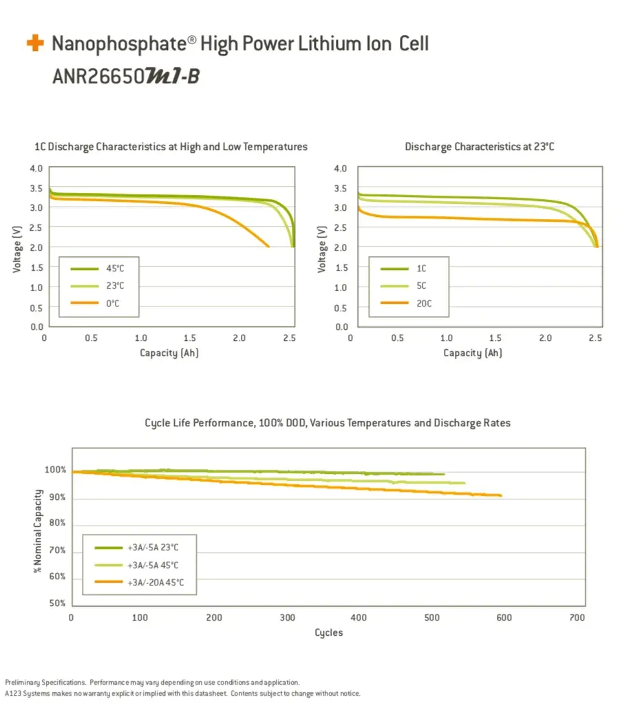
Nanophosphate technology delivers exceptional calendar and cycle life. At low rates our cells can deliver thousands of cycles at 100% depth of discharge (DOD), a feat unmatched by most commercial lithium ion cells. Even when cycled at 10C discharge rates, cells deliver in excess of 1,000 full DOD cycles. Not only does the technology retain its energy, it also retains its power capability. Not all lithium-ion technologies behave the same. The nanoscale structure of the Nanophosphate chemistry, for example, enables battery systems with higher power, increased abuse tolerance, longer life and the greater ability to maintain consistent power over a wide range of state-of-charge (SOC) as compared with competing lithium-ion and other chemistries.
Understanding the fundamental chemical differences between Nanophosphate and other technologies is necessary to develop a complete and accurate assessment of the optimal advanced battery system that will deliver the best performance for a given application.
Discharge characteristics of LiFePO4 (Lithium iron phophate cell )
Detailed Battery pack drawing along with enclosure for a capacity of 18 KWh of cell model ANR26650M1-B
Battery Pack Design
The purpose of a battery pack is to provide a convenient integrated power source for portable applications.The pack may fulfil several functions:-
- It enables higher voltage or higher capacity batteries to be built up from low voltage, low capacity cells.
- It houses a cell or a bank of cells together with the associated interconnections in a single convenient pack.
- It accommodates any necessary monitoring and electronic protection devices or circuits within the pack.
- It can accommodate additional circuitry such as indicator lights, heaters, cooling ducts and solar panels.
- It matches and meshes with the cavity in the product which the battery is intended to power providing both electrical and mechanical interfaces.
- It can provide unique electrical and mechanical interfaces to ensure compatibility both of the battery with the intended product and the charger with the battery.
Capacity and Voltage:
With a simple series chain of cells, the battery capacity in AmpHours is the same as the capacity of the individual cells since the current flows equally through all the cells in the chain.
High battery voltages are achieved by adding more cells in a series chain. The voltage of the battery is the voltage of a single cell multiplied by the number of cells in the chain. This does not increase the AmpHour capacity of the battery , but it increases the WattHour capacity, or the total stored energy, in proportion to the number of cells in the chain.
Battery capacity can increased through adding more parallel cells. This increases the AmpHour capacity as well as the WattHour capacity without increasing the battery voltage. For batteries with parallel chains the capacity of the battery is the capacity of the individual chain multiplied by the number of parallel chains.
Whereas cell voltage is fixed by the cell chemistry, cell capacity depends on the surface area of the electrodes and the volume of the electrolyte, - that is, the physical size of the cell. If at all possible the number of cells in a pack should be minimised to simplify the design and to minimise potential reliability problems. Fewer cells require fewer support electronics. Thus parallel chains should be avoided by specifying the highest capacity cells available. Design issues for multi-cell batteries are considered further in the section on Cell Balancing.
Cell Configuration:
The ultimate shape and dimensions of the battery pack are mostly governed by the cavity which is planned to house it within the intended application. This in turn dictates the possible cell sizes and layouts which can be used. Prismatic cells provide the best space utilisation, however cylindrical cells provide simpler cooling options for high power batteries. The use of pouch cells provides the product designer more freedom in specifying the shape of the battery cavity permitting very compact designs.
The orientation of the cells is designed to minimise the interconnections between the cells.
Battery Pack Energy capacity is 18KWh for this we are calculating the no of cells required in series and parallel combination and also the Ampere Hour Capacity.
Here we are designing a high voltage battery pack for a small 2 seater electric car and its range is 300km. For this calculation the assumed voltage is 200v which is the nominal voltage for series connection.
As we assumed the vehicle range is 300km then the Average energy per km is
Total energy of battery pack/Range in km = 18000/300 = 60 Wh/km
Assuming the complete battery pack voltage : V = 200
Nominal voltage of each cell : 3.3V
Total battery pack voltage / Nominal cell voltage = 200/3.3 = 60V --------(1)
Total Energy capacity / Total battery pack voltage = 18000 watts / 200 V = 90Ah
Dicharge Current Capacity of Total Batttery Pack : 90Ah
Nominal cell capacity : 2.5Ah
Total battery pack capacity / Nominal cell capacity = 90Ah / 2.5Ah = 36Ah -----------(2)
From (1) we get the no of cells required in series = 60S
From (2) we get the no of cells required in parallel = 36P
The Battery pack specifications are : Energy capacity = 18KWh
Nominal Voltage = 200V
Maximum capacity = 90Ah
Pack combination = 60S36P
Total no of cells = 60*36 = 2160 cells
In series connection the voltage increases and the current remains the same = 60*3.3 = 200Volts
In parallel connection the current increases and the voltage remains the same = 2.5*36 = 90Amp
Mass of battery pack = Total no of cells * Mass of single cell
= 2160 *0.076
= 164.16 kg
Total volume of battery interms of area=Total no of cells in a battery pack * volume of single cell
= 2160*0.0345
= 72.89 m^3
Considering the Single cell dimensions :
Diameter = 26 mm = 0.026m
Length = 65 mm = 0.065m
Mass = 76g = 0.076 kg
single cell voltage = 3.3V
capacity = 2.5 Ah = 1C Rate
Max continuous charge rate = 10A @ 4C Rate
Single cell volume = 3.14*0.026^2*0.065
=0.03451 m^3
The volume of each cell is used to find the total volume of battery pack = cell capacity*cell voltage
= 2.6*3.3
= 8.58 Wh
Energy density of single cell is used to calculate the total energy density of battery pack:
volumetric energy (Wh/m^3) = single cell energy / volume of each cell
= 8.58 Wh/0.03451 m^3
= 248.62 Wh/m^3
Gravimetric energy (Wh/Kg) = single cell energy / Mass of each cell
= 8.58 Wh/0.076 kg
= 112.89 Wh/kg
cell peak current(A) = Max charge current(C rate) * single cell capacity
= 10*2.5
= 25A
Battery pack peak current(A) = Cell peak current * No of cells connected in parallel
= 25*36
= 900 A
Battery pack peak power(W) = Battery pack peak current*Voltage if cells connected in series
= 900*200
= 180 kw
Battery Pack Assembly:
The design of the outer package or housing of the battery depends to a great extent on the components it has to accommodate and the physical protection it has to provide for them. These components are not just the cells, but also protection devices, electronic circuits, interconnections and connectors which must all be specified before the final battery case can be designed. For high power, high energy batteries robust packaging is required for safety reasons.
Cell holder dimensions
Height = 10mm
length = 29mm
width = 29mm
weight = 5gm
Arrangement of cells in 60S30P together is not the best arrangement as it will take
29mm*60 cells =1740mm For 60 cells in series
29mm*36 cells =1044mm For 36 cells in parallel so, a total of (1740*1044) space required and all the cells in a single matrix will lead to poor thermal management as we are employing the air cooled technique in the battry pack the ventilators will not be able to cool the inner cells as the air will not reach till the inner cells.
Also, according to the18KWh capacity,the application might be in a small 2 seater Electric car the area taken by the battery pack assembly is 1.74*1.04 meters.
The solution for both the space required and the thermal management of battery pack is to create a module of 10S6P. This will create 33V 15Ah module. Arranging such 10S6P modules in 6S6P manner will create a 60S36P array giving 198V 90Ah.
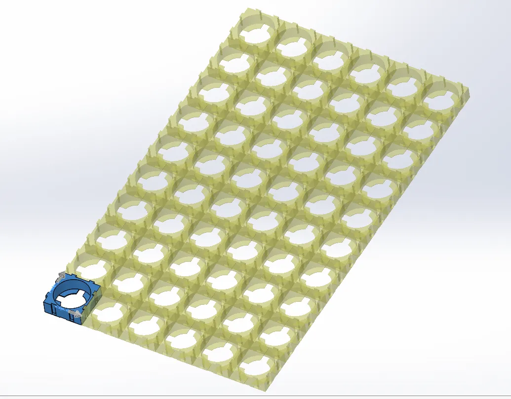
Step 1: Arange all the cell holders in 10S6P manner
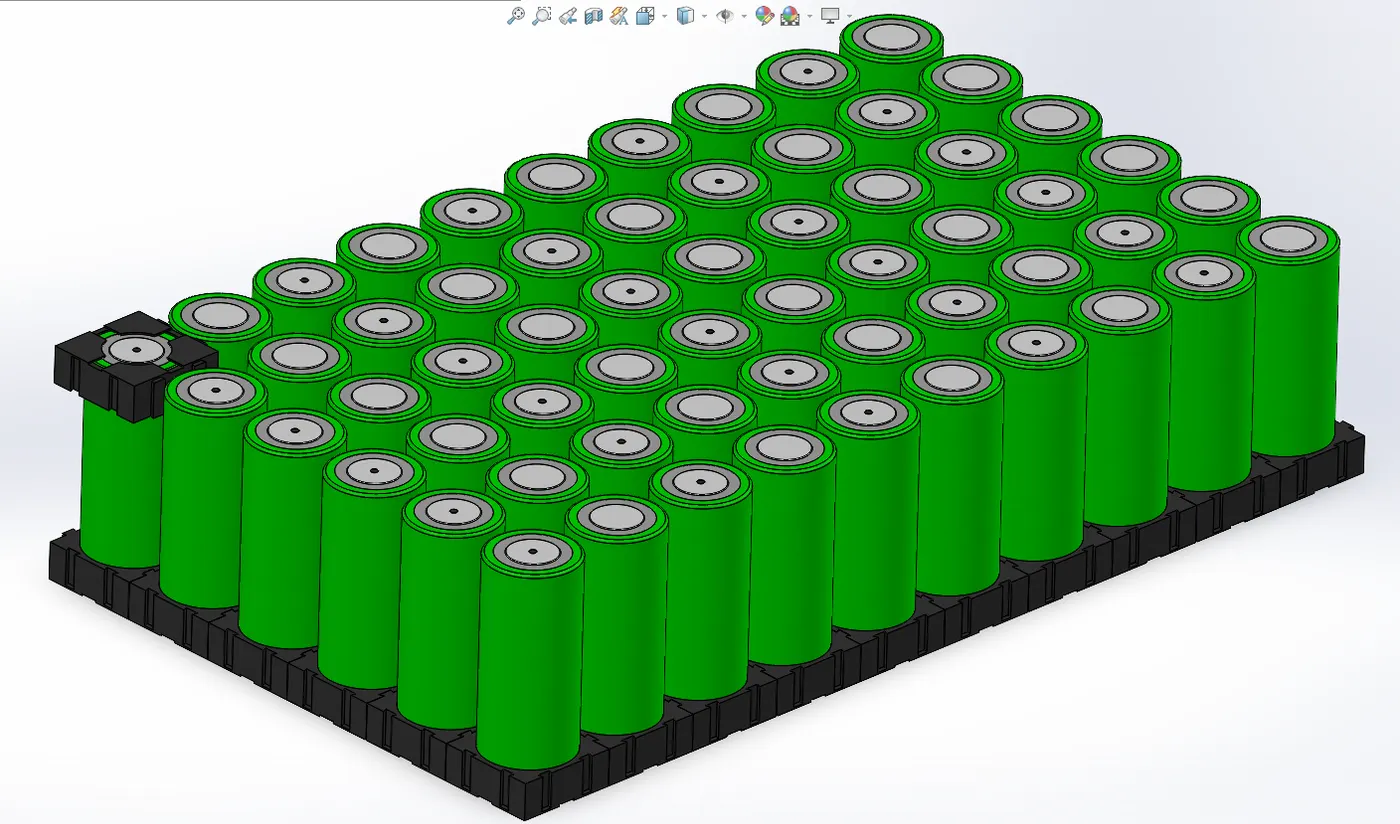
Step 2: Arange all the cells in cell holders in 10S6P manner
Step3: Add cell holders on the upper side of cells and also add nickel strips for series and parallel connections
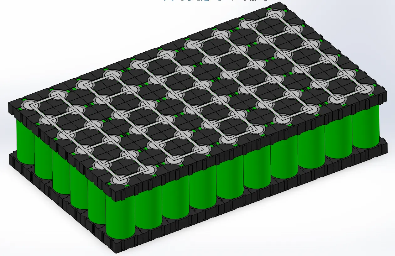
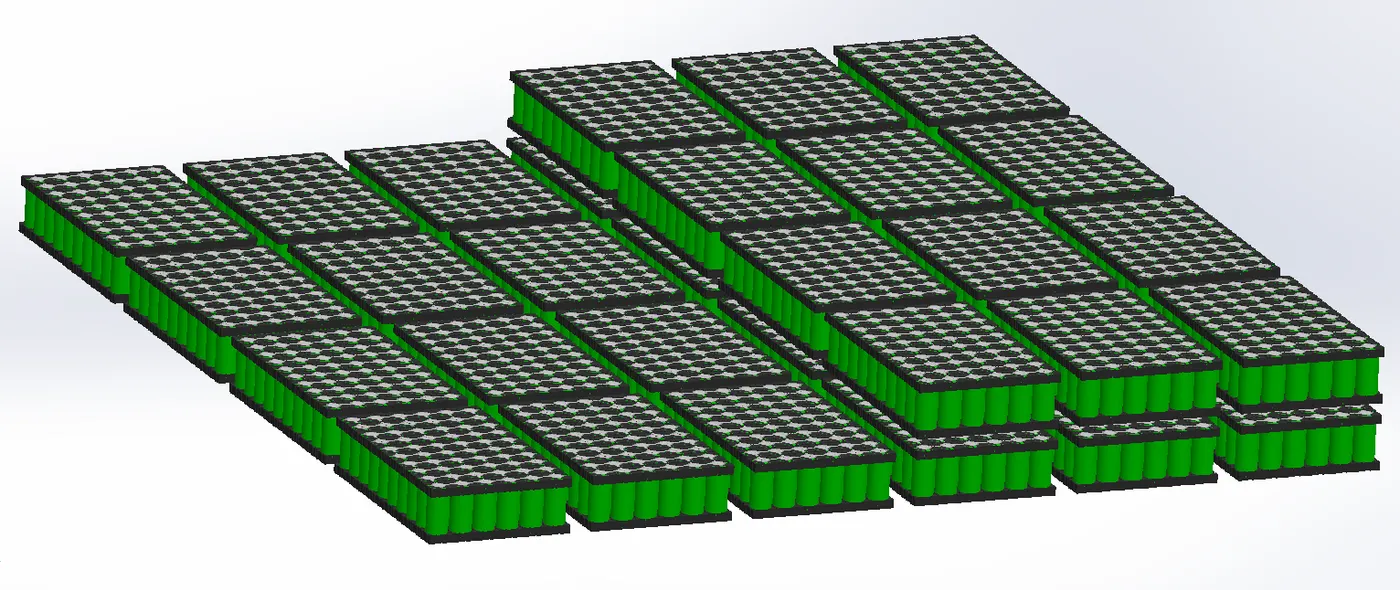
Now one module is complete and such 36 modules are required for 6 series and 6 parallel connection. The below image shows the arrangement of 36 such modules this completes the battery pack assembly with the required combination of cells.
Thermal Design:
Thermal management is a major issue in high power designs, particularly for automotive applications. See details in the Thermal Management section. As part of the battery system, it may be necessary to provide air or water cooling ducts, pumps or fans and heat exchangers for high temperature working or heaters for operating in low temperature environments. The layout of the cells should be conducive to managing heat flows within the pack.
We have used Air-Cooling Technique in the battery pack assembly
Cooling (and heating) the battery cells by circulating air within the sealed battery pack through a heat exchanger connected to the car's HVAC system, and then over the cells can achieve the same or even better thermal control as Tesla's current liquid cooling scheme. The difficulty is that quite large volumes of air must be moved past the cells, and that requires large cooling passages and much larger battery modules to hold a given number of cells.
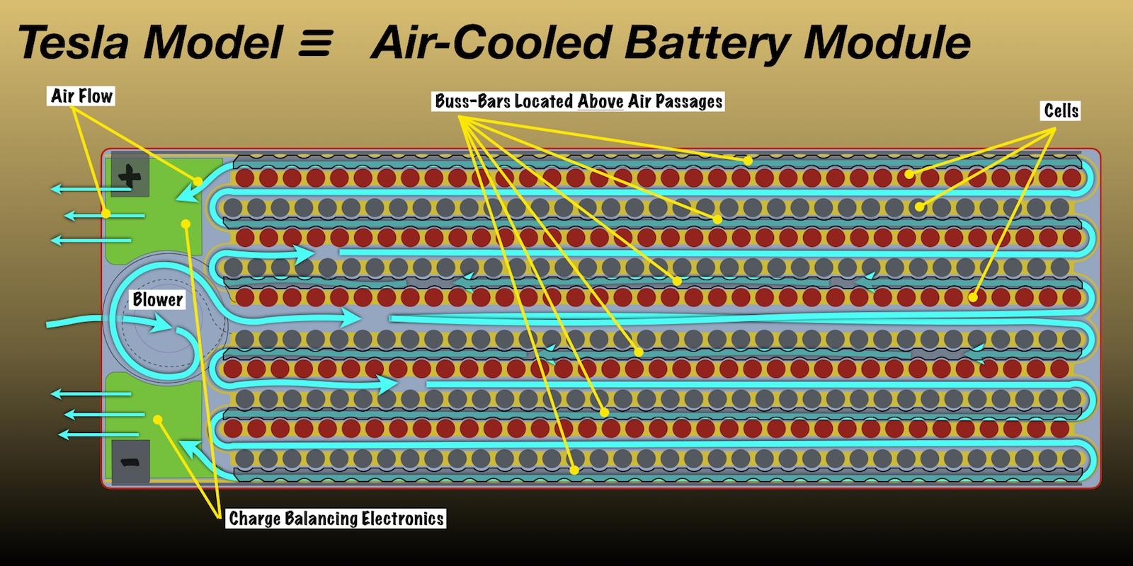
This air-cooled battery module is sized for extreme SuperCharging.
Air-Cooled Module Is Different
Air-cooled battery modules offer a number of advantages and some shortcomings when compared with liquid cooled modules such as Tesla currently uses. The Air-cooled module is much simpler because air being an electrical insulator can be in direct contact with the cells without short circuiting the battery. Water-glycol liquid coolant is electrically conductive so special thermally conductive and electrically insulating materials must separate battery cells and coolant at all times.
Liquid-cooled modules require coolant tubes, fittings, insulating coverings and the like to channel coolant amongst the cells. Air, on the other hand, can be routed through the array of cells by nothing more than simple passages molded into the plastic module housing.
The drawback is that air being less dense requires larger channels between cells making the air-cooled module substantially larger.
We will consider only battery modules containing lots of little round cells because that is the type of cell Tesla has committed to, unlike legacy carmakers who mostly prefer using fewer, bigger flat prismatic or pouch cells. Incidentally, we will in a bit, see once again, why Tesla's is the right choice.
In a Tesla style battery module, cells are connected in parallel to form cell groups, and these groups are then connected in series. Small gage wires connect each cell's positive and negative terminal to a buss-bar that connects the cell to other cells in its parallel cell group. By arranging the air-cooled module with each group of parallel cells in single-file, and spacing the cell groups apart to form cooling air passages, the buss-bars can be aligned with the cooling air passages as illustrated below.
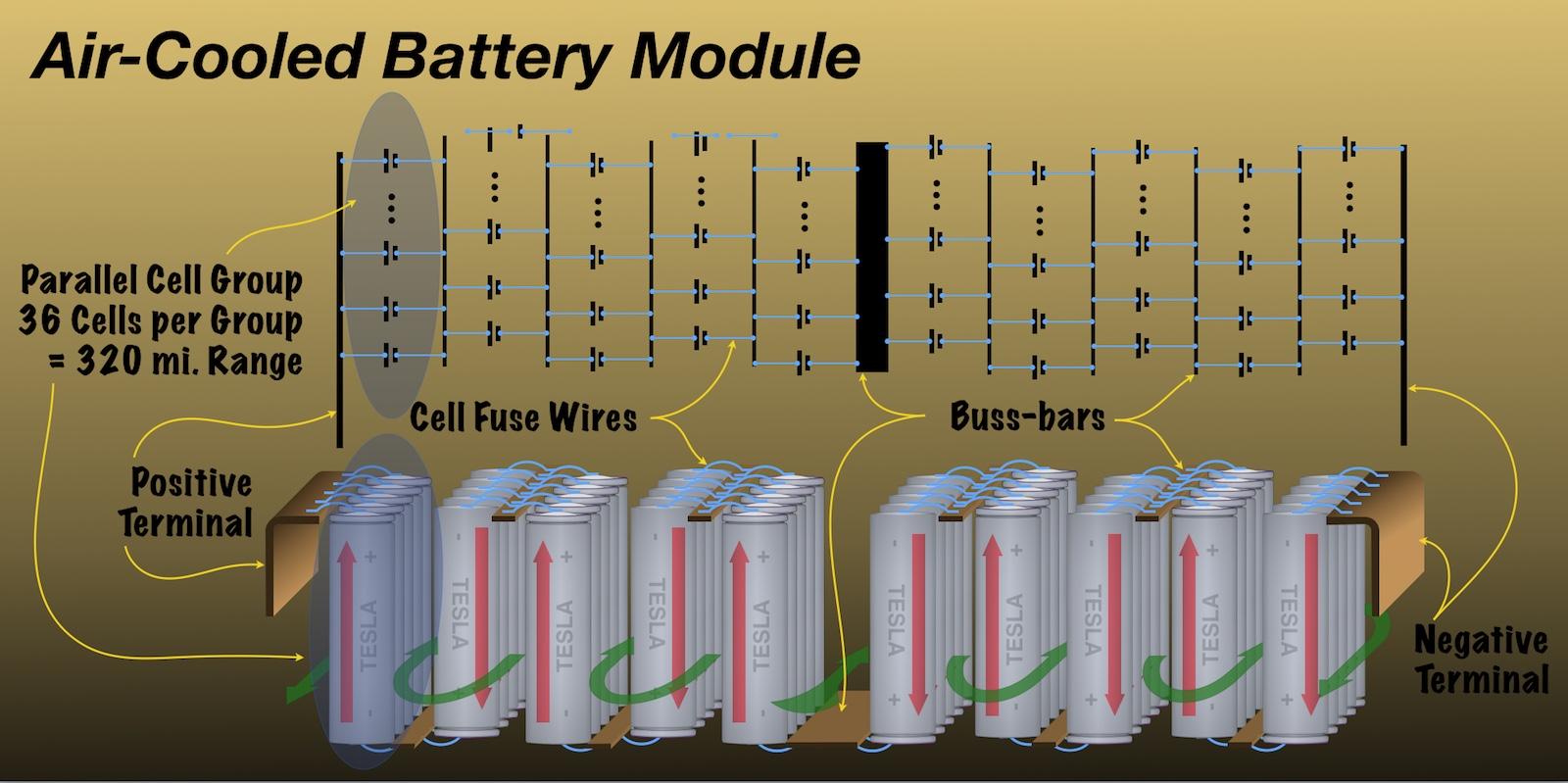
In the air-cooled battery module, groups of parallel connected cells are lined-up single file with air passages between cell groups. Buss-bars connecting cells in parallel are then placed above or below the air passages. - Author
There is a second, more significant advantage that comes with placing buss-bars beside rather than above/below the cells. It is that with buss-bars beside rather than above the cells, a single cell within the pack can be removed and replaced without having to break the wiring to all the other cells connected to a buss-bar.
Battery Packing:
The battery casing has to provide the mechanical and electrical interfaces to the product it is designed to power as well as to contain all the components outlined above. This is how the battery pack will be which is manufactured by the companies and employed in an Electric Vehicle.
REFERENCES:
https://datasheetspdf.com/pdf/1424845/A123Systems/ANR26650M1-B/1