Week-7 Challenge: DC Motor Control
DC MOTOR CONTROL
PART 1: AIM: Run MATLAB demo ‘Speed control of a DC motor using BJT H-bridge’.
OBJECTIVE: Modify the model such that armature current doesn’t shoot up when motor changes direction from forward to reverse.
Description of BJT H Bridge:
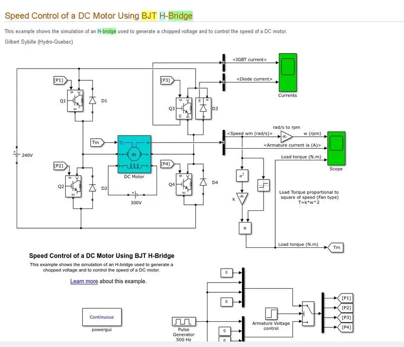
The Bipolar Junction Transistor (BJT) when used for power switching applications, operates as an IGBT. When it is conducting (BJT operating in the saturated region), a forward voltage Vf is developed between collector and emitter (in the range of 1 V). Therefore, the IGBT block can be used to model the BJT device.
The IGBT block does not simulate the gate current controlling the BJT or IGBT. The switch is controlled by a Simulink® signal (1/0). The DC motor uses the preset model (5 HP 24V 1750 rpm). It simulates a fan type load (where Load torque is proportional to square of speed). The armature mean voltage can be varied from 0 to 240 V when the duty cycle (specified in the Pulse Generator block) is varied from 0 to 100%.
The H-bridge consists of four BJT/Diode pairs (BJT simulated by IGBT models). Two transistors are switched simultaneously: Q1 and Q4 or Q2 and Q3. When Q1 and Q4 are fired, a positive voltage is applied to the motor and diodes D2-D3 operate as free-wheeling diodes when Q1 and Q4 are switched off. When Q2 and Q3 are fired, a negative voltage is applied to the motor and diodes D1-D4 operate as free-wheeling diodes when Q2 and Q3 are switched off.
BJT H BRIDGE MODEL:
Simulation Results with duty cycle 75% where 'Scope' shows motor speed, armature current and load torque and 'Currents' shows currents flowing in BJT Q3 and diode D3:
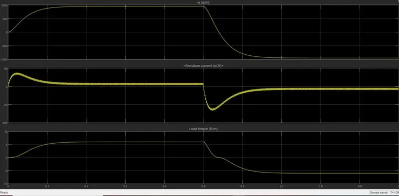
From the simulation results the motor starts in the positive direction with a duty cycle of 75% (mean DC voltage of 180V). At t= 0.5 sec., the armature voltage is suddenly reversed and the motor runs in the negative direction. when the motor runs in reverse direction the armature current shoots up highly this can be controlled by reducing the duty cycle . If we reduce the duty cycle the reverse voltage appearing across the motor decreases which inturn reduces the sudden shoot up of armature currrent.
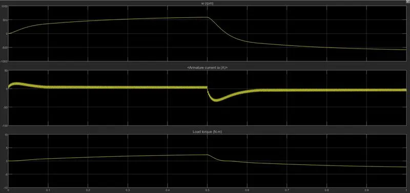
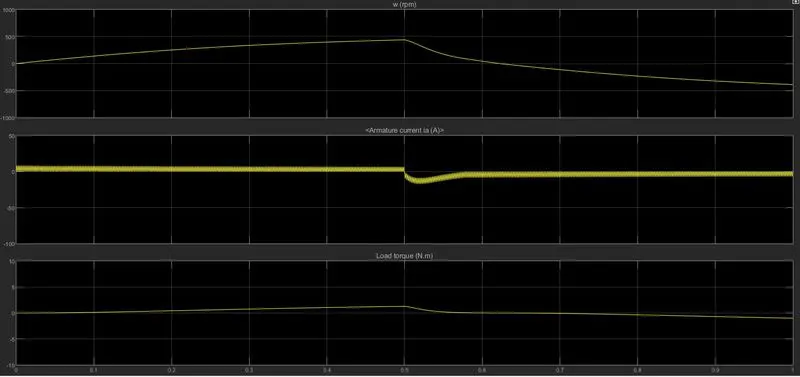
Duty cycle can be reduced to the desired level by changing the pulse width from pulse generator block.
simulation result with duty cycle 60% (144v):
simulation result with duty cycle 50% (120v):
Change in the IGBT & DIODE currents with the reduction in duty cycle:
WITH DUTY CYCLE 60%
WITH DUTY CYCLE 50%
CONCLUSION: when the motor runs in reverse direction the armature current shoots up highly this can be controlled by reducing the duty cycle . If we reduce the duty cycle the reverse voltage appearing across the motor decreases which inturn reduces the sudden shoot up of armature currrent.
PART 2:AIM :Refer the help section of ‘The Four-Quadrant Chopper DC Drive (DC7) block’.
OBJECTIVE: Compare ‘The Four-Quadrant Chopper DC Drive (DC7) block’. with H-bridge model.
SOLUTION:
The Four-Quadrant Chopper DC Drive (DC7) block:
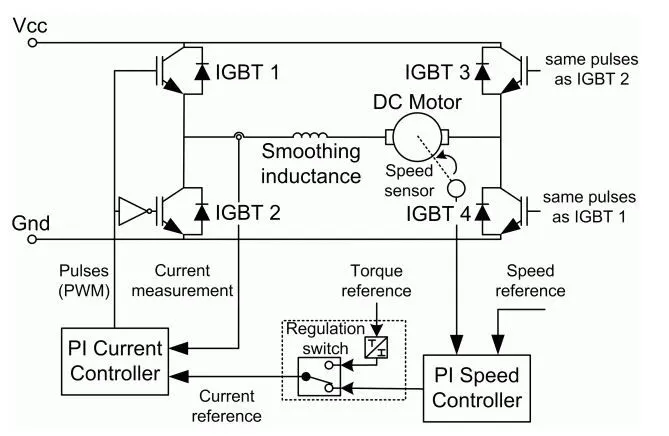
The Four-Quadrant Chopper DC Drive (DC7) block represents a four-quadrant, DC-supplied, chopper (or DC-DC PWM converter) drive for DC motors. This drive features closed-loop speed control with four-quadrant operation. The speed control loop outputs the reference armature current of the machine. Using a PI current controller, the chopper duty cycle corresponding to the commanded armature current is derived. This duty cycle is then compared with a sawtooth carrier signal to obtain the required PWM signals for the chopper.
The main advantage of this drive, compared with other DC drives, is that it can operate in all four quadrants (forward motoring, reverse regeneration, reverse motoring, and forward regeneration). In addition, due to the use of high switching frequency DC-DC converters, a lower armature current ripple (compared with thyristor-based DC drives) is obtained. However, four switching devices are required, which increases the complexity of the drive system.
The machine is separately excited with a constant DC field voltage source. There is thus no field voltage control. By default, the field current is set to its steady-state value when a simulation is started.
The armature voltage is provided by an IGBT converter controlled by two PI regulators. The converter is fed by a constant DC voltage source. Armature current oscillations are reduced by a smoothing inductance connected in series with the armature circuit.
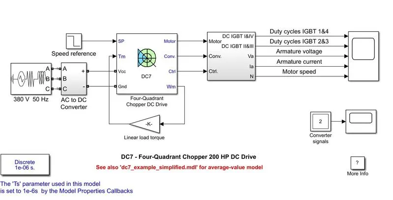
The Four-Quadrant Chopper WITH 200 HP DC Drive (DC7):
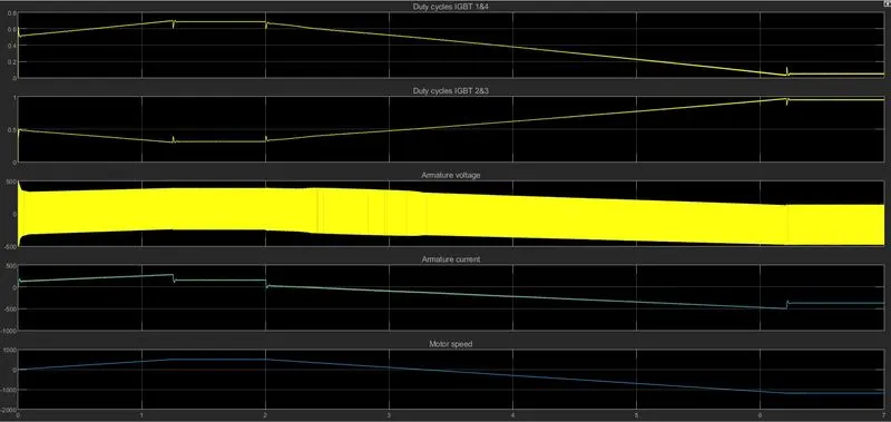
SIMULATION RESULT:
H-bridge model:
Simplified H Bridge model
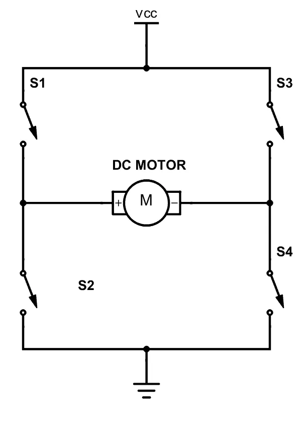
An H-bridge is a simple circuit that lets you control a DC motor to go backward or forward.You normally use it with a microcontroller to control motors. When you can control two motors to go either forward or backward
Circuit Operation:
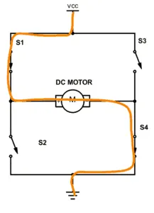
A DC motor spins either backward or forward, depending on how you connect the plus and the minus. If you close switch 1 and 4, you have plus connected to the left side of the motor and minus to the other side. And the motor will start spinning in one direction.
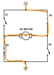
If you instead close switch 2 and 3, you have plus connected to the right side and minus to the left side. And the motor spins in the opposite direction.
CONCLUSION: A four quadrant chopper is a chopper which can operated in all the four quadrants. The power can flow either from source to load or load to source in this chopper. In first quadrant, a Class-E chopper acts as a Step-down chopper whereas in second quadrant it behaves as a Step-up chopper. This type of chopper is also known as Class-E or Type-E chopper where as The H Bridge Model is a simple circuit that lets you control a DC motor to go backward or forward.You normally use it with a microcontroller to control motors.
PART 3 : AIM & OBJECTIVE : To Make a suitable EV model using DC7 block and make result report.
SOLUTION:
DC7 four Quadrant chopper DC drive model converted to EV vehicle application:
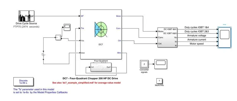
Changes made acccording to the EV vehicle application is explained below
STEP 1: DC voltage source should replace the Input voltage source of 380v 50hz and the rectifier also to be removed and to measure the battery current a current sensor is connected in series with the dc source.
STEP 2: A drive cycle source is given as input for the vehicle which should replace the speed reference block .
STEP 3: The linear torque block is removed and inplace of that a new subsystem is created with torque equation implemented giving speed as input and torque as output connected.
T = 24.7 + 0.0051 w^2
STEP4: Kept all the other parameters same and result obtained after simulation .
Simulation result:
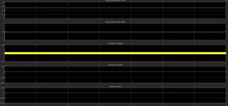
CONCLUSION: The output of the simulation result depends on the drive cycle input data .Trying with different drive cycle (speed vs time) values the corresponding changes in the armature voltage, armature current is observed.
PART 4 : AIM & OBJECTIVE : Explain in a brief about operation of BLDC motor.
BLDC MOTOR AND ITS OPERATION:
A brushless DC motor (also known as a BLDC motor or BL motor) is an electronically commuted DC motor which does not have brushes. The controller provides pulses of current to the motor windings which control the speed and torque of the synchronous motor.
These types of motors are highly efficient in producing a large amount of torque over a vast speed range. In brushless motors, permanent magnets rotate around a fixed armature and overcome the problem of connecting current to the armature. Commutation with electronics has a large scope of capabilities and flexibility. They are known for smooth operation and holding torque when stationary.
Before explaining the working of a brushless DC motor, it is better to understand the function of a brushed motor. In brushes motors, there are permanent magnets on the outside and a spinning armature which contains electromagnet is inside. These electromagnets create a magnetic field in the armature when the power is switched on and help to rotate the armature.
The brushes change the polarity of the pole to keep the rotation on of the armature. The basic working principle for the brushed DC motor and for brushless DC motor are same i.e. internal shaft position feedback.
Brushless DC motor has only two basic parts: rotor and the stator. The rotor is the rotating part and has rotor magnets whereas stator is the stationary part and contains stator windings. In BLDC permanent magnets are attached in the rotor and move the electromagnets to the stator. With brushless machines, the rotor includes two or more permanent magnets that generate a DC magnetic field. In turn, this magnetic field enters the stator core (a core made up of thin, stacked laminations) and interacts with currents flowing within the windings to produce a torque interaction between the rotor and stator. As the rotor rotates, it is necessary that the magnitude and polarity of the stator currents be continuously varied – and in just the right way - such that the torque remains constant and the conversion of electrical to mechanical energy is optimally efficient.