Week - 4
AUTOMATIC WASHING MACHINE & GEAR CHANGE IN A VEHICLE IS OPERATED & CONTROLLED BY IMPLEMENTING CONTROL LOGIC USING MATLAB SIMULINK STATEFLOW .
PART 1
Aim: control logic of a “washing machine” using Stateflow Implement as per given sequence.
Objective: Based on the input conditions of power supply & water availability various stages or states being changed while an automatic washing washing the clothes is being implemented from start to end by implementing control logic through matlab Simulink state flow arrangement by following the given conditions below stated:
- If the power supply is available, the system gets activated
- If the Water supply is not available, stop the process & indicate through LED
- Soaking time should be 200s followed by Washing time of 100s.
- Then rinsing happens for next 20s & dryer runs for 50s
After all the processes have completed turn on the finished LED
Procedure in designing state flow chart:
Taking a blank Simulink document a Simulink block called CHART is used to design the flowchart .so, inside of the CHART the flow chart is designed as per the input , system operating conditions & output. The detailed procedure in design & implementing the control logic to get the required output is shown below
Structure of control logic:
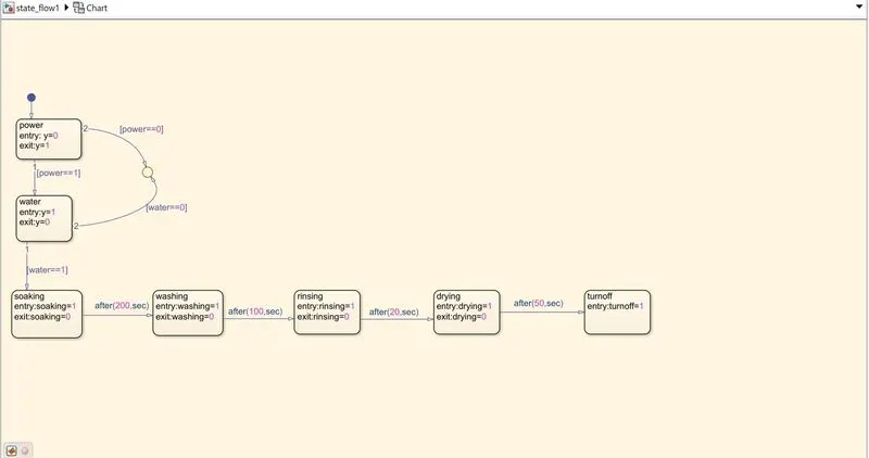
From the flow chart the inputs are defined as power & water, outputs are defined as Y,soaking,washing,rinsing,drying,turnoff.
Entry & exit are actions based on that the lights are displayed with red & green colours for 1,0 control logic. The loops/arrow indication from one block to another are the conditions that the system checks before proceeding to the next stage.
1 represents ON condition & 0 represents OFF condition.
Both power & water are required to start the process so,both the switches to be turned ON.
All the six outputs are connected to the display blocks where lamps are assigned to all the output display blocks which displays red and green colours for logical input & output conditions. After assigning all the input & output blocks in the symbol pane the simulation gets started.
As the logic of 1 & 0 enters in to each stage the system checks for condition if the condition satisfied the process is further forwarded and finally completes the end operation. But, if the system doesnot satisfy the condition the state of action is either diverted or wil be stoping at the before state where the condition is satisfied and always checks for the next input .
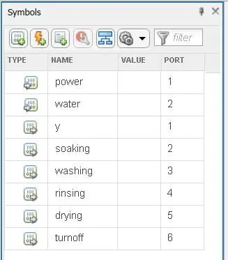
Symbol pane: Here we have to define the variables which are used in the flow chart like input & output etc., to further implement and start the simulation with out assigning the variables used the simulation cant be performed.
Simulink blocks used:
1)constant
2)lamp
3)switch
4)display
Logic checked with power off(0)& water off (0):
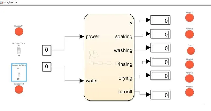
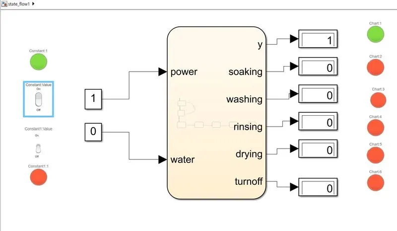
Logic checked with power on (1)& water off (0):
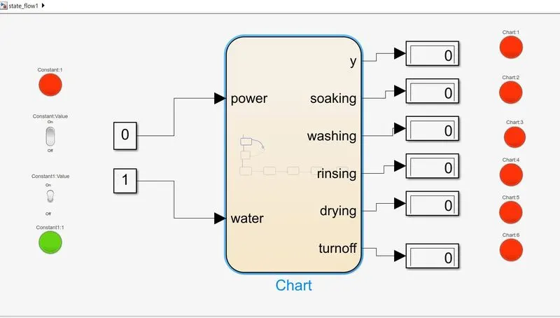
Logic checked with power off (0)& water on(1):
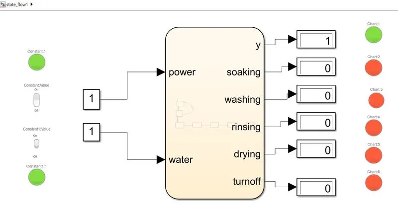
Operation of washing machine Logic checked with power on (1)& water on(1), checked with all conditions to attain the objective:
Step 1: checking for power and water & showing a display as Y OUPUT
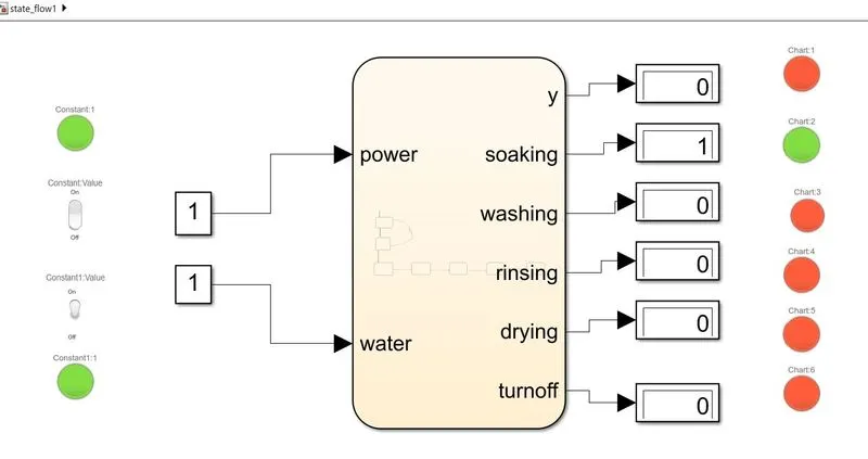
Step 2 soaking state:
Step 3 washing state:
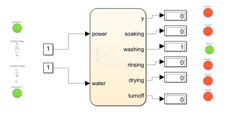
Step 4 rinsing state:
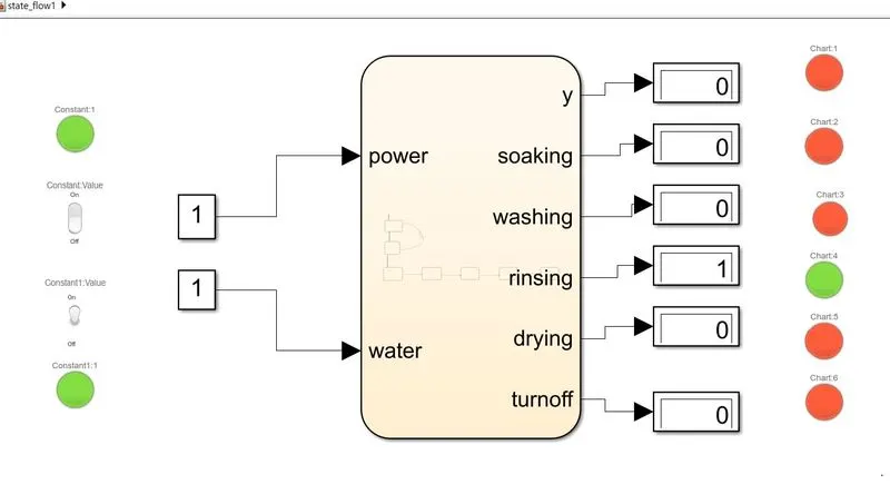
Step 5 drying state:
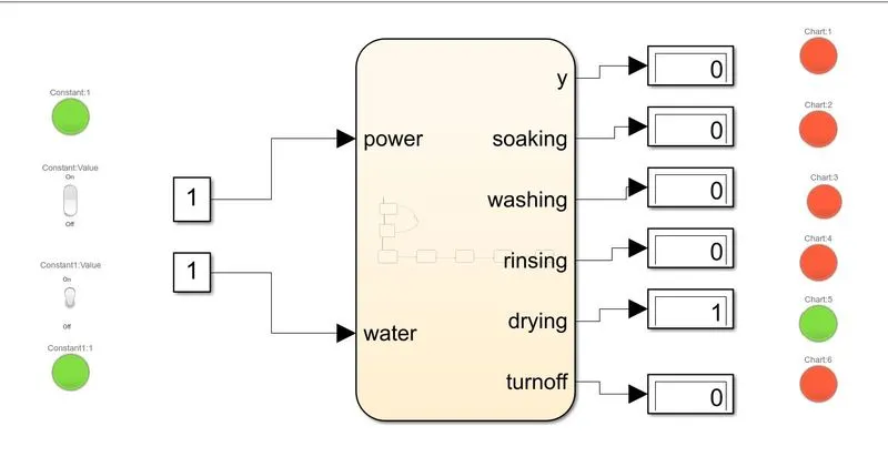
Step 6 process end washing machine turn off:
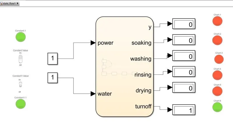
Debugging process:
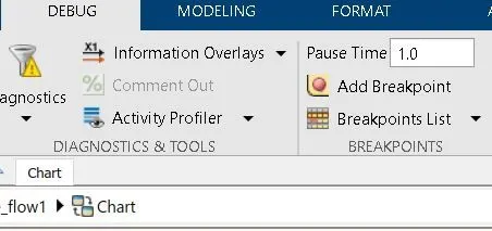
debugging used in the state flow to go inside of the flow chart where the state transition can be visualised from start to end of the logic with all conditions satisfied for that a breakpoint to be created before starting the simulation.
Conclusion: Finally the aim & objective of automatic operation of washing machine is proved by implementing the control logic with the help of matlab simulink stateflow arrangement.
PART 2
AIM: TO Make a Simulink chart for the “Gear shift” logic.
Objective:The logic to be proved as per below conditions:
Speed Range(kmph) Gear
0 to 15 1
16 to 25 2
26 to 40 3
41 to 60 4
Above 61 5
Give speed input while the simulation is running & display the gear number.
Procedure in designing state flow chart:
Taking a blank Simulink document a Simulink block called CHART is used to design the flowchart .so, inside of the CHART the flow chart is designed as per the input , system operating conditions & output. The detailed procedure in design & implementing the control logic to get the required output is shown below
Structure of control logic:
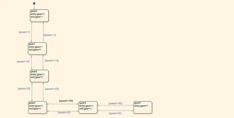
From the flow chart the inputs are taken as speed and the output is the gear position according to the speed. Here the input is given with a constant value between the speeds 0 to 61 testing at each state by using a condition with an arrow mark for the right gear to be operated w.r.t assigned speed values.
A display block is used to output the values of gear position.
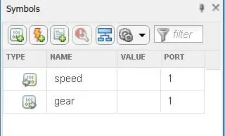
In the symbol pane the input and output variables are assigned before starting the simulation and if it is accepted by the system then the simulation can start with giving giving different speed values to output a proper gear at each particular speed to satisfy the condition.
symbol pane:
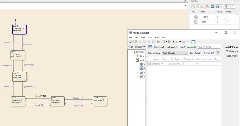
Output gear '0' position with speed '0' input:
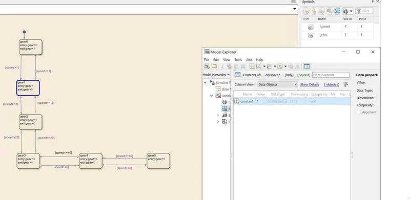
Output gear '1' position with speed '7' input :
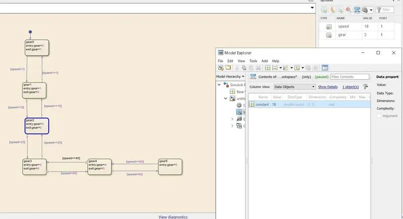
Output gear '2' position with speed '18' input :
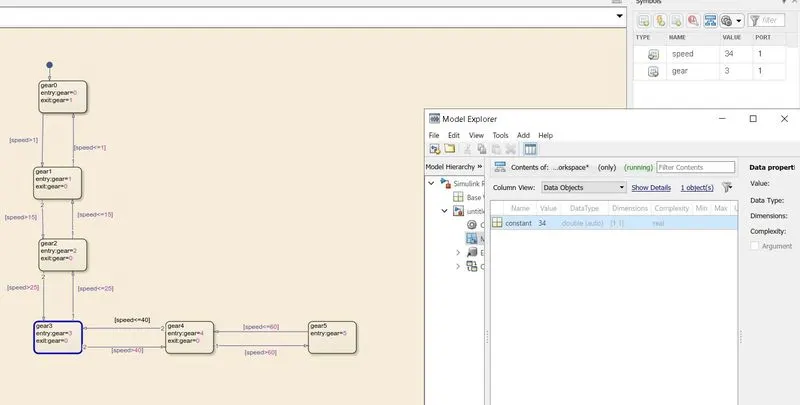
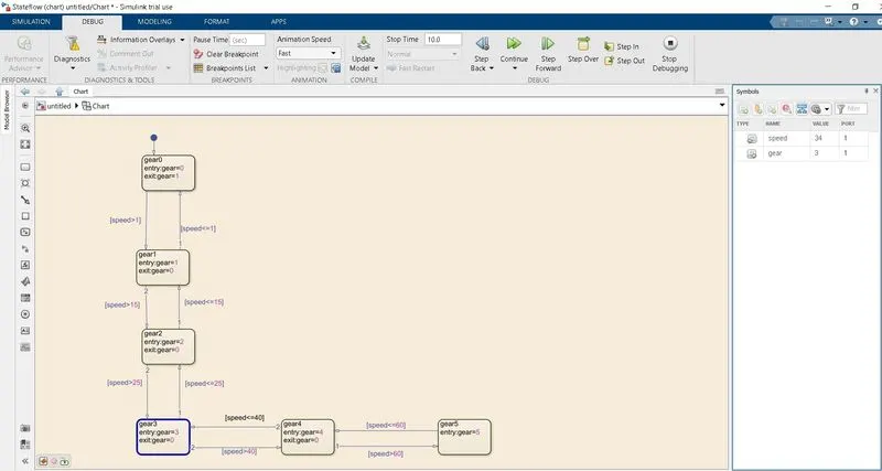
Output gear '3' position with speed '34' input :
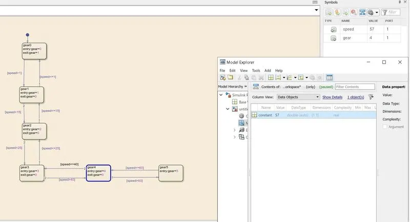
Output gear '4' position with speed '57' input:
Output gear '5' position with speed '75' input :
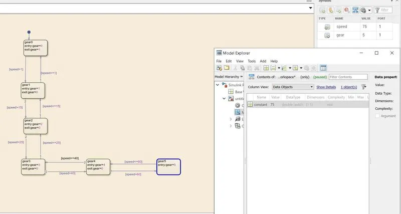
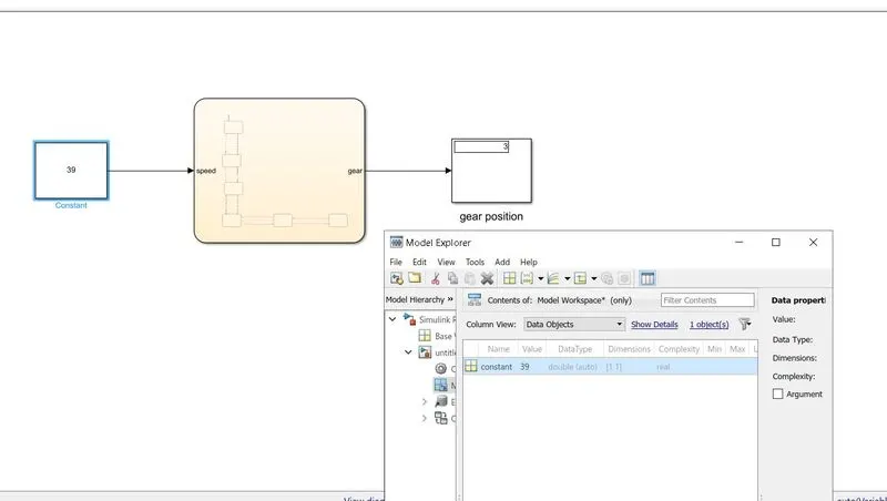
All the above conditions of input and output in the debugging process is shown simultaneously with constant is created as a variable in the model workspace.
output shown inside the flow chart while debugging with input speed 34 showing an output of gear 3
Output shown with display where Input speed 39 showing an output gear position of 3. In the same process coming out of debugging and the input speed w.r.t output gear position can be tested to get the required gear indication with dispaly.
Conclusion: In this manner a simulink chart is prepared for gear shift logic implementation using matlab simulink stateflow arrangement.