Week -2
PART 1
AIM : To Make or design a Simulink model of doorbell using solenoid block.
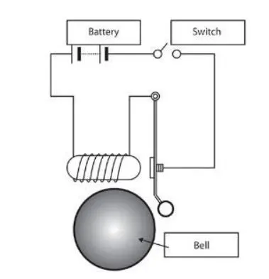
OBJECTIVE : Create a situation where the switch is closed for 2 seconds and then released. Observe the physical movement of the plunger. In the doorbell arrangement, when the switch is closed the electromagnet receives electrical power from the battery and pulls the metal arm to hit the bell producing sound. Assume remaining parameters.
CONTENT OF DESIGN :
SOLENOID : solenoid is an electro mechanical device which takes electrical input and produces mechanical output. Construction wise solenoid is an electromagnet which is used in many applications like door bell and solenoid valve when we require a mechanical output we place some metals near to the solenoid. so, when this solenoid is energised by electrical input the metals near to the solenoid gets attracted towards it and released when the solenoid is de energised after the electrical input is withdrawn. Here a motion or movement is observed by the metals because of the solenoid .so, this working principle is used in different applications.
APPLICATION : One of the important application of solenoid in many ships where solenoid valve in connection with hydraulic system is used to open the sea chest valves which are positioned at the bottom of the ships . Solenoid valves are simple and effective electrically operated valves to control liquid, gas or steam. Solenoid valves have many uses, from controlling compressed air to operate pneumatic equipment, controlling high-pressure oil to operate hydraulic equipment.
REQUIREMENTS FOR DESIGNING THE SIMULINK MODEL :
1)SOFTWARE TOOLS
Matlab is a programming language used to compute the simulating results in the background.
Simulink is a graphical user interface, virtual environment and fictitious setup . simulink is a block diagram environment instead of using equations which makes easy for the user to design a model for a specific application and to test it to see when it actually behaves in real life situation is called simulation. Simulink library offers plenty of blocks usefull for modelling complex systems. Simulink provides us blocks which can represent A)Entire physical system OR Sub systems B)Signals OR Mathematical functions.
Simscape provides us models of physical systems of both mechanical and electrical domains to rapidly create models for different applications can be tested with the help of Simulink.
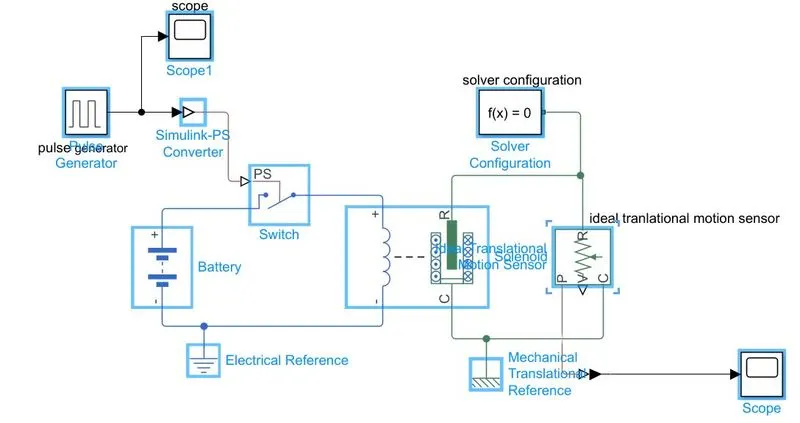
2)BLOCKS REQUIRED WHICH ARE EXTRACTED FROM SIMULINK & SIMSCAPE LIBRARY
- A) Battery : A DC voltage source required to energise the solenoid.
- B) Solenoid : Required for giving mechanical output to ring the bell.
- C) Switch : To control the bell to make it on or off.
- D) Pulse Generator: Is given as an input signal for the switch and also to control the on and off time for ringing the bell for a particular time period in seconds . Generally pulse generator is an electronic circuit which generates pulse signal by which the required circuit is triggered internally or externally. By providing necessary input parameters A) pulse repetition rate B) frequency C) pulse width D) time delay can be controlled by using pulse generator.
- E) Scope : scope provides several methods for displaying simulation data. The scope block displays its input with respect to the simulation time it allows you to adjust the amount of time and the range of input values displayed.
- F) Ideal translational motion sensor : Used to measure the physical signal of velocity(V) and position(P) consists of 4 connections namely R, C, V & P. connections R & C are mechanical translational conserving ports connects the sensor input with mechanical output & C as a common reference.
- G) Simulink to physical system converter (s – ps conveter) : Block used to connect the Simulink block to a physical system (Sims cape) block which is used in between as a converter.
- H) Physical system to Simulink converter (ps – s converter) : Block used to connect the physical system (Sims cape) block with Simulink block which is used in between as a converter.
- I) Solver configuration (S.C) : All the Sims cape blocks connected together represents a physical network this is called a model. This model represents a set of ordinary differential equations which is solved by applying numerical computational method by a SOLVER our (S.C) block provides parameters for the SOLVER that our model needs before the simulation starts.so finally the physical network or model requires solver settings information for simulation.
Each simscape block diagram requires a (S.C) block because the block represents a set of ordinary differential equations which is solved by using numerical method by a Solver. Through its computation , it determines the time of the next simulation step. (S.C) block provides the parameters for the solver that the model needs before the simulation gets started.
(S.C) block does not represent a physical part unlike the other simscape blocks like motors etc., in the overall system. A connected simscape block diagram represents a physical network this physical network requires solver settings information for simulation.
- J) Electrical reference : This block represents the model contains some electrical elements. A model with electrical elements must contain at least one electrical reference block . It represents an electrical ground. Electrical conserving ports of all the blocks that are directly connected to ground must be connected to an electrical reference block.
- K) Mechanical translational reference : The Mechanical Translational Reference blockrepresents a referencepoint, or frame, for all mechanical translational All translational ports that are rigidly clamped to the frame (ground) must be connected to a Mechanical Translational Reference block.
DESIGN PROCEDURE OF MODEL & CONNECTIONS :
INPUT PULSE SIGNAL :
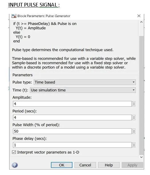
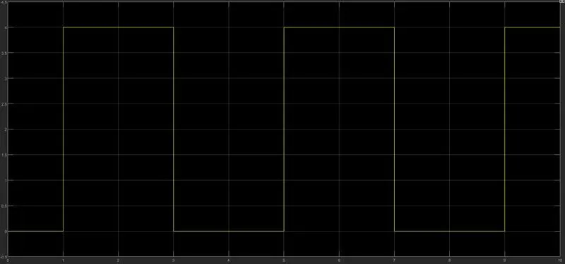
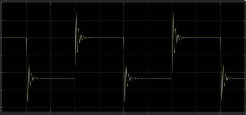
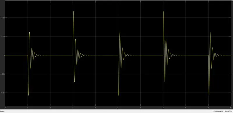
Output of pulse generator given as an input to the switch to get closed for 2 sec the time period of pulse is given 4 sec and the pulse width is 50 % of time period i.e 2 sec and then released.
Creating a situation where the switch is closed for 2 seconds and then released
OUTPUT POSITION :
OUTPUT VELOCITY :
CONCLUSION : The above model is one of the application of solenoid in a door bell arrangement which is designed virtually and analysed the output by using Mat lab Simulink .
PART 2
AIM : Use a thermistor to sense the temperature of a heater & turn on or turn off the fan.
OBJECTIVE : The Fan should be ON if the temperature above 25 °C, OFF otherwise Temperature source is 20 °C from 0 to 10 seconds, 27 °C from 10 to 30 seconds, 23 °C from 30 to 50 seconds. Here thermistor is the main element to sense the temperature based on the working and accuracy of it our objective is achieved.
CONTENT OF DESIGN :
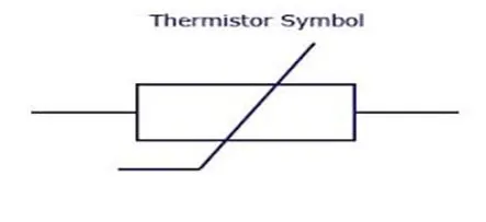
THERMISTOR : It is a thermal resistor unlike normal resistor and there are 2 basic types of thermistors names PTC & NTC.
(PTC) positive temperature coefficient means resistance value increases with increase in temperature. (NTC) negative temperature coefficient means resistance value decreases with increase in temperature.
APPLICATION : NTC type used as a temperature sensors used in fire alarms.
PTC type used for protecting devices and circuits which are installed in series with the circuits where the this type of resistor restricts high current flow in the circuit .
REQUIREMENTS FOR DESIGNING THE SIMULINK MODEL :
1)SOFTWARE TOOLS
Matlab is a programming language used to compute the simulating results in the background.
Simulink is a graphical user interface, virtual environment and fictitious setup. simulink is a block diagram environment instead of using equations which makes easy for the user to design a model for a specific application and to test it to see when it actually behaves in real life situation is called simulation. Simulink library offers plenty of blocks usefull for modelling complex systems. Simulink provides us blocks which can represent A) Entire physical system OR Sub systems B) Signals OR Mathematical functions.
Simscape provides us models of physical systems of both mechanical and electrical domains to rapidly create models for different applications can be tested with the help of Simulink.
2)BLOCKS REQUIRED WHICH ARE EXTRACTED FROM SIMULINK & SIMSCAPE LIBRARY
- A) Input signal from signal builder block : using this block we can design and modify the time vs temperature signal or any signal as per the our requirement.
B)Controlled temperature source : this block maintains temperature differences at specified time periods using the source which as given as an input to the thermistor.
C)Thermistor : NTC type used.
D)Current sensor : used to sense the current output.
E)Resistor : used as a protecting device in the circuit which is of PTC type.
F)Dc motor : here the electrical input is converted to mechanical output used to create a
fan or dc motor represents a fan in this ckt.
D)Battery : used to give supply to the circuit.
E)Voltage sensor : used to sense the voltage output.
F)Voltage source : used to connect the motor with current output.
G)Switch : used as a controlling device .
H)Mechanical rotational motion sensor : used to sense the mechanical rotation and gives corresponding output in the form of velocity and position.
I)Scope : scope provides several methods for displaying simulation data. The scope block displays its input with respect to the simulation time it allows you to adjust the amount of time and the range of input values displayed.
J)Display : used to display the current output in numerical values.
K)Constant : used to represent switch on & off states.
L)Solver configuration block : All the Sims cape blocks connected together represents a physical network this is called a model. This model represents a set of ordinary differential equations which is solved by applying numerical computational method by a SOLVER our (S.C) block provides parameters for the SOLVER that our model needs before the simulation starts.so finally the physical network or model requires solver settings information for simulation.
Each simscape block diagram requires a (S.C) block because the block represents a set of ordinary differential equations which is solved by using numerical method by a Solver. Through its computation , it determines the time of the next simulation step. (S.C) block provides the parameters for the solver that the model needs before the simulation gets started.
(S.C) block does not represent a physical part unlike the other simscape blocks like motors etc., in the overall system. A connected simscape block diagram represents a physical network this physical network requires solver settings information for simulation.
M)Mechanical rotational reference : used to connect to mechanical sources and elements.
N)Electrical reference : This block represents the model contains some electrical elements. A model with electrical elements must contain at least one electrical reference block . It represents an electrical ground. Electrical conserving ports of all the blocks that are directly connected to ground must be connected to an electrical reference block.
O)Thermal reference : connected to thermal Simulink block
P)Simulink – PS & PS –Simulink converter : Block used to connect the Simulink block to a physical system (Sims cape) block which is used in between as a converter.
Block used to connect the physical system (Sims cape) block with Simulink block which is used in between as a converter.
DESIGN PROCEDURE OF MODEL & CONNECTIONS :
Part 1 circuit with out a motor connection :
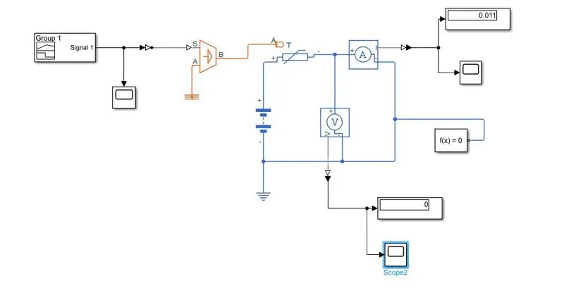
Current output w.r.t input signal time vs temperature
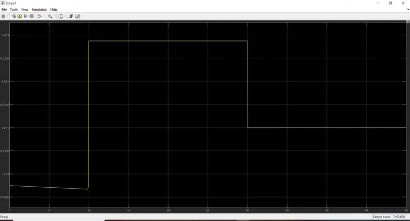
Part 2 circuit with resistor involved

Thermistor input signal designed from signal buider block and given as an input to controlled voltage source
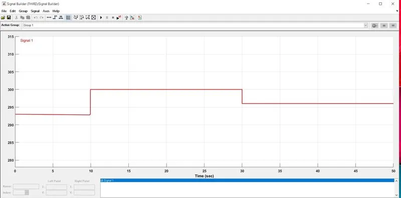
Complete design of thermistor model to control the fan at specific time period :
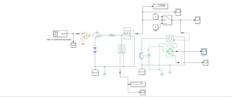
Output 1 of velocity
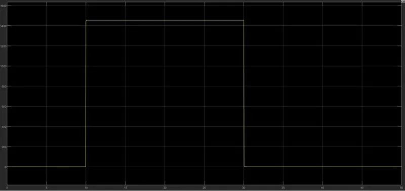
Output 2 of position
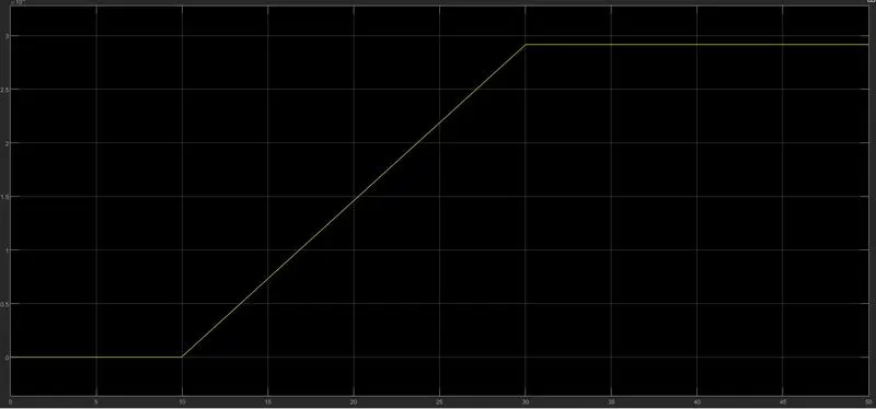
Conclusion :
The objective of controlling the fan at specified time period is achieved by using a thermistor as the main element in the circuit. In the same process any circuit model can be designed where thermistor is used as a protecting element w. r.t temperature variations in the circuit.