Project-1: Powertrain for aircraft in runways
Project-1: Powertrain for aircraft in runways
PART 1 : Search and list out the total weight of various types of aircrafts.
SOLUTION:
Types Of Aircraft
There are a number of ways to identify aircraft by type. The primary distinction is between those that are lighter than air and those that are heavier than air.
Lighter-than-air
Aircraft such as ballons nonrigid airships(blimps), and dirigibles are designed to contain within their structure a sufficient volume that, when filled with a gas lighter than air (heated air, hydrogen, or helium), displaces the surrounding ambient air and floats, just as a cork does on the water. Balloons are not steerable and drift with the wind. Nonrigid airships, which have enjoyed a rebirth of use and interest, do not have a rigid structure but have a defined aerodynamic shape, which contains cells filled with the lifting agent. They have a source of propulsion and can be controlled in all three axes of flight Dirigibles are no longer in use, but they were lighter-than-air craft with a rigid internal structure, which was usually very large, and they were capable of relatively high speeds. It proved impossible to construct dirigibles of sufficient strength to withstand routine operation under all weather conditions, and most suffered disaster, either breaking up in a storm, as with the U.S. craft Shenandoah, Akron, and Macon, or through ignition of the hydrogen, as with the Hindenburg in 1937.

Airship
HEAVIER THAN AIR
This type of aircraft must have a power source to provide the thrust necessary to obtain lift. Simple heavier-than-air craft include kites These are usually a flat-surfaced structure, often with a stabilizing “tail,” attached by a bridle to a string that is held in place on the ground. Lift is provided by the reaction of the string-restrained surface to the wind.
Another type of unmanned aircraft is the unmanned aerial vehicle(UAV), commonly called drones or sometimes remotely piloted vehicles (RPVs). These aircraft are radio-controlled from the air or the ground and are used for scientific and military purposes.
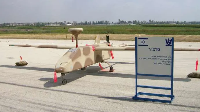
unmanned aerial vehicle
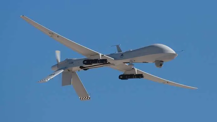
unmanned aerial vehicle
Unpowered manned heavier-than-air vehicles must be launched to obtain lift. These include hang gliders gliders, and sailplanes.
Hang gliders are aircraft of various configurations in which the pilot is suspended beneath the (usually fabric) wing to provide stability and control. They are normally launched from a high point. In the hands of an experienced pilot, hang gliders are capable of soaring (using rising air columns to obtain upward gliding movement).
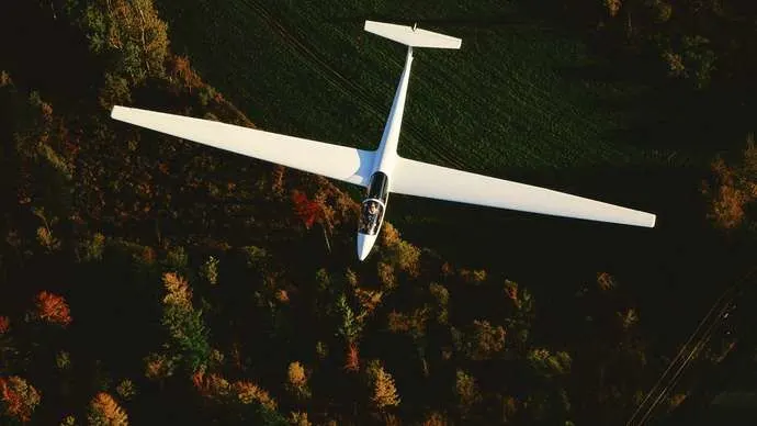
Gliders are usually used for flight training and have the capability to fly reasonable distances when they are catapulted or towed into the air, but they lack the dynamic sophistication of sailplanes These sophisticated unpowered craft have wings of unusually high aspect ratio (that is, a long wing span in proportion to wing width). Most sailplanes are towed to launch altitude, although some employ small, retractable auxilary engines. They are able to use thermals (currents more buoyant than the surrounding air, usually caused by higher temperature) and orographic lift to climb to higher altitude and to glide for great distances. Orographic lift results from the mechanical effect of wind blowing against a terrain feature such as a cliff. The force of the wind is deflected upward by the face of the terrain, resulting in a rising current of air.
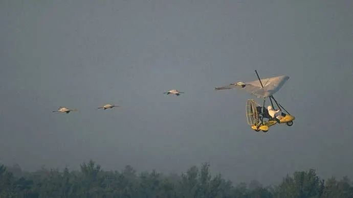
Ultralights which were originally merely hang gliders adapted for power by the installation of small engines similar to those used in chain saws, have matured into specially designed aircraft of very low weight and power but with flying qualities similar to conventional light aircraft. They are intended primarily for pleasure flying, although advanced models are now used for training, police patrol, and other work, including a proposed use in combat.
Civil aircraft
All nonmilitary planes are civil aircraft. These include private and business planes and commercial airliners.
Private aircraft are personal planes used for pleasure flying, often single-engine monoplanes with nonretractable landing gear. They can be very sophisticated, however, and may include such variants as: “warbirds,” ex-military planes flown for reasons of nostalgia ranging from primary trainers to large bombers; “homebuilts,” aircraft built from scratch or from kits by the owner and ranging from simple =adaptations of Piper Cubs to high-speed, streamlined four-passenger transports; antiques and classics, restored older aircraft flown, like the warbirds, for reasons of affection and nostalgia; and aerobatic planes, designed to be highly maneuverable and to perform in air shows.
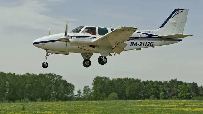
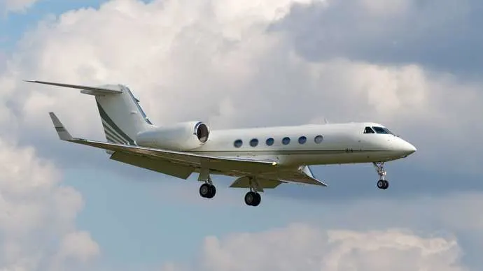
Business aircraft are used to generate revenues for their owners and include everything from small single-engine aircraft used for pilot training or to transport small packages over short distances to four-engine executive jets that can span continents and oceans. Business planes are used by salespeople, prospectors, farmers, doctors, missionaries, and many others. Their primary purpose is to make the best use of top executives’ time by freeing them from airline schedules and airport operations. They also serve as an executive perquisite and as a sophisticated inducement for potential customers. Other business aircraft include those used for agricultural operations, traffic reporting, forest-fire fighting, medical evacuation, pipeline surveillance, freight hauling, and many other applications. One unfortunate but rapidly expanding segment of the business aircraft population is that which employs aircraft illegally for transporting narcotics and other illicit drugs. A wide variety of similar aircraft are used for specialized purposes, like the investigation of thunderstorms, hurricane tracking, aerodynamic research and development, engine testing, high-altitude surveillance, advertising, and police work.
Airplanes
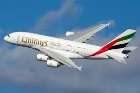
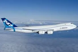
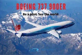
MTOW = Maximum take-off weight, MLW = Maximum landing weight, TOR = Take-off run LR = Landing run
|
Type |
MTOW [kg] |
MLW [tonnes] |
TOR [m] |
LR [m] |
||
|
640,000 |
591.7 |
3500 |
Heavy |
Super |
||
|
589,670 |
3660 |
Heavy |
Super |
|||
|
575,000 |
394 |
3100 |
1930 |
Super |
Super |
|
|
447,700 |
346.091 |
3100 |
1800 |
Heavy |
Heavy |
|
|
443,613 |
306.175 |
3100 |
Heavy |
Heavy |
||
|
412,770 |
295.742 |
3090 |
Heavy |
Heavy |
||
|
85,000 |
66.36 |
2500 |
1704 |
Medium |
Large |
|
|
85,000 |
71.35 |
2804 |
1829 |
Medium |
Large |
PART 2: Is there any difference between ground speed and air speed?
Solution:
Airspeed is the vector difference between the ground speed and the wind speed. On a perfectly still day, the airspeed is equal to the ground speed. But if the wind is blowing in the same direction that the aircraft is moving, the airspeed will be less than the ground speed.
What's the Difference Between Airspeed and Ground Speed?

Airspeed and ground speed are completely different when it comes to determining how fast an airplane flies.
Back in February 2019, a Virgin Atlantic Boeing 787 jet flying over Pennsylvania in route from Los Angeles to London reached what might seem like an amazing speed of 801 miles per hour (1,289 kilometers per hour), according to CBS News
But the speed record wasn't because that Virgin Atlantic aircraft itself was exceptionally fast. Like a sprinter running with the wind at his back, the aircraft benefited from an exceptionally fast jet strem, a high-speed wind moving at 231 miles per hour (371.7 kilometers per hour). It was the fastest jet strem in more than 60 years.
As CBS News explained, the result was that the 787 flew considerably faster than the aircraft's typical cruising speed of 561 miles per hour (902.8 kilometers per hour).
Therein lies the difference between airspeed and ground speed.
As this explainer on the NASA website details, ground speed is how fast an airplane is traveling, relative to a fixed point on the ground. Think of it this way: Ground speed is how fast an airplane's shadow would move across the land. If there's a strong wind pushing an aircraft, that's reflected in the ground speed.
Airspeed, in contrast, is how fast an airplane is really flying strictly under its own power, which is calculated by subtracting the wind speed from the ground speed: On a perfectly still day, the airspeed is equal to the ground speed. But if the wind is blowing in the same direction that the aircraft is moving, the airspeed will be less than the ground speed.
Airspeed doesn't just affect airplanes. It also affects our vehicles on the ground. As this study published in 2013 in the International Journal of Energy and Environmental Engineering describes, a car's airspeed on the highway is what really determines its fuel efficiency, rather than ground speed or the speedometer reading.
PART 3:Why is it not recommended to use aircraft engine power to move it on the ground at Airport?
Solution :
Aircraft Ground Running
DESCRIPTION
The term Aircraft Ground Running is usually used to describe the operation of some or all of the engines of an aircraft, whilst on the ground, for the purpose of functionally checking the operation of either engines or aircraft systems. This usually takes place prior to the release to service of an aircraft from maintenance. Ground running may be carried out either prior to, during or after the rectification of a defect or scheduled work on an engine or an aircraft system, when this requires engines to be operating in order to assess its function. Although the aircraft may need to be taxied or towed to an approved ground running position under a clearencefrom ATC most operators and maintenance organisations do not require pilots to be on board because aircraft technicians can be trained and approved for these duties.
The Risk to Operational Safety
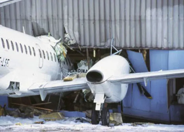
The risks which may arise from engine ground running relate to the potential for loss of control of the aircraft by those persons occupying the pilot seats in the flight deck. In most cases, such persons will be maintenance personnel holding specific company-issued approval for the required tasks. The consequences of loss of control during taxi or towing are the same as apply to these operations generally and this article is concerned only with the risks arising from the static running of one or more aircraft engines. Unwanted consequences from such static running are mainly related to those arising from the unintended movement of the aircraft during engine running - effectively a loss of control - especially during high power engine running. Damage can occur to the aircraft itself, other aircraft nearby or to airside structures. In addition, there is a risk of injury to ground support personnel who may be in relatively close proximity to the aircraft.
Overall Risk Mitigation
The best form of overall mitigation is to ensure that all persons authorised to supervise or directly participate in engine ground running from the flight deck, who are not pilots or flight engineers currently rated on the specific aircraft type, are in receipt of suitable initial training and that there is a proper system for both initial and recurrent qualification for engine ground running duties. Both initial and recurrent qualification must include practical training and assessment of task competence using either a full flight simulator or an aircraft. Between formal competency assessments, a maximum interval between performance of the qualified task should be specified. If that interval is exceeded, the qualification would become void until remedial action has been competed. In this respect, the task of engine ground running should be seen as part of a broader group of aircraft ground movement tasks which can be carried out under the control of flight deck occupants other than type rated flight crew.
Generic and type specific knowledge requirements and practical experience related to ground engine runs defined in regulations (i.e. in Europe EASA Part 66 Appendix I (Basic Training Requirements) and Appendix III (Type Training Requirements), AMC 66 Appendix II (Aircraft type practical experience list of tasks)) have to be met by the license holders. Only certifying staff, whose competency has been assessed by the Quality Department of the Approved Maintenance Organisation (i.e. Part 145 Approved Organisation in Europe), can / should be issued with “certification authorisation” to conduct ground engine runs. Although the regulations do not stipulate, some organisations use simulators for training their engineers whilst others prefer on-the-job training and expect engineers to carry out engine runs under supervision before they are given the authorisation. All certifying staff must follow the up-to-date ground engine run procedures, which are defined in the applicable aircraft maintenance manual as well as the Maintenance Organisation Exposition, which may include additional specific requirements applicable to the organisation. (Ref: AMC.145.A.70)
Key proactive components for safe task completion are clear procedural guidance and a series of checklists for use during each stage of a ground running task. Standard Checklists, which should be specific to the non-airborne limitation and so cannot just be the flight crew versions, should include:
- Pre start
- Starting
- After Start (engine ground idle running only)
- After Start (engine running above ground idle)
- Pre Taxi
- Pre Towing
- Pre Engine Running above Flight Idle (unless this action occurs immediately after engine start.)
In addition, response to potential but unexpected occurrences must be covered by appropriate training and, where a rapid response may be necessary, memory actions.
Finally, engine ground running, especially if engine operation above Ground Idle is to take place, is best carried out with both flight deck pilot seats occupied and with clearly defined roles for the person in charge and their assistant. In particular, this allows checklists to be carried out using the challenge and response method.
Task Detail - Key Risk Controls
- Thrust levels above ground idle should be applied symmetrically.
- Task Checklists must be constructed so that there is never a cause to temporarily defer items and continue.
- Once a task has been initially briefed by the person authorised to supervise it, modifications to the briefed task should only be permitted within a clearly defined limit without a complete task re-briefing.
- Where two persons, both holding the necessary authorisation to be able to supervise a task, are teamed together to conduct it, one of them must be designated by the Aircraft Operator or MRO as the supervisor for a particular task and should lead the pre-task briefing. No change of designated supervisor should occur during a briefed task.
- Any plan for engine ground running which is authorised for power above Ground Idle must be carried out with the aircraft in a position in which unexpected and unintended forward movement will not result in damage or injury should the appropriate response from the designated supervisor be delayed.
- Knowledge of the brake and hydraulic systems on any aircraft type for which a person is permitted to occupy a flight deck seat, for the purposes of engine ground running, must be comprehensive and formally certified as such.
- All equipment and personnel must be completely clear of an aircraft before engine running above ground idle occurs.
- Where local regulations require that contact with ATC GND is maintained in connection with ground running, this should specifically include ensuring that ATC are advised prior to commencing or after completing any periods of ground running at power above ground idle, even if such activity does not require explicit ATC permission at the site being used.
- Where engines are being run for the purposes of facilitating system tests, a specific test sequence should be pre-specified in text form and should incorporate any appropriate checklists or give specific AMM references to these. If the latter method is used, current copies of such checklists should be appended to the test sequence.
- Wheel chocks should be in place at the main landing gear for all ground running. In the case of ground running of engines above ground idle, care should be given to checking that the chocks being used are of a type which corresponds to the mass of the aircraft involved and that the chocking of wheels other than those at the main landing gear assemblies is considered.
- AMM’s require that a fire extinguisher be within the vicinity of the engine, particularly if the engine cowlings are open and you are going to do leak check. This is because, in the case of a fire due to an oil/fuel leak in the fan section, the engine fire extinguishers may not be not be effective and you have to fight the fire with an external fire extinguisher.
- QA audits carried out by the Aircraft Operator and any MRO involved should include a compliance audit of all procedures associated with engine ground running. This must extend to the recorded application of relevant procedures as well as their formal documentation.
Incident Investigation
Although non-injury engine ground running incidents will not normally be subject to investigation under Annex 13 procedures, it is important that, to facilitate any necessary modification to future risk management, all serious incidents are subject to the same standard of independent investigation as would apply to an event occurring when the aircraft was released to service and under the control of qualified flight crew.
Accidents and Incidents
B762, Los Angeles USA, 2006(On June 2, 2006, an American Airlines Boeing 767-200ER fitted GE CF6-80A engines experienced an uncontained failure of the high pressure turbine (HPT) stage 1 disc in the No. 1 engine during a high-power ground run carried out in designated run up area at Los Angeles for maintenance purposes during daylight normal visibility conditions. The three maintenance personnel on board the aircraft as well as two observers on the ground were not injured but both engines and the aircraft sustained substantial damage from the fuel-fed fire which occurred as an indirect result of the failure.)
PART 4: How an aircraft is pushed to runway when its ready to take off?
SOLUTION:
A so-called pushback truck reverses the aircraft into taxiing position, pushing it with a towbar attached to the nose-wheel strut. Or, in the most modern versions, by actually lifting the wheel. ... The aircraft taxis to the runway to depart at the agreed time.
Pushback
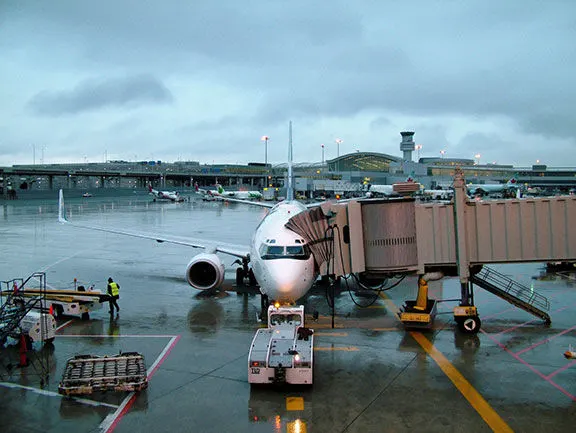
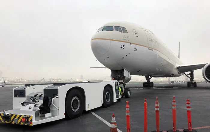
Taxiing is the controlled movement of the airplane under its own power while on the surface. Since an airplane is moved under its own power between a parking area and the runway, the pilot must thoroughly understand and be proficient in taxi procedures.
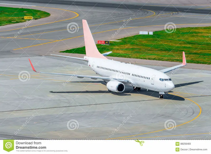
Taxiing (rarely spelled taxying) is the movement of an aircraft on the ground, under its own power, in contrast to towing or pushback where the aircraft is moved by a tug. ... An airplane uses taxiways to taxi from one place on an airport to another; for example, when moving from a hangar to the runway.
PART 5: Learn about take off power, tyre design, rolling resistance, tyre pressure, brake forces when landing.
SOLUTION:
Takeoff is the phase of flight in which an aerospace vehicle leaves the ground and becomes airborne.
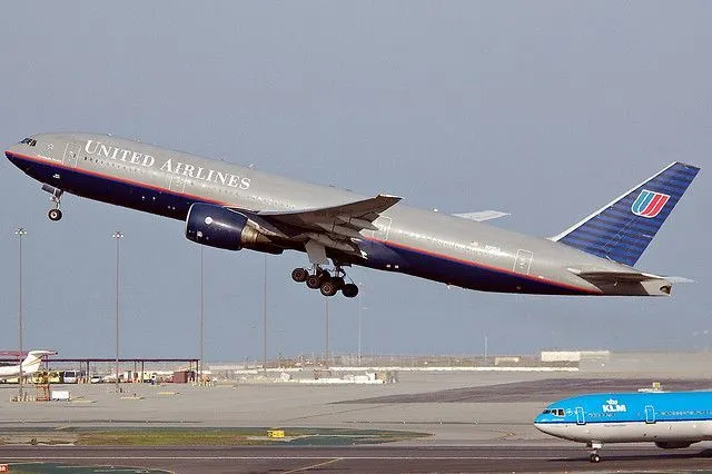
For aircraft that take off horizontally, this usually involves starting with a transition from moving along the ground on a runway For ballons, helicopters and some specialized fixed-wing aircraft (VTOL aircraft such as the Harrier), no runway is needed.
Contents
1)Horizontal Take Off
1.1)Power settings
1.2)Speed required
1.3)Assisted take off
2)Vertical takeoff
2.1)VTOL
2.2)Rocket Launch
Horizontal takeoff :
Power setting :
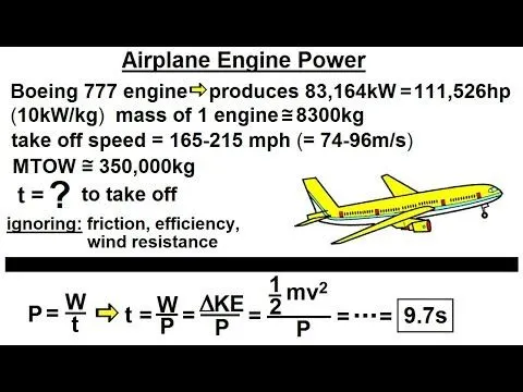
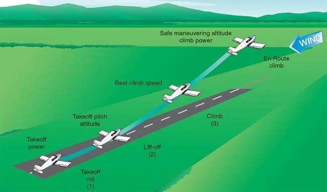
For light aircraft, usually full power is used during takeoff. Large transport category (airliner) aircraft may use a reduced power for takeoff, where less than full power is applied in order to prolong engine life, reduce maintenance costs and reduce noise emissions. In some emergency cases, the power used can then be increased to increase the aircraft's performance. Before takeoff, the engines, particularly piston engines are routinely run up at high power to check for engine-related problems. The aircraft is permitted to accelerate to rotation speed (often referred to as Vr). The term rotation is used because the aircraft pivots around the axis of its main landing gear while still on the ground, usually because of gentle manipulation of the flight controls to make or facilitate this change in aircraft attitude (once proper air displacement occurs under / over the wings, an aircraft will lift off on its own; controls are to ease that in).
The nose is raised to a nominal 5°–15° nose up pitch attitude to increase lift from the wings and effect liftoff. For most aircraft, attempting a takeoff without a pitch-up would require cruise speeds while still on the runway.
Three airliners taking off simultaneously (note similar pitch attitudes)
Fixed-wing aircraft designed for high-speed operation (such as commercial jet aircraft) have difficulty generating enough lift at the low speeds encountered during takeoff. These are therefore fitted with high lift devices, often including slats and usually flaps which increase the camber and often area of the wing, making it more effective at low speed, thus creating more lift. These are deployed from the wing before takeoff, and retracted during the climb. They can also be deployed at other times, such as before landing.
The speeds needed for takeoff are relative to the motion of the air (indicated air speed). A head wind will reduce the ground speed needed for takeoff, as there is a greater flow of air over the wings. Typical takeoff air speeds for jetliners are in the range of 240–285 Km/h (130–154 Kn; 149–177 mph). Light aircraft, such as a Cessna 150, take off at around 100 Km/h (54 Kn; 62 mph). Ultralights have even lower takeoff speeds. For a given aircraft, the takeoff speed is usually dependent on the aircraft weight; the heavier the weight, the greater the speed needed.Some aircraft are specifically designed for short takeoff and landing(STOL, which they achieve by becoming airborne at very low speeds.
Speed required
The takeoff speed required varies with aircraft weight and aircraft configuration (flap or slat position, as applicable), and is provided to the flight crew as indicated airspeed
Operations with transport category aircraft employ the concept of the takeoff V- speeds V1, VR and V2. These speeds are determined not only by the above factors affecting takeoff performance, but also by the length and slope of the runway and any peculiar conditions, such as obstacles off the end of the runway. Below V1, in case of critical failures, the takeoff should be aborted; above V1 the pilot continues the takeoff and returns for landing. After the co-pilot calls V1, they will call VR or "rotate," marking speed at which to rotate the aircraft. The VR for transport category aircraft is calculated such as to allow the aircraft to reach the regulatory screen height at V2 with one engine failed. Then, V2 (the safe takeoff speed) is called. This speed must be maintained after an engine failure to meet performance targets for rate of climb and angle of climb.
In a single-engine or light twin-engine aircraft, the pilot calculates the length of runway required to take off and clear any obstacles, to ensure sufficient runway to use for takeoff. A safety margin can be added to provide the option to stop on the runway in case of a rejected takeoff In most such aircraft, any engine failure results in a rejected takeoff as a matter of course, since even overrunning the end of the runway is preferable to lifting off with insufficient power to maintain flight.
If an obstacle needs to be cleared, the pilot climbs at the speed for maximum climb angle (Vx), which results in the greatest altitude gain per unit of horizontal distance travelled. If no obstacle needs to be cleared, or after an obstacle is cleared, the pilot can accelerate to the best rate of climb speed (Vy), where the aircraft will gain the most altitude in the least amount of time. Generally speaking, Vx is a lower speed than Vy, and requires a higher pitch attitude to achieve.
Assisted takeoff
Tow line and towing aircraft seen from the cockpit of a glider
Assisted takeoff is any system for helping aircraft into the air (as opposed to strictly under its own power). The reason it might be needed is due to the aircraft's weight exceeding the normal maximum takeoff weight insufficient power, or the available runway length may be insufficient, or a hot and high airfield, or a combination of all four factors. Assisted takeoff is also required for gliders which do not have an engine and so are unable to take off by themselves.
Vertical takeoff
Vertical takeoff refers to aircraft or rockets that take off in a vertical trajectory. Vertical takeoff eliminates the need for airfields. Most vertical take off aircraft are also able to land horizontally, but there were certain rocket powered aircraft of the Luftwaffe that only took off vertically, landing in other ways.
Vertical take-off and landing (VTOL) aircraft include fixed wing aircraft that can hover, takeoff and land vertically as well as helicopters and other aircraft with powered rotors, such as tiltrotors. Some VTOL aircraft can operate in other modes as well, such as CTOL (conventional take-off and landing), STOL (short take-off and landing), and/or STOVL (short take-off and vertical landing). Others, such as some helicopters, can only operate by VTOL, due to the aircraft lacking landing gear that can handle horizontal motion. VTOL is a subset of V/STOL (vertical and/or short take-off and landing).
Rocket launch
The takeoff phase of the flight of a rocket is called "rocket launch". Launches for orbital space flights, or launches into interplanetary space, are usually from a fixed location on the ground, but may also be from a floating platform such as the San Marco Platform, or the Sea Launch vessel.

ROLLING RESISTANCE:
Rolling resistance force (Frr)
Frr = µrr * mg
Here µrr is the rolling resistance coefficient, m is mass of the vehicle & g is gravitational force. µrr depends on the road material, vehicle tyre material, vehicle tyre pattern, liquids on the road, tyre pressure & tyre temperature etc.,
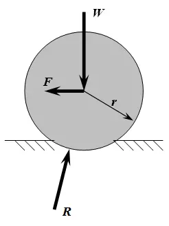
Rolling resistance, sometimes called rolling friction or rolling drag, is the force resisting the motion when a body (such as a ball, tire, or wheel) rolls on a surface. It is mainly caused by non-elastic effects; that is, not all the energy needed for deformation (or movement) of the wheel, roadbed, etc., is recovered when the pressure is removed. Two forms of this are hysteresis losses (see below), and permanent (plastic) deformation of the object or the surface (e.g. soil). Another cause of rolling resistance lies in the slippage between the wheel and the surface, which dissipates energy. Note that only the last of these effects involves friction, therefore the name "rolling friction" is to an extent a misnomer.
In analogy with sliding friction, rolling resistance is often expressed as a coefficient times the normal force. This coefficient of rolling resistance is generally much smaller than the coefficient of sliding friction.[1]
Any coasting wheeled vehicle will gradually slow down due to rolling resistance including that of the bearings, but a train car with steel wheels running on steel rails will roll farther than a bus of the same mass with rubber tires running on tarmac. Factors that contribute to rolling resistance are the (amount of) deformation of the wheels, the deformation of the roadbed surface, and movement below the surface. Additional contributing factors include wheel diameter,[2] load on wheel, surface adhesion, sliding, and relative micro-sliding between the surfaces of contact. The losses due to hysteresis also depend strongly on the material properties of the wheel or tire and the surface. For example, a rubber tire will have higher rolling resistance on a paved road than a steel railroad wheel on a steel rail. Also, sand on the ground will give more rolling resistance than concrete. Sole rolling resistance factor is not dependent on speed.
TYRE DESIGN:
Aircraft Tyre | Design and Construction
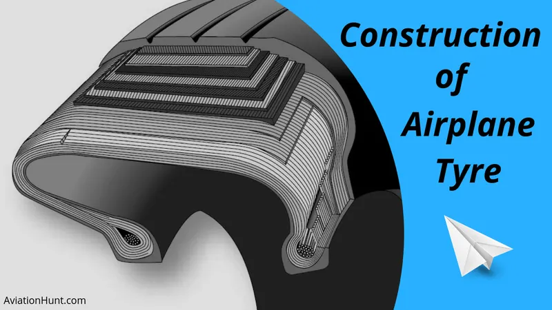
Many aviation technicians are not aware of the critical design factors of aircraft tyre in use today. I will discuss step by step, but first, I would like to ask the importance of tyre in aircraft.
Why are tyres important in Aircraft?
When it comes to safety, tyres are one of the most important components of aircraft. They help to absorb the shock of landing and provide cushioning. It also provides the necessary traction for braking and stopping of an aircraft.
An aircraft tyre is designed to withstand extremely heavy loads while landing, take off, taxing, and parking. The number of wheels required for aircraft increases with the weight of the aircraft, as the weight of the aeroplane needs to be distributed more evenly.
A Boeing 737NG & 737MAX uses 6 wheels, Boeing 787 uses 10 wheels, Boeing 777 uses 14 wheels and Airbus A380 uses 22 wheels. Aircraft tyres work under extreme conditions, carrying up to 340 tons and accelerating at over 250 km/hour at takeoff, in addition to enduring varied environmental stress when in flight and taxiing.
Design and Construction of Aircraft tyre
Carcass plies are used to form the tire. They are sometimes called casing plies. An aircraft tyre is constructed for the purpose it serves.
They support the weight of an aircraft while it is on the ground.
It also provides the necessary traction for braking and stopping of an aeroplane.
Tyre also helps to absorb the shock of landing and provide cushioning the roughness of takeoff, roll-out, and taxi operations.
Unlike an automobile or truck tyre, it does not have to carry a load for a long period of continuous operation. However, an aircraft tyre absorbs the high impact loads of landing, and also it’s operating at high speeds for a short time when required.
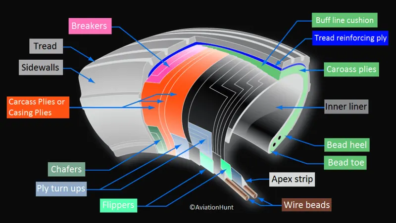
Let’s go through some technical aspects of the tyre.
Retreading – Retreading is methods of restoring a worn tyre by renewing the tread area or by renewing the tread area plus one or both sidewalls. Repairs are included in the tyre retreading process.
Load Rating – Load rating is the maximum permissible load at a specified inflation pressure.
Ply Rating – Ply Rating is used to identify the maximum recommended load rating and inflation pressure for a specified tyre. It is an index of tyre strength.
Speed Rating – The speed rating is the maximum takeoff speed to which the tyre has been tested.
Skid Depth – Skid depth is the distance between the tread surface and the deepest groove as measured in the mould.
Aircraft tyres must have an approved speed and load rating and have sufficient clearance when retracted through landing gear to allow for tyre growth. Tyre growth is the increase in the size of the tyre due to centrifugal forces at high speed.
Aircraft tyres may be Tube-type or Tubeless
Tubeless tyres are more advantageous over tube-type. There is no longer the use of tube-type tyre in recent aviation. Nowadays all airliners are using tubeless tyres. Tubeless that are meant to be used without a tube has the word TUBELESS on the sidewall of the tyre.
Aircraft tyres may be Radial or Bias
Almost all airliners are using Radial tyre. Bias is an older design, and it’s mainly used for road vehicles. Radial tyres have the word RADIAL on the sidewall. Radial tires are more expensive than bias-ply tyres. Radial tires are in demand because of their lower life cycle cost and long term value.
Are aviation tyres are conductive?
Yes, Today’s tyres are conductive. Aircraft tyres are manufactured with tread rubber with conducting compounds to permit earthing of static charges.
In early days when tyres were not sufficiently conductive, aircraft used to have a conductive strip hanging down from the axle of the landing gear. Upon landing, this strip would be the first part of the aircraft to touch the earth. This discharges any static electricity accumulated on the outer surfaces of the aircraft. Now you don’t see them anymore.
What is the purpose of Chines in aviation tyre
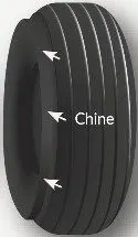
Chines are also called deflectors. Chine tyre used on the nose wheel of aircraft, specially fuselage-mounted jet engines. It diverts runway water away from the engine inlets.
Chines are circumferential protrusions that are moulded into the sidewall of nose tyres that deflect water sideways to help reduce excess water ingestion into the engines. Tyres may have chines on one or both sides, depending on the number of nose tyres on the aircraft.
Aircraft Tyre Standards
Each tyre manufacturer produces their own designs of the tyre with different tread patterns, wear patterns, wear limits etc, and in some cases, different names for the same part of the tyre. But all tyres must meet the approved standards before being accepted by the FAA or CAA.
All commercial aircraft tyres approved under FAA Requirement Technical Standard Order (TSO) C62. A TSO is a minimum performance standard for specified materials, parts, and appliances used on civil aircraft.
TYRE PRESSURE:
Inflation Tyre Pressure Checking
It is essential that aircraft tyres be maintained at the correct inflation pressure. Any deviation from specified operational inflation pressures will affect both the performance and safe operation of the tyre.
Under-inflation will increase tyre deflection resulting in excessive heat generation and over-stressing of the carcass leading to either ply or tread separation.
Over-inflation will accelerate wear in the tread crown area and render the tyre more susceptible to foreign object damage (FOD). Therefore it is essential that tyre inflation pressures are checked and adjusted on a regular basis, at least every 24 hours or preferably at each pre-flight inspection.
Tyres on multi-bogie gears can not be visually inspected for equal deflection, because if one tyre is under-inflated then the companion will take the load of both tyres and will, therefore, appear at equal deflection, in any case, visual inspection is totally unsatisfactory and dangerous.
All inflation pressures in rating tables are usually for unloaded tyres ambient temperature (cold). A two hour cooling time should be allowed after landing before checking inflation pressure.
Tyre Pressure – Loaded vs Unloaded Condition
Most tyres are put into service at loads less than the rated load. In order to maintain the design operating conditions of the tyre, the operating inflation pressure is adjusted accordingly. This adjustment is in direct proportion to the rated load of pressure.
Many inflation checks are made while the tyre is mounted on the aircraft. Under loaded conditions, the measured pressure of the tyre will be a value 4% greater than the unloaded pressure due to the weight of an aircraft.
Tyre Pressure vs Temperature Relationship
The relationship between tyre temperature and tyre pressure is proportional. As the temperature of the tyre increases, so the pressure will also increase. The inverse is also true. When the tyre temperature is reduced, the pressure will also reduce.The manufacturer has found that as a general rule, a temperature change of 3°C will result in a tyre pressure change of approximately 1%.
BRAKE FORCES:
The 787 braking system
Stopping a 200-tonne aircraft landing at 180 mph requires a lot of braking force. To do this, the 787 has one brake unit on each of the eight wheels on the main gear assembly. On other aircraft types, the brake units are powered by the hydraulics system. An electrical signal is sent from the flight deck to hydraulic actuators near the main landing gear. Here, hydraulic fluid at 3,000 pound per square inch is used to force the brake unit against the wheel, thus slowing it down.
This system works fine, but the pipes and actuators that form this part of the hydraulic system come at a considerable weight cost. Extra weight means more fuel burn, which in turn increases costs and carbon emissions. What if the brakes could be powered a different way?
The brakes on the 787 Dreamliner work differently to those on other types.
Thats the case on the 787 Dreamliner Designers did away with the use of the hydraulic system and all its associated architecture and instead used electricity to power the brakes. When the pilots press on the brake pedals, an electrical signal is sent to the brake unit on the wheel. Here, electrically powered actuators are used to press the carbon brake disc against the wheel, slowing it down.
By changing to electric brakes, a 787-8 saves 141 pounds per aircraft and a 787-9 saves 245 pounds. The brakes are also known as “plug and play” because electrical wiring replaces the traditional hydraulics and it’s much easier and quicker to change the brake units when needed. Smart features also allow engineers to monitor the brake performance more closely, giving a real-time measurement of wear on the carbon disks.
Electric brakes
The brake system on the 787 Dreamliner is controlled by the pilots pressing the tops of the rudder pedals under their feet, demanding the rate of braking which they require. This sends an electronic signal to the Left and Right Brake System Control Units (BSCUs).
These then send signals to the four Electronic Brake Actuator Controllers (EBAC) which control the rate of braking on the wheels. Each wheel has four Electric Brake Actuators (EBA), a kind of piston which presses against the carbon brake discs.
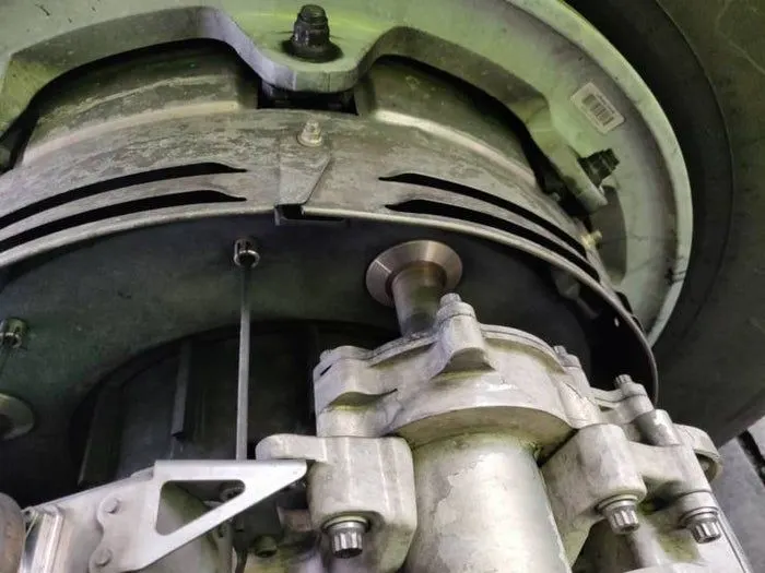
An Electric Brake Actuator (EBA) pressing against the brake disc. (Photo by Charlie Page/The Points Guy).
The brake disks themselves are made up of two parts. Firstly, there are the rotors. These are connected to the wheel by drive tabs (in the video below they are the black rectangles on the rotor disks). As these drive tabs are in contact with the inside of the wheel, they spin at the same speed. Depending on the brake manufacturer, there are either four or five of these rotors on each brake assembly.
The second part of the disks are the stators. These sit around each rotor and are fixed in place and thus don’t move. As the wheel turns, the rotors spin round inside the stators.
When the brakes are applied, the four EBAs apply pressure to the first stator. This in turn squeezes the stationary stators up against the spinning rotors and it’s this friction which slows the wheel down.
Anti-skid protection
When landing on slippery runways, there’s a chance that the wheels may start to skid as the brakes are applied. To stop this from happening and to maintain maximum effective braking, each wheel has anti-skid protection.
Using a variety of sources to determine the aircraft speed, the brake units know how fast the wheels should be spinning. If that speed drops significantly, it’s because the current brake pressure on that wheel is too great and the wheel is just skidding over the surface.
In this situation, the anti-skid system automatically reduces the braking on that wheel to a point where the skid stops before reapplying the pressure. All this is done in a fraction of a second.
Autobrake
Pressing on the brakes is pretty straight forward when taxiing in a straight line at low speed. However, when we’re landing in strong winds, it can be a little tricky. We need to use our feet on the rudder pedals to line the nose of the aircraft up with the runway centerline at the last moment. Then, whilst holding that position, slide our feet up to press the toe brakes. Really not very easy when moving at 160 mph.
To help us get the braking underway as soon as we touch down, we have the autobrake system.This provides automatic braking at a preselected rate as soon as the aircraft senses that it is on the ground. It also provides full braking pressure in the case of a rejected takeoff if the speed is above 85 knots (98 mph).
Brake temperature indication
With friction comes heat. As a result, each brake unit displays its temperature on the wheel synoptic page in the flight deck. Here, numerical values relating to brake temperature are shown next to each wheel. A value of 0-4.9 is in the normal range. When a temperature becomes 5.0 or above, an advisory message is displayed to the pilots.
Should the brakes become too hot, there’s a chance that the heat transferred to the wheels could cause the tires to explode. To stop this from happening, when a certain temperature is reached, fuse plugs in the tires melt. This allows the air to be released safely and slowly deflate the tires.
Parking brake
Every so often we need to engage the brakes and keep them on. This is particularly useful on long taxis to the runway and obviously when parked at the gate. The park brake is set by fully pressing down both toe brakes and pulling the parking brake lever up. With this set, we can then release the pressure from the pedals. To release, we just press the brake pedals again.
A helping hand
In addition to the brakes, there are two other systems which help slow the aircraft down on landing. The spoilers and the reverse thrust.
Spoilers
Have you noticed the large panels on the top of the wings raise up on touch down? These are the called the spoilers as they literally spoil the airflow over the wing. This dumps any remaining lift the wings are generating, allowing the wheels to take all the weight and achieve maximum efficiency from the brakes.
Reverse thrust
The final part of the braking process comes from reverse thrust. Just after we have touched down, we pull two levers on top of the thrust levers to engage the reverse thrust, a sort of “reverse gear” for jet engines.
This causes blockers inside the engine to deploy and a door in the side of the engine to slide backward. The air which normally leaves the engine out the back is deflected forward by the blockers and out through the door.
There are two stages of reverse thrust — idle reverse and max reverse. Idle reverse is used on most landings and max reverse is used when the landing performance requires it, normally when the aircraft is landing at hot or high elevation airfields.
This forward directed airflow helps slow the aircraft down but is most efficient at high speeds. If using max reverse, we drop this down to idle reverse at 60 knots (70 mph) and then back to normal thrust as we vacate the runway at around 20 knots (25 mph).
PART 6: With necessary assumptions, calculate the force and power required to push / pull an aircraft by a towing vehicle.
SOLUTION:
The various forces acting on the aircraft while pushing and pulling are
1)Rolling resistance force (Frr)
2)Aerodynamic drag force (Fad)
3)Linear acceleration force (Fla)
Methods or Formulas used to obtain the solution :
Vehicle propulsion power or tractive effort power is denoted by (Pte) required to overcome the possible opposing forces when the vehicle is going with a constant speed. So, the possible opposing forces are listed below:
1)Rolling resistance force (Frr)
Frr = µrr * mg
Here µrr is the rolling resistance coefficient, m is mass of the vehicle & g is gravitational force. µrr depends on the road material, vehicle tyre material, vehicle tyre pattern, liquids on the road, tyre pressure & tyre temperature etc.,
2)Aerodynamic drag force (Fad)
Fad = ½ * ρ * A * Cd * v^2
Here ρ air density kg/m^3
A is frontal area of the vehicle m^2
Cd is air drag coefficient
V is velocity m/s
Generally aerodynamic drag force depends on two components like shape of the drag, skin friction of vehicle.
3)Linear acceleration force (Fla)
Generally acceleration power or the forces required by the vehicle is only for a short duration here in this case we assume the vehicle is going with a constant speed. Therefore no acceleration forces are considered
Total tractive effort force is calculated as
Fte = Frr + Fad +
= µrr * mg + ½ * ρ * A * Cd * v^2
Total tractive effort force or vehicle propulsion power (P) is calculated as
P (kw) = Fte * v
Solution: Assuming vehicle is running with constant speed and there is no hill climbing situation considering here
Step1: calculating Rolling resistance force (Frr):
a)Rolling resistance coefficient (µrr) =0.025
b)Considering the Total mass of the aircraft for the below model including kerb weight + pay load (m) is
|
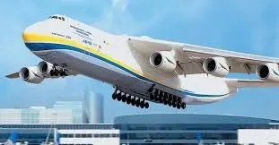
Antonov An 225 |
640,000 kg |
c)Gravity (g) =9.806 m/s^2 is the standard gravity value of earth surface
From the formula of rolling resistance force [Frr = µrr * m*g]
Frr = a * b * c
=0.025*640000*9.806
=156896 newtons
By using the same formula and by varying the µrr, m, g parameters we can obtain different force values.
Step2: calculating Aerodynamic drag force (Fad):
d)Air density (ρ) =1.25 kg/m^3
e)Width = 80 metres
f)Height = 25 meters
g)Speed / velocity = 20 kmph = 5.5 m/s
h) Frontal area of the vehicle = width * height = 2000
i)Drag coefficient (Cd) = 0.43
For calculating Aerodynamic drag force (Fad) the formula used is
Fad = ½ * ρ * A * Cd * v^2
=0.5 * 1.25 * 2000 * 0.43 * (5.5)^2
= 16259.37 newtons
By using the same formula and by varying the ρ,A,Cd,v parameters we can obtain different force values.
Step3:
Total tractive effort force is calculated as
Fte = Frr + Fad
= µrr * mg + ½ * ρ * A * Cd * v^2
=156896 + 16259.37
=173155.375
Total tractive effort force or vehicle propulsion power (P) required to push / pull an aircraft by a towing vehicle
is calculated as
P (kw) = Fte * v
=(173155.375 *5.5) / 1000
= 952.35 kw
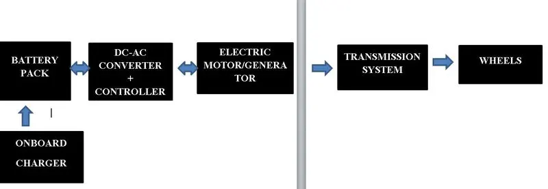
PART 7: Design an electric powertrain with type of motor, it’s power rating, and energy requirement to fulfill aircraft towing application. Estimate the duty cycle range to control the aircraft speed from zero to highest. Make all required assumptions. Prepare a table of assumed parameters. Draw a block diagram of powertrain.
SOLUTION:
The Assumptions are
Mass of aircraft = 640,000 kg
Rolling resistance coefficient (µrr) =0.025
Frontal area of the vehicle = width * height = 2000
Drag coefficient (Cd) = 0.43
Speed / velocity = 20 kmph = 5.5 m/s
Air density (ρ) =1.25 kg/m^3
Gravity (g) =9.806 m/s^2
Mass of towing vehicle = 100000 kg
Towing vehicle Drag coefficient (Cd) = 0.35
Radius of the towing vehicle = 0.5m
Time = 3 minutes
From the assumptions Aerodynamic drag force (Fad) is calculated as
Fad = ½ * ρ * A * Cd * v^2
=0.5 * 1.25 * 2000 * 0.43 * (5.5)^2
= 16259.37 newtons
Rolling resistance force calculated as [Frr = µrr * m*g]
Frr = a * b * c
=0.025*640000*9.806
=156896 newtons
Total tractive effort force is calculated as
Fte = Frr + Fad
= µrr * mg + ½ * ρ * A * Cd * v^2
=156896 + 16259.37
=173155.375
Total tractive effort force or vehicle propulsion power (P) required to push / pull an aircraft by a towing vehicle
is calculated as
P (kw) = Fte * v
=(173155.375 *5.5) / 1000
= 952.35 kw
Torque calculated = Force * Radius
=173155.3 * 0.5
=86577.65 N-m
Energy calculated = Power * Time
= 952.35 * (180/ 3600)
= 47.61 kwh
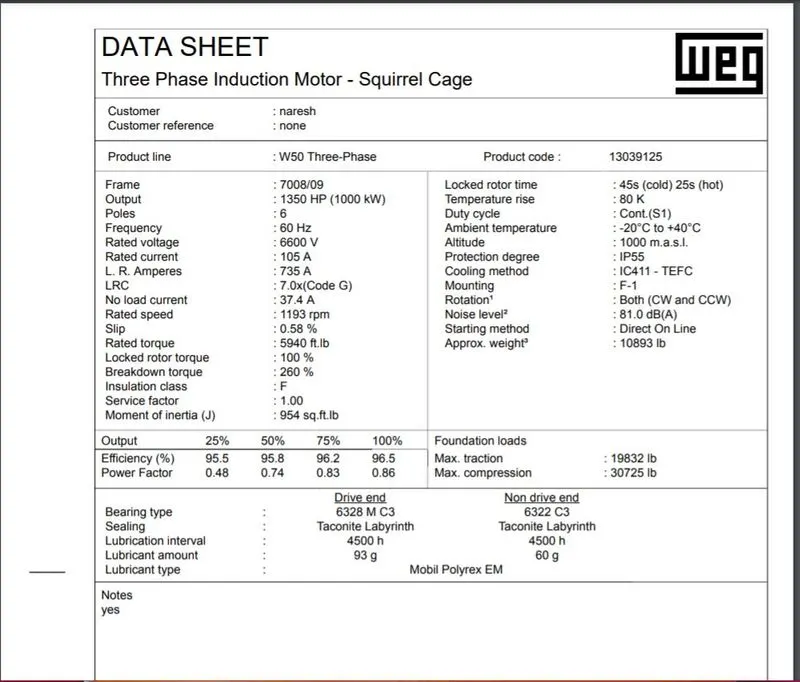
The above Induction Motor Squirrel cage type is chossed with an input power of 1000 kw to satisfy the load of 952 kw
Therefore the duty cycle calculated is:
Duty cycle = output power / input power
= 952.35/1000
= 0.95
The duty cycle range to control the aircraft speed from zero to highest speed of 5.5m/s in 3 minutes is 0.95.
BLOCK DIAGRAM OF THE POWER TRAIN :