Project 1 Mechanical design of battery pack
Aim: Prepare a detailed battery pack drawing along with its enclosure.
Objective:
- Create a battery pack of 18 KWh capacity by using ANR26650M1-B cells.
- Understand the mechanical step of building a battery pack.
Theory:
Battery Pack:
A battery pack is a set of any number of (preferably) identical individual cells. They may be configured in a series, parallel or a mixture of both to deliver the desired voltage, capacity, or power density. The term battery pack is often used in reference to cordless tools, radio-controlled hobby toys, and battery electric vehicles.
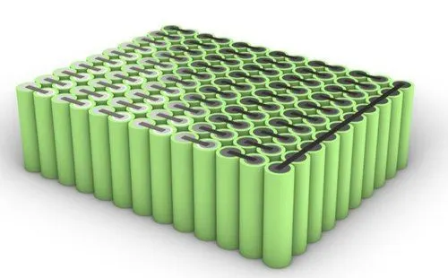
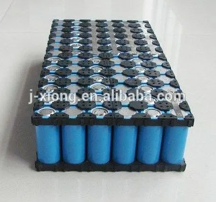
Components of battery packs include the individual cells, and the interconnects which provide electrical conductivity between them. Rechargeable battery packs often contain a temperature sensor, which the battery charger uses to detect the end of charging. Interconnects are also found in batteries as they are the part which connects each cell, as per our requirement battery connection configuration made. If we want more voltage than the individual one cell then series connection is made and if we want more current capacity then connect cells in parallel mannar. And it looks similar to the figure below.
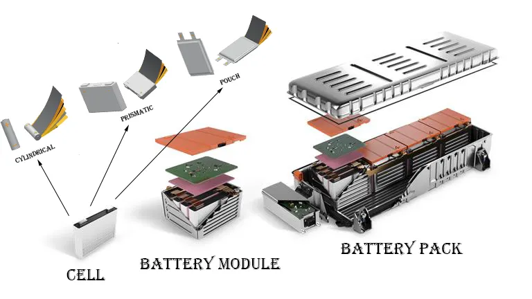
But in electric vehicles or any bigger battery pack is not made directly from cells. First made module by making series or parallel connection in between cell and its called series or parallel module. And then this module again connected series or parallel as per our requirement and designed the battery pack. Due to these methods it provides flexibility in electrical connection, mechanical placement and thermal arrangement.
Battery Pack Major Component:
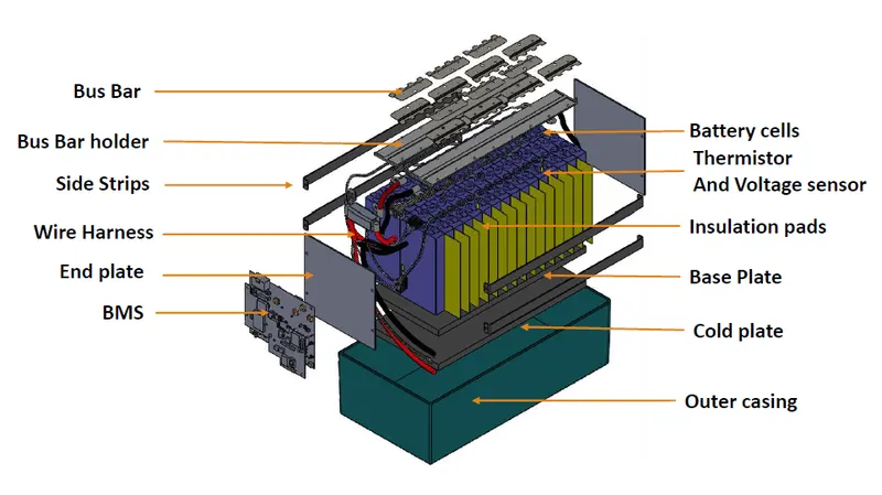
Battery Cells: Cells are the most important component in the battery pack. In these cells we can store the electrical energy into the chemical form.
Thermistor and Voltage Sensor: It is used for calculating the temperature and voltage of the battery pack for safety and measurement purposes.
Insulation Pads: It insulates the two adjustan battery cells.
Base Plate: It is used for holding the entire battery pack.
Cold Plate: It is a thermal management component for maintaining the battery pack temperature within the limits.
Busbar: It is used for making connections between two cells.
Busbar Holder: This holder holds the busbar at a proper position.
End Plates: End plates used for applying the required mechanical pressure on the battery pack in a distributed manner from the side.
Side Strips: These strips hold the end plates and assert pressure on end plates.
Wire Harness: This wire used for connecting the module also makes connection from battery pack to appliances.
Battery Management System (BMS): These systems manage the battery or cells in a proper manner.
Outer Casing: It provides a platform to the battery pack.
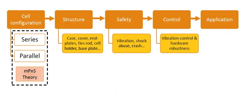
Battery Pack Mechanical Design Stages:
Battery Cells:
A cell is the smallest unit of a battery, comprising four key components including cathode, anode, electrolyte and separator. The characteristics of a battery cell play a pivotal role in the overall performance of electrified vehicles. There are various forms of a cell such as prismatic, cylindrical, and polymer for automotive applications. A module consists of multiple cells connected in series and/or parallel, encased in a mechanical structure.
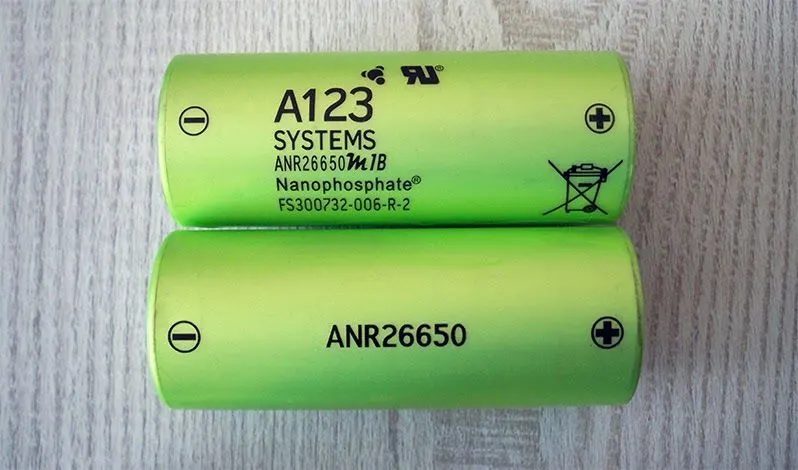
In our case we used A123 Systems company cell model ANR26650M1-B for making an 18 KWh capacity battery pack. A123’s high-performance Nanophosphate lithium iron phosphate (LiFePO4) battery technology delivers high power and energy density combined with excellent safety performance and extensive life cycling in a lighter weight, more compact package. These cells have low capacity loss and impedance growth over time as well as high usable energy over a wide state of charge (SOC) range, allowing our systems to meet end-of-life power and energy requirements with minimal pack oversizing.
Cell Technical Specification:
|
Cell Parameters |
Parameters Values |
|
Cell Dimension |
ø 26 x 65 mm |
|
Cell Weight |
76 gm |
|
Cell Capacity (nominal/minimum) (0.5C Rate |
2.5/2.4 Ah |
|
Nominal Voltage |
3.3 V |
|
Internal Impedance (1kHz AC typical) |
6 mΩ |
|
Power* |
2600 W/Kg |
|
Recommended Standard Charge Method |
2.5A to 3.6V CCCV, 60 min |
|
Recommended Fast Charge Method to 80% SOC |
2.5A to 3.6V CCCV, 60 min |
|
Maximum Continuous Discharge |
50 A |
|
Maximum Pulse Discharge (10 seconds) |
120 A |
|
Cycle Life at 20A Discharge, 100% DOD |
> 1000 Cycles |
|
Operating Temperature |
-30°C to 55°C |
|
Storage Temperature |
-40°C to 60°C |
* ~200W as measured by A123 modified HPPC Method @ 23°C, 50% SOC, 10 second discharge.
Cell Performance Plot:
Discharge Characteristic:
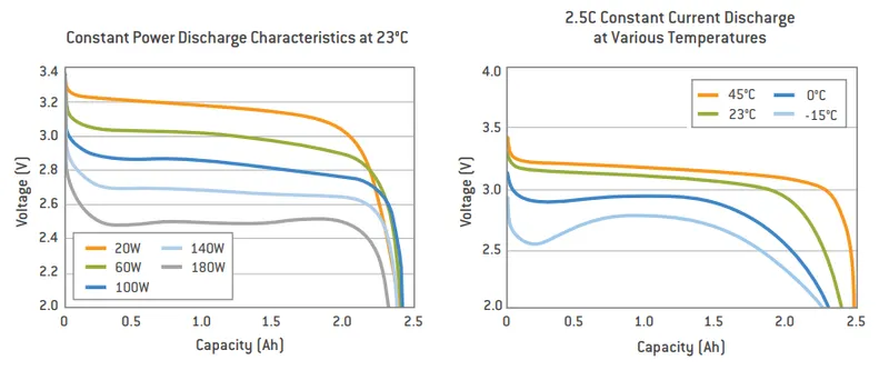
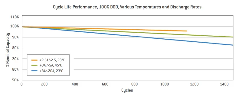
Cycle Life Performance:
Cells configuration:
We are building a battery of 18 KWh capacity for which I assume the battery pack nominal voltage is 400 V. Therefore, its current capacity will be 45 Ah (18000/400).
Series cells = battery pack nominal voltage ÷ Cell nominal voltage.
Series cell = 400 V ÷ 3.3 V = 122
Parallel Cell = battery current capacity ÷ cell current capacity
Parallel Cell = 45 Ah ÷ 2.5 Ah = 18
Total number of cells = series cells ⨯ parallel cells
Total number of cells = 122 ⨯ 18 = 2196
Therefore, the battery pack cell configuration is 18P122S.
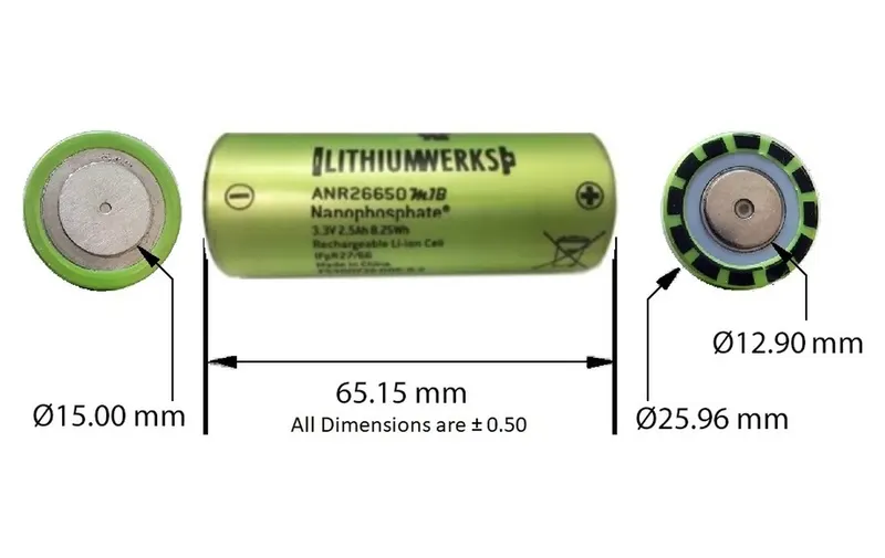
Cell Dimension:
Battery Pack Dimension:
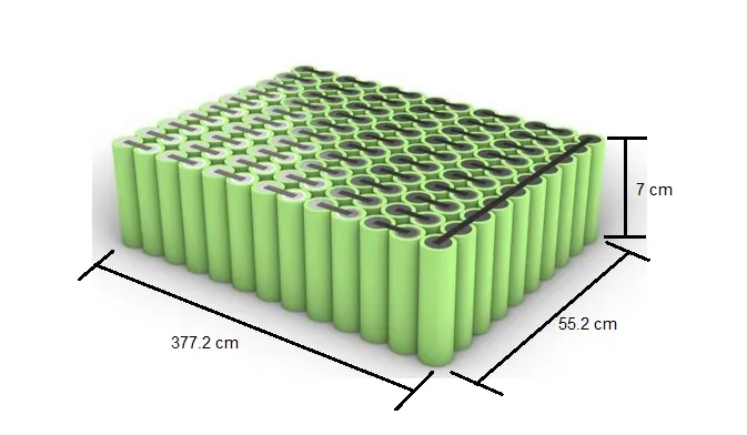
I assume, all cell 2196 are placed on the floor in one layer as shown in above figure and take 5 mm space in between two adjustan cells for thermal material or sensor. And for cell holding used cell holders on both sides of cells. Due to this holder cell height increases by 5 mm. Now we calculate the battery pack dimension:
Battery pack length = (Number of series connected cells ⨯ cell outer diameter) + ((Number of series connected cells - 1) ⨯ 5)
Battery pack length = (122 ⨯ 25.96) + (121 ⨯ 5) = 3772.12 mm = 377.2 cm
Battery pack width = (Number of parallel connected cells ⨯ cell outer diameter) + ((Number of parallel connected cells - 1) ⨯ 5)
Battery pack width = (18 ⨯ 25.96) + (17 ⨯ 5) = 552.28 mm = 55.2 cm
Battery pack height = Cell height + holder height
Battery pack height = 65.15 + 5 = 70.15 mm = 7 cm
Thus, battery pack dimension is 377.2 ⨯ 55.2 ⨯ 7 cm. So for our battery pack 145750 cm^3 volume space is required.
Spot Welding:
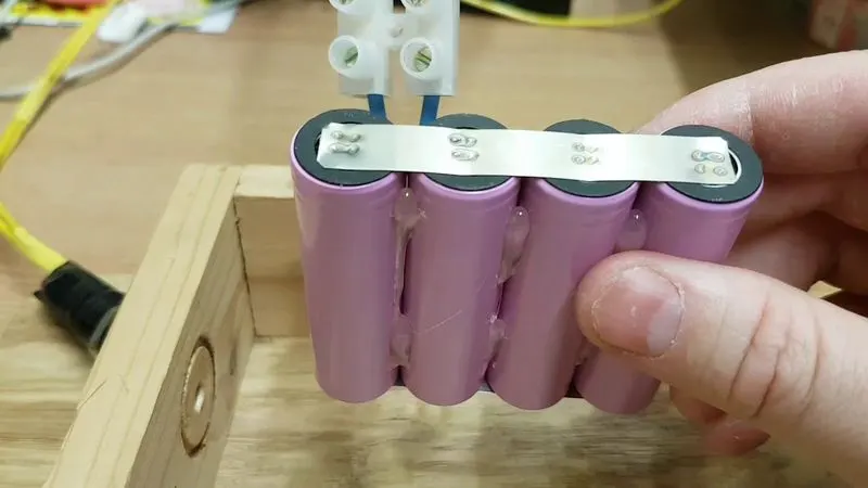
Battery packs are increasingly used to drive portable electric tools, such as electric bicycles, and electric hybrid vehicles. In these applications, the cells are connected in series or parallel to achieve the required voltage and capacity. There are three methods available for welding batteries: laser beam, ultrasonic and resistance spot welding but spot welding is most common in lithium ion cylindrical batteries.
The first takeaway of battery spot welding is that the process does not need any filler material. It involves pressure and heat applying to the welding area. A copper-alloy electrode transmits current through the material so that it melts and fuses the parts. The current is off while the pressure maintains to solidify the weld and so the joint forms. Usually, the current only runs in a flash whereas the pressure stays a bit longer.
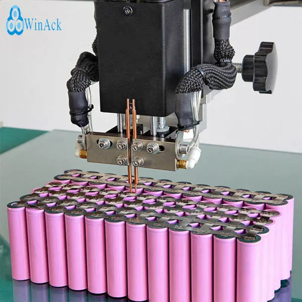
It can provide reliable results and form long-lasting welds. Because it uses the current flowing through the electrodes, there is no need for filler material. On this note, it is a cost-saving option. The other advantage is that the welding area is restricted. It only takes place exactly where the tip of the electrode makes contact. Therefore, the energy is focused and heat generation is reduced.
And on the other side there are some disadvantages , this method is not suitable for all materials, and the cost is relatively higher for mass-production lines when dealing with small-scale projects. Besides the cost issue, the welding quality is a concern if the process is not conducted properly. If the heat and pressure are not high enough, the joints will not be strong enough and hence susceptible to vibration or cracks. And it does not work well for irregular protrusions or hard-to-reach locations.
Mechanical Material:
Protection for battery packs from outer environment conditions like dust, vibration, shocks, etc. We can use the base plate, end plate, side strip, outer casing, etc. So now our 18 KWh battery pack is ready.
Mechanical Test Standards:
For validation of EV’s Battery pack, three different test standards are generally followed:
- Harmonic Vibration Test - AIS 048: 2009
- Shock Abuse Test - AIS 048: 2009
- Random Vibration test - SAE J 2380