Week - 4
Q. 1. Implement control logic of a “washing machine” using Stateflow as per given sequence
Ans:
Model:
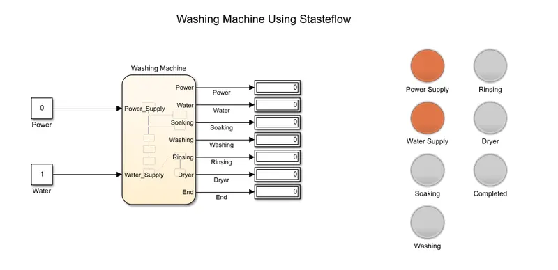
- In this model I used two constant blocks for power and water supply, a chart block for washing machine control logic,display and lamp for indicating which process is running.
- Below figure shows inside the chart block.
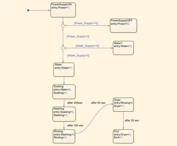
- Above control logic condition as per given condition, when run the simulation and power supply OFF then ‘PowerSupplyOFF’ state stops the process and indicates the red light on Power Supply lamp. Similarly if the water supply is OFF then also ‘Water1’ state stops the process and indicates through the lamp.
- If power and water supply is ON then remaining states are activated in sequence wise and completed the whole washing machine process as per mentioned in question.
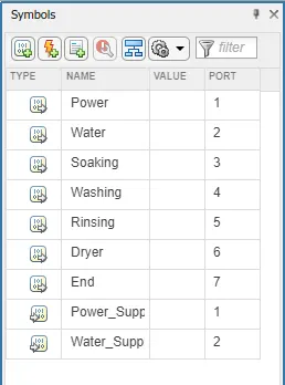
- Below figure shows the symbol pane i.e. define input and output data in the chart block.
Result:
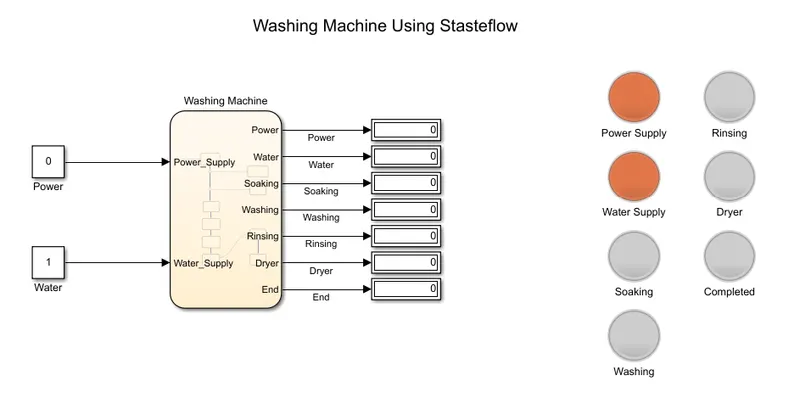
Case 1:
When power supply is OFF i.e. Power block value is less than equal to 0 then the process stops until the power supply is ON. The process has stopped, show the Power Supply lamp by flashing red light.
Case 2:
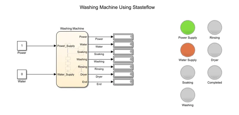
In this case power supply is ON but the water supply is OFF. Therefore the process has stopped and it shows the Water Supply lamp by flashing red light. But in this case the power supply is ON because of Power Supply glows green light.
Case 3:
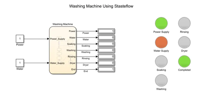
Now, in this case both power and water supply are ON therefore without any obstacle the washing machine process is started. After the whole process as per the design sequence Completed lamp glows. In this case also the Water Supply lamp glows red light because the after enough water cut the water supply.
Q. 2. Make a Simulink chart for the “Gear shift” logic as per below conditions:
Speed Range(kmph) Gear
0 to 15 1
16 to 25 2
26 to 40 3
41 to 60 4
Above 61 5
Give speed input while the simulation is running & display the gear number.
Ans:
Model:
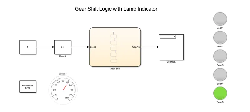
- For creating these gear shift logic model required a Stateflow chart block.
- Also providing desired speed input to the chart block I used slider gain and constant blocks. For showcasing the input speed I used Gauge.
- Similarly for easy identification of gear numbers I used Lamp.
- In the chart block I create a simple logic as per our given condition.Below figure shows the inside the chart block.
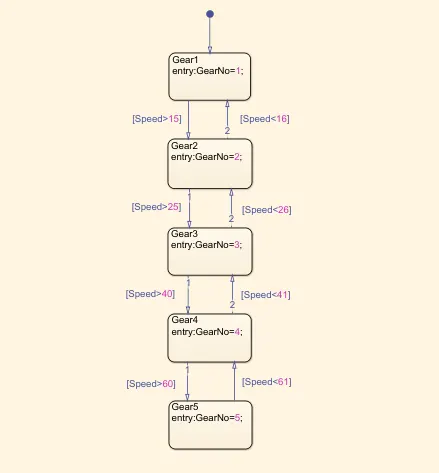
- According to these chart block logic when we vary the input speed, gear number also varies in display as per above transition assigned condition. Similarly respective gear lamps also glow.
- Also I used a Real time synchronization block for varying input speed at the time of simulation running.
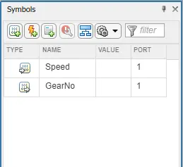
- In the above chart block I defined ‘Speed’ is an input data and ‘GearNo’ is an output data as shows in symbol pane of below figure.