Week-7 Challenge: DC Motor Control
Q. 1. A. Explain a MATLAB demo model named ‘Speed control of a DC motor using BJT H-bridge’.
Ans.
Model:
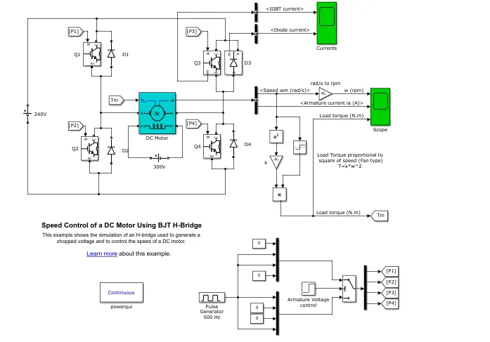
Figure 1: Speed Control of a DC Motor
- This model used four IGBT and four freewheeling diodes for controlling the speed of the DC motor. The DC motor gives 300 V dc voltage as a field winding voltage.
- Similarly 240 V dc voltage gives to armature winding and in between connects IGBT switches.
- Below figure shows the circuit diagram of BJT H-bridge speed controller of the DC motor.
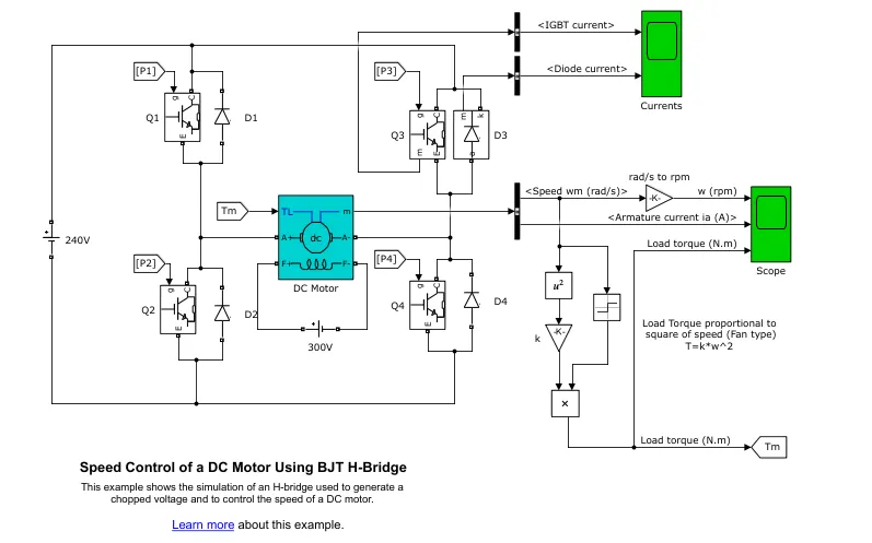
Figure 2: Circuit of BJT H-Bridge
- For this IGBT switch gives a pulse to the gate terminal for ON-OFF signal. This IGBT operates in such a way that when switch Q1 and switch Q4 are ON that time switch Q2 and switch Q3 are OFF.
- Below figures show the pulse generator circuit and pulses of the switches.
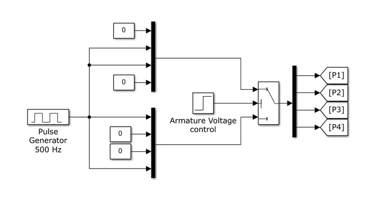
Figure 3: Pulse generator
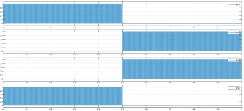
Figure 4: Switch Pulses
Results:
- In one scope show the IGBT and diode currents. When IGBT operates, the diode is closed and vice versa.
- Below figure shows the switch Q3 and diode D3 currents.
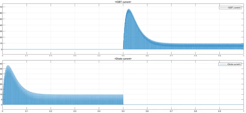
Figure 5: Switch Q3 Current
- In another scope show the motor parameters like armature current (A), rotor speed (rpm) and load torque (Nm).
- But actually in simulink DC Motor gives rotor speed in rad/sec then its converted in rpm by using gain block with 30/pi also load torque determined by using speed and square law.
- Below figure shows the rotor speed, armature current and load torque.
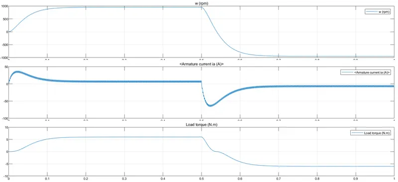
Figure 6
B. Comment on the armature current shoot-up from the scope results.
Ans.
- When switch Q1 and switch Q3 operate at that time voltage across is positive and rotor rotates like forward motoring mode.
- But when switch Q2 and switch Q3 are ON and switch Q1 and switch Q4 are OFF at that time voltage across is negative and the rotor rotates in the opposite direction like reverse motoring mode.
- These switch transition starting times require a high amount of negative torque, therefore the current shoots up to meet this torque requirement.
- Below figure shows the rotor speed, armature current and load torque.
- We can see that in the above figure when the switch transition happens at 0.5 sec the speed goes negative similarly torque goes negative. Therefore the armature current also shoots up negatively.
C. Refer to the help section of ‘The Four-Quadrant Chopper DC Drive (DC7) block’. Compare it with the H-bridge model.
Ans.
Model:
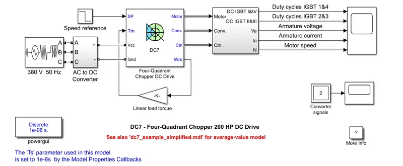
The 200 HP DC motor is separately excited with a constant 150 V DC field voltage source. The armature voltage is provided by an IGBT converter controlled by two PI regulators. The converter is fed by a 515 V DC bus obtained by rectification of a 380 V AC 50 Hz voltage source. In order to limit the DC bus voltage during dynamic braking mode, a braking chopper has been added between the diode rectifier and the DC7 block.
The first regulator is a speed regulator, followed by a current regulator. The speed regulator outputs the armature current reference (in p.u.) used by the current controller in order to obtain the electromagnetic torque needed to reach the desired speed. The speed reference change rate follows acceleration and deceleration ramps in order to avoid sudden reference changes that could cause armature overcurrent and destabilize the system. The current regulator controls the armature current by computing the appropriate duty ratios of the 5 kHz pulses of the four IGBT devices (Pulse Width Modulation). For proper system behaviour, the instantaneous pulse values of IGBT devices 1 and 4 are opposite to those of IGBT devices 2 and 3. This generates the average armature voltage needed to obtain the desired armature current. In order to limit the amplitude of the current oscillations, a smoothing inductance is placed in series with the armature circuit.
Results:
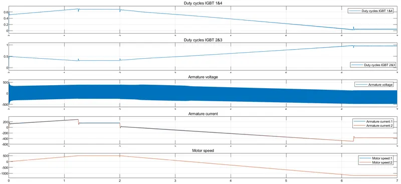
Comparison the H-bridge model with the Four-Quadrant Chopper DC Drive (DC7) block
- In the H-bridge model we operate only in two modes i.e. forward motoring mode and reverse motoring mode, but in DC7 we operate in all modes i.e. forward-reverse motoring mode and forward-reverse braking mode.
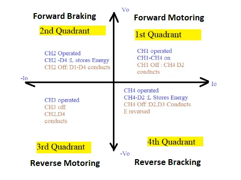
- In the H-bridge model only control the switch with pulses, but in the DC7 controlled for example for limiting DC bus voltage used braking chopper, a smoothing inductance is placed in series with the armature circuit for limiting the current oscillation, speed controller, current controller.
- Because of all these controllers, efficiency of the DC7 is higher than the H-bridge model.
Q. 2. Develop a 2-quadrant chopper using simulink & explain the working of the same with the relevant results.
Ans.
Two Quadrant Chopper:
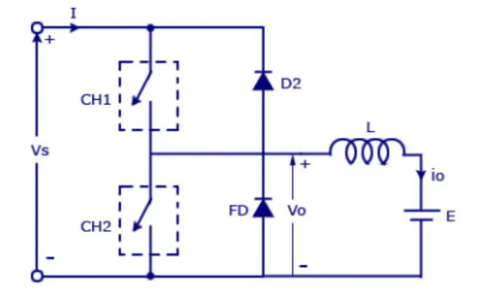
In this type of Chopper, the average voltage will be always positive but the average load current might be positive or negative. The two Switches CH1 and CH2 should not be turned on simultaneously as the combined action may cause a short circuit in supply lines. For regenerative braking and motoring these types of chopper configuration are used.
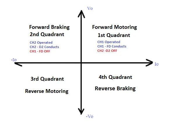
We will always get a positive output voltage V as the freewheeling diode FD is present across the load. When the chopper CH1 is on the current flows from source to load. The inductor stores energy. When Ch1 turns OFF the freewheeling diode starts conducting and the output voltage v will be equal to V . The direction of the load current i will be reversed. The current I will be flowing towards the source. The load current will be negative when the CH2 is on. The current completes its path through diode D2.
Simulink Model:
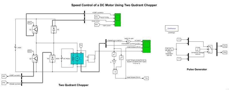
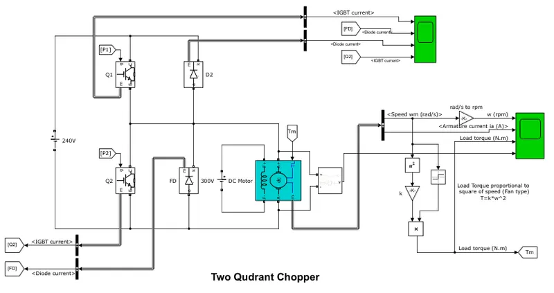
- In this model I used two IGBT (Q1, Q2) and two diodes (D2, FD) because it is a two quadrant chopper. DC motor connected series with IGBT Q1 and parallel with Q2 and diode D2, FD connected parallel with Q1 and Q2 respectively as per shown in above figure.
- Armature winding gives 240 V DC voltage and field winding gives 300 V DC voltage. Motor power is 5 HP and speed is 1750 RPM.
- Below figure shows the two quadrant chopper model.
- Similarly the figure below shows the pulse generation model for both IGBT switches.
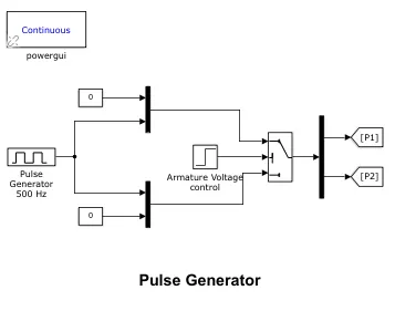
- The above figure shows the two results P1 and P2, this signal for switch Q1 and switch Q2 respectively. In that I used a pulse generator with 1 amplitude and 75% duty cycle, threshold switch and gave 0.5 amplitude step signal as a threshold signal to threshold switch and switch threshold value is 0.5.
- And my simulation time is 1 sec. So 1st half second lower pulse generator circuit operate i.e. P1 = 1 and P2 = 0 and the remaining half second upper pulse generator circuit operates i.e. now P1 = 0 and P2 = 1.
- Therefore starting 0.5 second Q1 and diode FD operate so remaining 0.5 second Q2 and D2 operate.
Result:
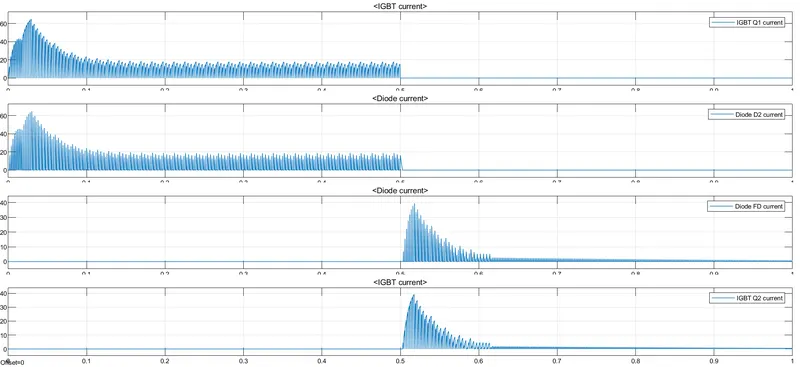
- We can see that in the figure below IGBT Q1 and diode FD similarly IGBT Q2 and diode D2 operate simultaneously. Both IGBT or diode do not operate simultaneously because they operate simultaneously then supply gets short circuited.
- Below figure shows the IGBT switches and diode current.
- Below figure shows the resultant angular speed of rotor (rpm), armature current (A), Load torque (Nm), Armature Voltage (V).
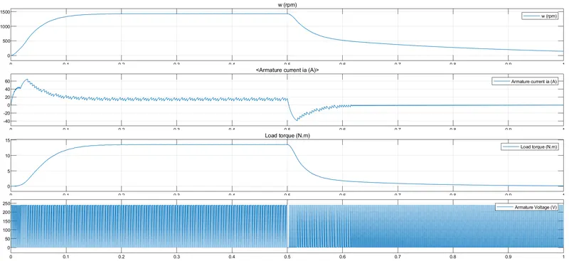
- In the above figure we can see that starting 0.5 second rotor speed, armature current and load torque are positive and after that remaining 0.5 second parameters goes negative, but armature voltage is always positive the whole time.
- That means the first 0.5 second motor operates as a forward motoring and the remaining 0.5 second it operates as a forward braking.
- Also I attached a simulation file ‘Two_Quadrant_Chopper.slx’ to the answer box.
Q. 3. Explain in a brief about operation of BLDC motor
Ans.
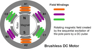
The BLDC (Brushless DC) motor rotor is made of permanent magnet, therefore there is no need to give supply to the rotor, so there is no any brush connected to the rotor that is why its name is a Brushless DC motor. This motor input supply is DC but it actually works on a three phase AC supply, it's a little bit similar to a three phase AC motor. Therefore BLDC motor mandatory required electronic commutator i.e. motor controller. Which is operated in such a way that the input supply is that manner that the motor rotor rotates according to our requirement with the help of attraction and repulsion principle. Motor input supply wave is trapezoidal, not a sine wave. In this motor hall sensor is placed inside the motor to sense the rotor speed.
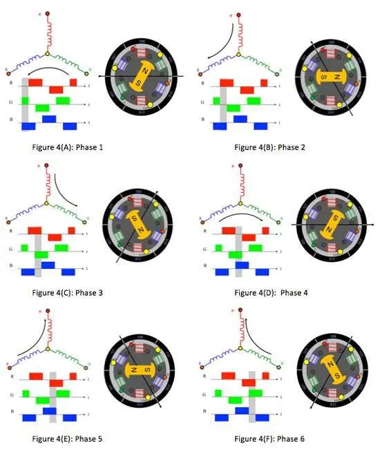
The BLDC motor's advantages is it produces less heat, operates at unity power factor, simple control, low maintenance and efficiency is high at peak load. In other hand the disadvantages is permanent magnet cost is high something like $50 per kilogram, because of permanent magnet we can not change the magnetic flux density therefore when increase the size of motor then magnetic losses also increase.
According to one of the tesla blog, the authors say that BLDC motors are used in the automotive industry at low load just like hybrid vehicle, plug-in hybrid vehicle, scooter, bicycle.