Project-1: Powertrain for aircraft in runways
Powertrain for aircraft in runways
Q. 1. Search and list out the total weight of various types of aircrafts.
Ans.
Types of Aircrafts: (Based on weight of aircraft)
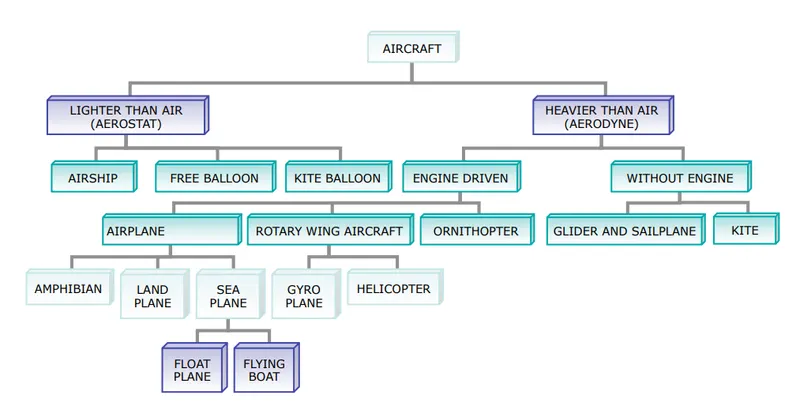
1. Lighter than air (Aerostat):
1.1. Airship:
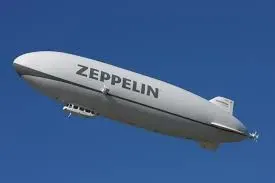
An airship or dirigible balloon is a type of aerostat or lighter-than-air aircraft that can navigate through the air under its own power. Aerostats gain their lift from a lifting gas that is less dense than the surrounding air. Once inflated with helium and after accounting for fuel, payload and ballast, it usually weighs in at 45-90 Kg.
1.2. Free Balloon:
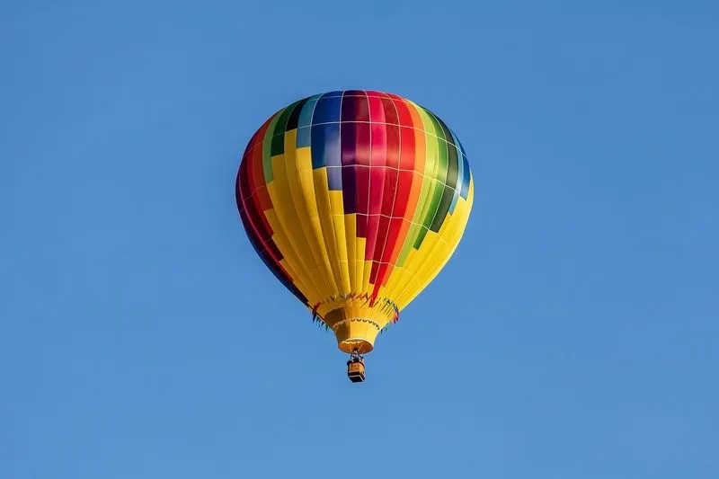
A balloon is a kind of aircraft that stays in the sky by floating. People fly in balloons mostly for fun.
A balloon is different from an airship. An airship is a floating aircraft that has an engine and can change its direction of movement. A balloon has no engine and has no way to change its direction of movement (except up and down). A balloon travels by moving with the wind. The bottom of the balloon is called the "basket" where people can sit or stand. The top of a balloon is a big cloth bag called the "envelope". In the air, the complete system, including the air inside the envelope, will weigh about 2500 Kg.
1.3. Kite Balloon:
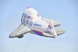
A kite balloon is a tethered balloon which is shaped to help make it stable in low and moderate winds and to increase its lift. It typically comprises a streamlined envelope with stabilising features and a harness or yoke connecting it to the main tether and a second harness connected to an observer's basket.
Kite balloons are able to fly in higher winds than ordinary round balloons which tend to bob and spin in windy conditions. They were extensively used for military observation during World War I and similar designs were used for anti-aircraft barriers, as barrage balloons in both world wars.
2. Heavier than air (Aerodyne):
2.1. Engine Driven:
2.1.1. Airplane:
2.1.1.1. Amphibian:
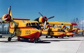
An amphibious aircraft or amphibian is an aircraft that can take off and land on both solid ground and water. Fixed-wing amphibious aircraft are seaplanes (flying boats and floatplanes) that are equipped with retractable wheels, at the expense of extra weight and complexity, plus diminished range and fuel economy compared to planes designed for land or water only. Some amphibians are fitted with reinforced keels which act as skis, allowing them to land on snow or ice with their wheels up. Maximum weight of Amphibian aircraft is around 45360 Kg.
2.1.1.2. Land Plane:
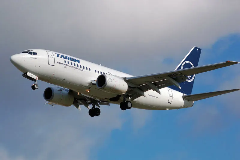
An airplane or aeroplane is a fixed-wing aircraft that is propelled forward by thrust from a jet engine, propeller, or rocket engine. Airplanes come in a variety of sizes, shapes, and wing configuration. The broad spectrum of uses for airplanes includes transportation of goods and people, military, and research. Worldwide, commercial aviation transports more than four billion passengers annually on aieliners and transports more than 200 billion tonne-kilometers of cargo annually, which is less than 1% of the world's cargo movement. Most airplanes are flown by a pilot on board the aircraft, but some are designed to be remotely or computer-controlled such as drones. Weight of Landplane aircraft is dependent on size of aircraft and uses of aircraft. Antanov AN-225 model aircraft maximum gross takeoff weight is 640000 Kg.
2.1.1.3. Seaplane:
2.1.1.3.1. Float Plane:
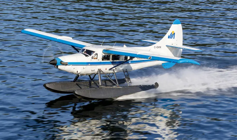
A floatplane is a type of seaplane with one or more slender floats mounted under the fuselage to provide buoyancy. By contrast, a flying boat uses its fuselage for buoyancy. Either type of seaplane may also have landing gear suitable for land, making the vehicle an amphibious aircarft. Maximum weight of Floatplane is 1008 Kg.
2.1.1.3.2. Flying Boat:
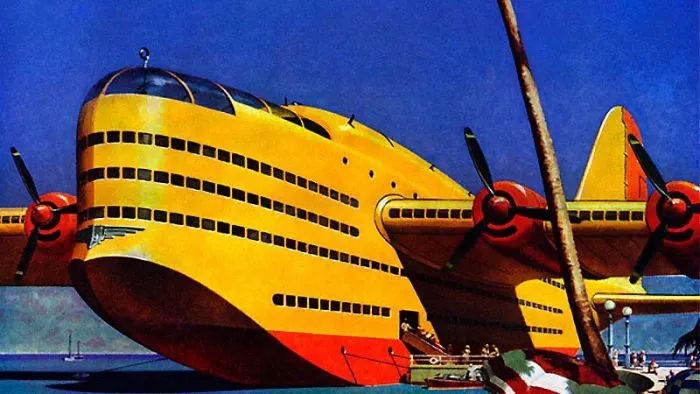
A flying boat is a fixed-winged seaplane with a hull, allowing it to land on water, that usually has no type of landing gear to allow operation on land. It differs from a floatplane as it uses a purpose-designed fuselage which can float, granting the aircraft buoyancy. Flying boats may be stabilized by under-wing floats or by wing-like projections from the fuselage. The maximum weight of a flying boat is 762 Kg.
2.1.2. Rotary Wing Aircraft:
2.1.2.1. GyroPlane:
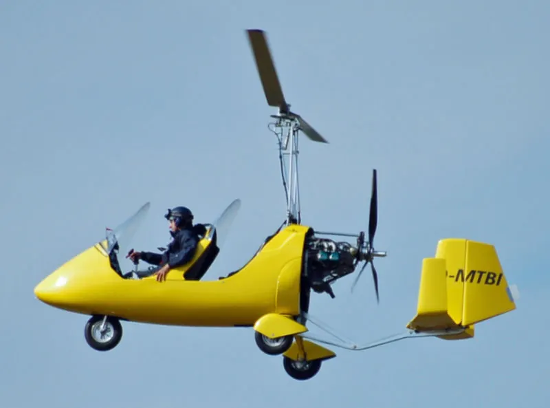
A gyroplane also known as an autogyro or gyrocopter, is a type of rotorcraft that uses an unpowered rotor in free autorotationto develop lift. Forward thrust is provided independently, by an engine-driven propeller. While similar to a helicopter rotor in appearance, the autogyro's rotor must have air flowing across the rotor disc to generate rotation, and the air flows upwards through the rotor disc rather than down. Maximum gross weight of a gyroplane is 560 Kg.
2.1.2.2. Helicopter:
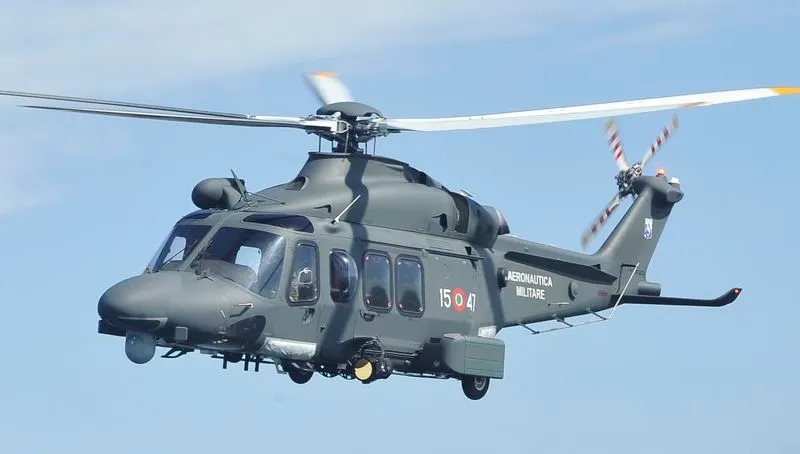
A helicopter is a type of rotorcraftin which lift and thrust are supplied by horizontally-spinning rotors. This allows the helicopter to take off and land vertically, to hover, and to fly forward, backward and laterally. These attributes allow helicopters to be used in congested or isolated areas where fixed-wing aircraft and many forms of VTOL (Vertical TakeOff and Landing) aircraft cannot perform. The maximum gross weight of a helicopter is 11200 Kg.
2.1.3. Ornithopter:
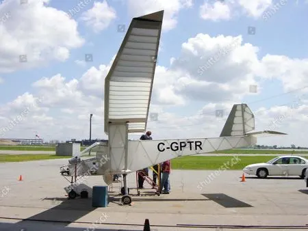
An ornithopter is an aircraft that files by flapping its wings. Designers seek to imitate the flapping-wing flight of birds, bats, and insects. Though machines may differ in form, they are usually built on the same scale as these flying creatures. Manned ornithopters have also been built, and some have been successful. The machines are of two general types: those with engines, and those powered by the muscles of the pilot.
2.2. Without Engine:
2.2.1. Glider (sailplane):
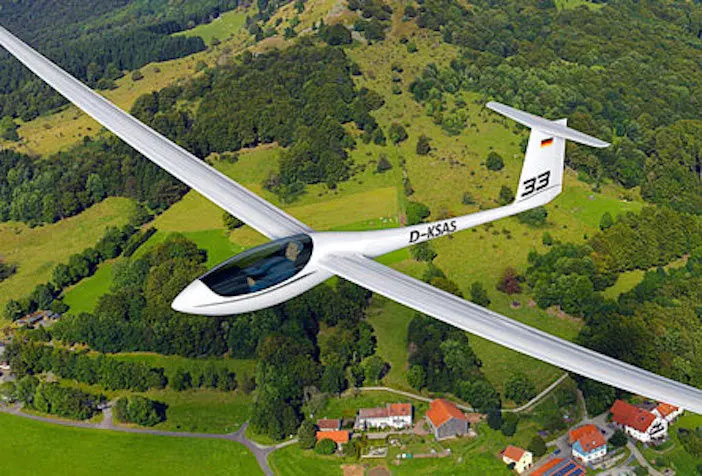
A glider or sailplane is a type of glider aircraft used in the leisure activity and sport of gliding (also called soaring). This unpowered aircraft can use naturally occurring currents of rising air in the atmosphere to gain altitude. Sailplanes are aerodynamically streamlined and so can fly a significant distance forward for a small decrease in altitude. Gliders can range from an empty weight of 60 Kg, to a maximum weight of almost 907 Kg.
2.2.2. Kite or Unpowered Aircraft:
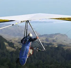
Kite or Unpowered aircraft can remain airborne for a significant period of time without onboard propulsion. They can be classified as fixed-wing glider, lighter-than-air balloon and tethered kites. This requires a trajectory that is not merely a vertical descent such as a parachute. Wright brother unpowered aircraft weighted about 23 Kg without the pilot, and 90 Kg with the pilot.
Q. 2. Is there any difference between ground speed and air speed?
Ans.
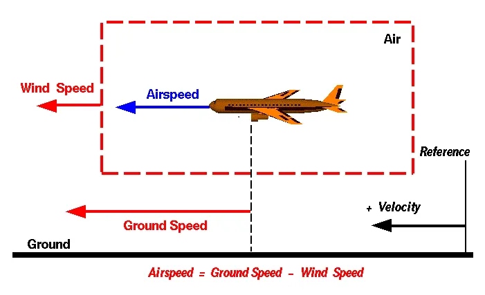
Ground Speed:
Ground speed is the aircraft’s speed relative to the ground. One thing that should be noted here is that it’s its horizontal rather than vertical speed – an aircraft climbing completely vertically would have a ground speed of zero.
Air Speed:
Airspeed is simply the speed at which an aircraft is moving relative to the air it is flying in. As such, it’s also the speed at which the air is flowing around the aircraft’s wings.
Wind’s Effects on Ground Speed and Airspeed:
The relationship between airspeed and ground speed is fairly simple. Ground speed is simply the sum of airspeed and wind speed.
If the aircraft is flying in the same direction as the wind is blowing, the aircraft experiences tailwind and it is considered as a positive wind, that time its ground speed is higher than its airspeed. On the other hand, if the wind is blowing against the direction the aircraft is traveling in, the aircraft experiences headwind and it is considered as a negative wind, that time its ground speed is lower than its airspeed.
Airspeed = Ground Speed - Wind Speed
Examples:
Suppose we had an airplane that could take off on a windless day at 100 mph (liftoff airspeed is 100 mph). We are at an airport with an east-west runway that is 1 mile long. The wind is blowing 20 mph towards the west and the airplane takes off going east. The wind is blowing towards the aircraft which we call a headwind. Since we have defined a positive velocity to be in the direction of the aircraft's motion, a headwind is a negative velocity. While the plane is sitting still on the runway, it has a ground speed of 0 and an airspeed of 20 mph:
Airspeed = Ground Speed (0) - Wind Speed (-20) = 20 mph
Let's assume that now the airplane is flying at 5000 feet down the runway, the velocity is 80 mph. Then the airspeed is given by:
Airspeed = Ground Speed (80) - Wind Speed (-20) = 100 mph
Now another pilot, with exactly the same airplane, decides to take off to the west. The wind is now in the same direction as the motion and this is called a tailwind. The sign on the wind speed is now positive. The acceleration along the ground is the same, so at 5000 feet down the runway, the ground speed is again 80 mph. The airspeed is then given by:
Airspeed = Ground Speed (80) - Wind Speed (20) = 60 mph
Q. 3. Why is it not recommended to use aircraft engine power to move it on the ground at Airport?
Ans.
Aircraft move using their own engine power all the time on the airport apron and taxiways under their own power to go towards runways and after landing taxi to their assigned gate. The only time they use external assistance is to pushback from the gate. Large turbofan aircraft need help to reverse via a pushback tractor. The engines are turned on after the pushback is complete and the aircraft can move forward under Its own power.
To be accurate, some aircraft can reverse using a variable pitch prop or thrust reversing on turbofans but generally reversing is done via pushback tractors. Blasting jet reversers blow debris in the crowded gate area creating foreign object damage hazard for adjacent aircraft, gate equipment or terminal waiting area glass windows.
That's why using aircraft engine power to move it on the ground at the airport is not recommended because of the risks which may arise from engine ground running related to the potential for loss of control of the aircraft by those persons occupying the pilot seats in the flight deck. The consequences of loss of control during taxi or towing are the same as apply to these operations. Unwanted consequences from such static running are mainly related to those arising from the unintended movement of the aircraft during engine running - effectively a loss of control - especially during high power engine running. Damage can occur to the aircraft itself, other aircraft nearby or to airside structures. In addition, there is a risk of injury to ground support personnel who may be in relatively close proximity to the aircraft.
Q. 4. How an aircraft is pushed to runway when its ready to take off?
Ans.
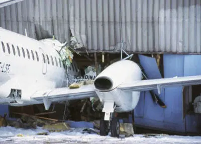
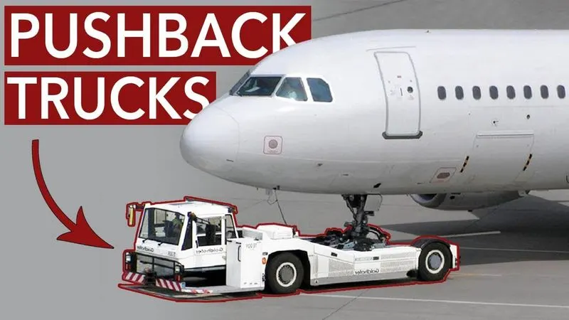
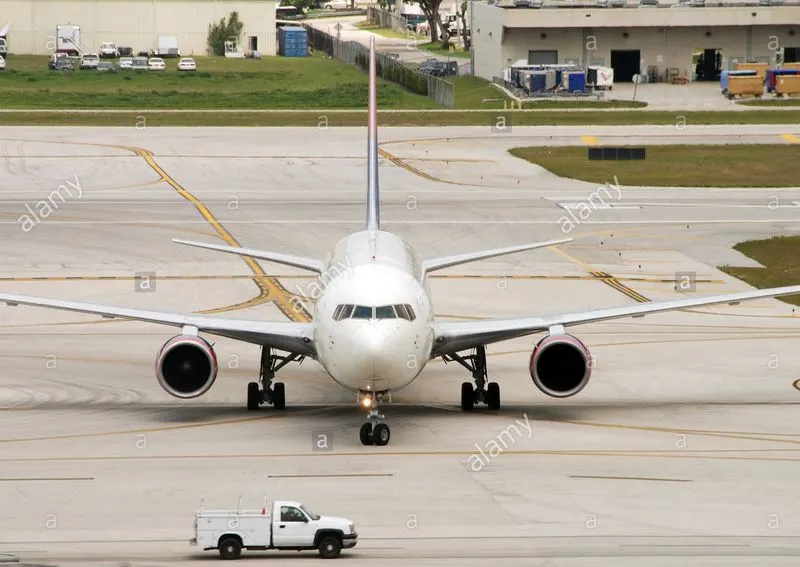
Airplanes have engines, and they can use them to move forward along the ground. So they push themselves to the runway. In some cases a small vehicle is needed to push the airplane backwards away from the terminal building, because even if a plane can reverse it’s thrust, it’s not always safe to hit the buildings with a jet blast. So the little trucks push the jets back away from the buildings is called a pushback.And old aircraft can not reverse themselves that time they use pushback tractors. After pushback aircraft move itself on taxiways to reach the runway is called taxiing.
Pushback is when an aircraft is pushed backwards away from the airport gate by vehicles called tugs or tractors.
Taxiing is the movement of an aircraft on the ground, under its own power. An airplane uses taxiways to taxi from one place in an airport to another; for example, when moving from an aircraft hanger to the runway.
Q. 5. Learn about take off power, tyre design, rolling resistance, tyre pressure, brake forces when landing.
Ans.
Take Off Power:
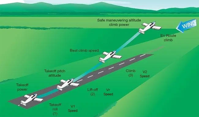
On take-off, in order to position the aircraft to a safe height away from terrain and obstacles (i.e. a flight path of maximum height and minimum ground distance desired), the engine thrust is set to a high ‘take-off power’ setting (although this is not necessarily full power) and the aircraft attitude is pitched up to maintain a specific speed (usually in the region of V2 + 28 Kmph). Once the ‘safe height’ is reached the engine thrust can therefore be reduced to a more appropriate (i.e. efficient) setting and the aircraft flight path can be changed to a more appropriate (i.e. efficient) flight path.
In order to achieve that described above and also to provide minimum noise disturbance to the area surrounding the airport, regulatory procedures require aircraft to fly one of the two profiles given below during every departure. The aerodrome briefing pages will state which one of the two profiles is to be flown at each particular airport:
- At 1,500ft aal reduces thrust to climb power and accelerate the aircraft towards 463 Kmph, retracting flaps and slats.
- At 1,500ft aal reduces thrust to climb power maintaining V2 + 28 Kmph. At 3,000ft accelerate the aircraft.
Tire Design:
When it comes to safety, tyres are one of the most important components of aircraft. They help to absorb the shock of landing and provide cushioning. It also provides the necessary traction for braking and stopping of an aircraft.
An aircraft tyre is designed to withstand extremely heavy loads while landing, take off, taxing, and parking. The number of wheels required for aircraft increases with the weight of the aircraft, as the weight of the aeroplane needs to be distributed more evenly.
Designing aircraft tires is a very intense undertaking. Once an aircraft manufacturer goes to the tire manufacturer with the size and weight requirements, the tire manufacturer begins the process of designing a tire that meets the needs of the aircraft manufacturer as well as all regulatory requirements — including foreign regulations in many cases.
Engineers are challenged with designing tires with cool running, heat-resistant materials while simultaneously exceeding tire service requirements. Tire prototypes are put through rigorous tests that simulate cycles of landings, take-offs, and taxi operations. It is only after the tires pass all mandatory tests and meet the requirements of the aircraft manufacturer and airworthiness authorities that the tires are put into production.
Types of Tire:
1. Bias-ply tire construction:
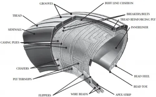
Bias-ply tires are popular choices for aircraft tires because of their durability and retreadability. The tire construction consists of the following components:
Tread: The tread is made of rubber mixed with other additives to obtain the desired level of toughness, durability, and resistance to wear. The tread pattern is designed to aircraft operational requirements, with the ribbed tread design used widely due to its good traction under varying runway conditions.
Sidewall: The sidewall is a protective layer of rubber that covers the outer casing ply. It extends from the tread edge to the bead area.
Tread Reinforcing Ply: One or more layers of fabric that strengthens and stabilizes the tread area for high-speed operation. It also serves as a reference for the buffing process when tires are retreaded.
Buff Line Cushion: The buff line cushion is made of rubber compound to enhance the adhesion between the tread reinforcing ply and the breakers or casing plies. It is of sufficient thickness to allow for the removal of the old tread when the tire is retreaded.
Breakers: Breakers are reinforcing plies of rubber-coated fabric placed under the buff line cushion to protect casing plies and strengthen and stabilize the tread area. They are considered an integral part of the casing construction.
Casing Plies: Alternate layers of rubber-coated fabric (running at opposite angles to one another) provide the strength of the tire.
Wire Beads: Hoops of high tensile strength steel wire that anchor the casing plies and provide a firm mounting surface on the wheel. The outer edge of the bead that fits against the wheel flange is called the bead heel. The inner bead edge is called the bead toe.
Apex Strip: A wedge of rubber affixed to the top of the bead bundle.
Flippers: Layers of rubberized fabric that help anchor the bead wires to the casing and improve the durability of the tire.
Ply Turnups: The casing plies are anchored by wrapping them around the wire beads, thus forming the ply turnups.
Chafer: A protective layer of rubber and/or fabric located between the casing plies and wheel to minimize chafing.
Liner: In tubeless tires, the liner is a layer of low permeability rubber that acts as a built-in tube and restricts gas from diffusing into the casing plies. In tube-type tires, a thinner liner is used to prevent tube chafing against the inside ply.
2. Radial-ply tire construction:
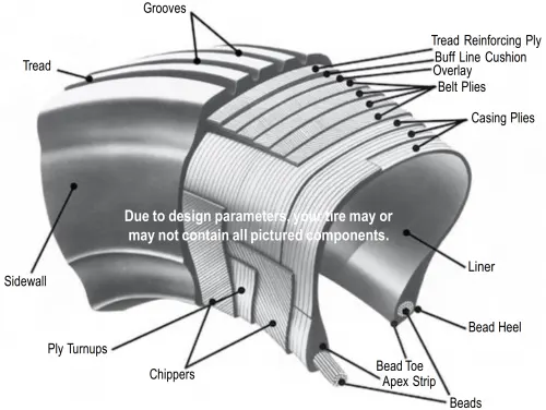
A typical radial tire is illustrated in Figure 2. With their rigid belt, they provide increased landings and reduced rolling resistance. They have fewer components in their construction and are lighter than similarly sized bias ply tires. Components that differ from bias-ply construction as follows:
Overlay: A layer of reinforcing rubber coated fabric placed on top of the belts to aid in high speed operation.
Belt Plies: A composite structure that stiffens the tread area for increased landings. The belt plies increase the tire strength in the tread area.
Casing Plies: As in bias-ply tires, the casing plies are layers of rubber-coated fabric. However, unlike those in bias plies that run at opposite angles to one another, radial plies run radially from bead to bead.
Chippers: The chippers are layers of rubber-coated fabric applied at diagonal angles that improve the durability of the tire in the bead area.
Rolling Resistance:
1. Flight-Test Method:
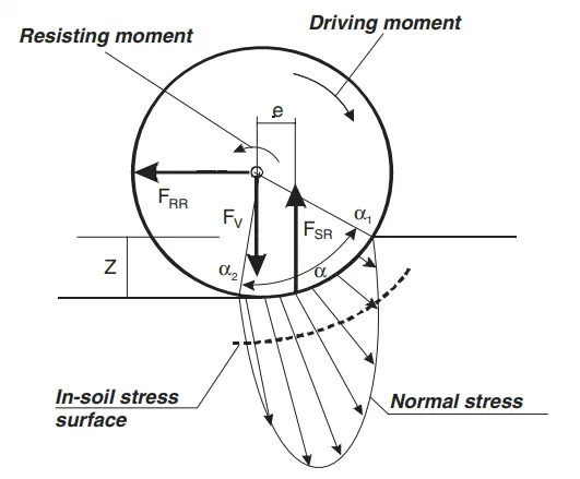
This method can be used for identification of rolling resistance coefficients at a full range of speeds during a takeoff run. In this method, an instrumented aircraft was test flown on an unsurfaced airfield to gather experimental data needed for further calculations of rolling resistance.
2. Soil Stress and Deformation Method:
Rolling resistance due to deformation of the airfield surface at low speed has to be determined with respect to soil response to the applied wheel load. A method proposed by the author is to determine soil stress and deformation under aircraft wheel loads and then to determine the coefficients of resistance based on the obtained experimental data.
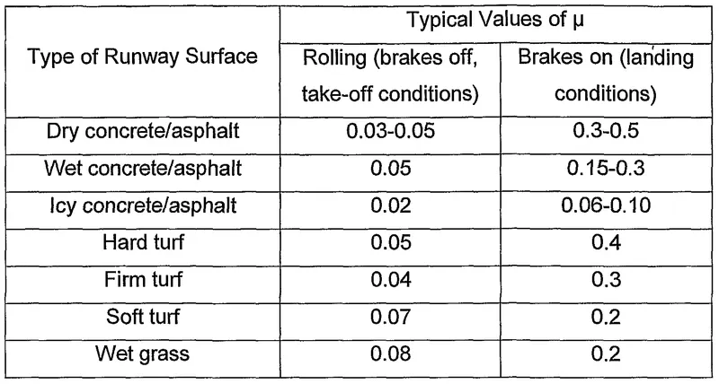
Below figure shows some runway surfaces and its rolling resistance coefficient.
Tire Pressure:
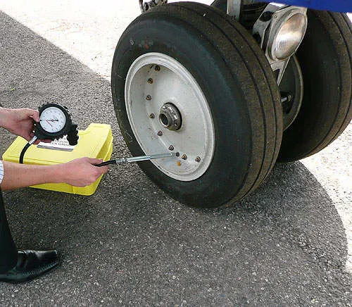
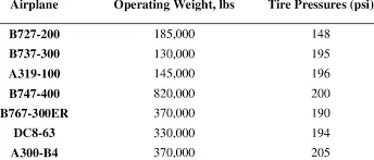
An aircraft tire or tyre is designed to withstand extremely heavy loads for short durations.[1] The number of tires required for aircraft increases with the weight of the aircraft, as the weight of the airplane needs to be distributed more evenly.
The high-flying rubber is typically inflated to 200 psi, roughly six times what you put in an automobile tire, and the tires on an F-16 fighter are pumped to 320 psi. “It's really pressurized air that's so strong
Brake Force when Landing:
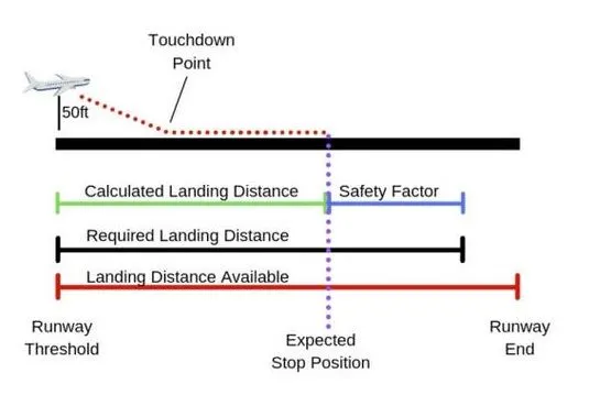
Bringing aircraft down to the runway from 37,000 feet is only part of the challenge. It’s not over until the aircraft is safely parked at its gate. In order to do this, pilots have a number of systems available to slow the aircraft down
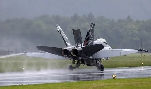
Stopping a 200-tonne aircraft landing at 180 mph requires a lot of braking force. To do this, the 787 has one brake unit on each of the eight wheels on the main gear assembly. On other aircraft types, the brake units are powered by the hydraulics or electric system. An electrical signal is sent from the flight deck to hydraulic or electric actuators near the main landing gear. Here, a hydraulic fluid or electric brake controller at 3,000 pound per square inch is used to force the brake unit against the wheel, thus slowing it down.
There are other braking systems also available for helping to slow down the aircraft when landing like spoiler, reverse thrust. Similarly there is another system also available to enhance the braking system safety like Anti-skid protection, parking brake, Auto brake and Brake temperature indication.
Q. 6. A. With necessary assumptions, calculate the force and power required to push / pull an aircraft by a towing vehicle.
Ans.
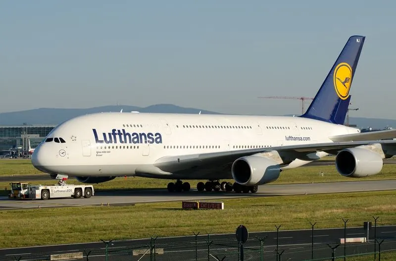
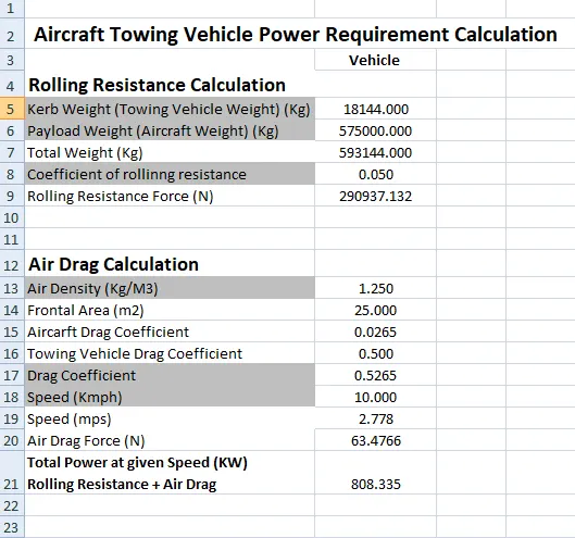
Let's assume we calculate the force and power of the towing vehicle when the vehicle tow the Airbus A380 aircraft.
Assumption:
Air density (⍴) = 1.25 Kg/m^3
Drag coefficient of towing vehicle (Cd1) = 0.5
Drag coefficient of aircraft (Cd2) = 0.0265
Total drag coefficient (Cd) = (0.5+0.0265) = 0.5265
Total frontal area (A) = 25 m^2
Rolling Resistance on dry concrete (μrr) = 0.05
Weight of Airbus A380 aircraft = 575000 Kg
Weight of towing vehicle = 18144 Kg
Total Weight (m) = 575000 + 18144 = 593144 Kg
Maximum Speed of towing vehicle (V) = 10 Kmph = 2.78 m/sec
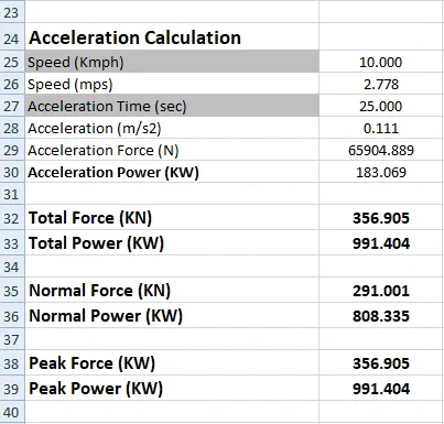
Acceleration time (t) = 25 sec
Acceleration (a) = V/t = 0.1112 m/sec^2
Total tractive force for towing the aircraft when acceleration is 0.1112 m/sec^2 and reaching maximum speed.
Force = Fad + Frr + Fla + Fhc
Hill climbing force is zero at the airport because the airport is flat.
Force = (0.5*⍴*A*Cd*V^2) + (μrr*m*g) + (m*a)
Force = (0.5*1.25*25*0.5265*2.78^2) + (0.05*593144*9.81) + (593144*0.1112)
Force = 63.578 + 290937.132 + 65957.6128
Force = 356.958 KN
Total tractive force for towing the aircraft when towing vehicles run at maximum speed 10Kmph after acceleration. Now the acceleration force is zero and hill climbing force is also zero.
Force = Fad + Frr
Force = (0.5*⍴*A*Cd*V^2) + (μrr*m*g)
Force = (0.5*1.25*25*0.5265*2,78^2) + (0.05*593144*9.81)
Force = 63.578 + 290937.132
Force = 291KN
Now we calculate power,
Power = Force * Velocity
Total tractive power for towing the aircraft when acceleration is 0.1112 m/sec^2 and reaching maximum speed.
Peak Power = 356.958*2.78 = 992.343 KW
Total tractive power for towing the aircraft when towing vehicles run at maximum speed 10Kmph after acceleration.
Normal Power = 291*2.78 = 808.98 KW
The force and power required to push / pull an aircraft by a towing vehicle: Force is 291KN, Peak Force is 356.958 KN, Normal Power is 808.98 KW and Peak Power is 992.343 KW.
B. Develop the model for the calculated force and power using Simulink.
Ans.
Model:
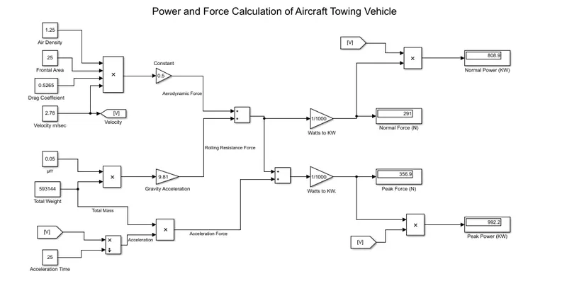
- We can see that the above figure shows the model of power and force calculation of aircraft towing vehicle. In this model I used a constant block and some math function block and created a model.
- For this model I took the same variable parameters which were used in the previous question and got the same result as the previous result.
- In this model I used a constant block for variable parameters. We can change the variable parameters and determine power and force as per our towing vehicle and aircraft.
- Attach the model file for reference name as ‘Aircraft_Towing_Vehicle_calculation.slx’.
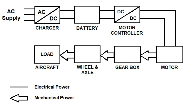
Q. 7. A. Design an electric powertrain with type of motor, it’s power rating, and energy requirement to fulfill aircraft towing application in Simulink. Estimate the duty cycle range to control the aircraft speed from zero to highest. Make all required assumptions. Prepare a table of assumed parameters. Draw a block diagram of powertrain.
Ans.
Assumption:
|
Parameters |
Value |
|
Maximum Vehicle speed |
2.78 m/sec |
|
Motor Type |
Permanent Magnet DC Motor |
|
Motor Output Power |
850 KW |
|
Motor Rated Voltage |
500 V |
|
Rated Speed (at rated load) |
220 rpm |
|
No Load Speed |
300 rpm |
|
Rotor Inertia |
0.0002 Kg*m^2 |
|
Wheel Radius |
0.5 m |
|
Mass (Towing Vehicle + Aircraft) |
593144 Kg |
|
Gear ratio |
4 |
|
Supply Input Voltage (DC Voltage) |
500 V |
|
Required Power |
809 KW |
|
Peak Required Power |
993 KW |
|
Maximum Speed Requirement |
53 rpm |
|
Maximum Torque Requirement |
178.479 KNm |
Block Diagram of Powertrain:
Model:
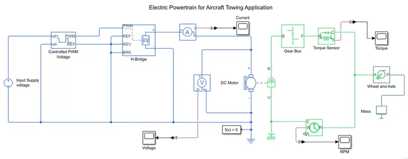
- We can see that I created a model for an aircraft towing vehicle with the help of a H-bridge circuit and controlled PWM voltage blocks.
- For propulsion I used a DC type permanent magnet motor of 500V, 850 KW output power at 300 rpm no load speed.
Result:
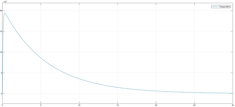
- In the figure below we can see the torque produced by the motor as per our requirement.
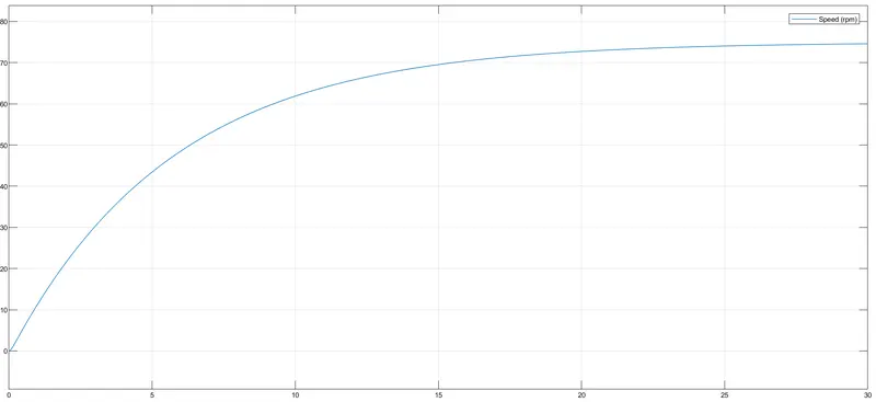
- Similarly we can see the below figure speed of vehicle in rpm.
- Attached a simulink file for reference name as ‘Aircraft_Towing_tractor.slx’.
B. Also, Design the parameters in excel sheet.
Ans.
- Below figure we can see that I determine the parameters value which are required to push/pull the aircraft for towing tractor with the help of excel sheet.
- Attach the excel sheet for the reference name as ‘Towing tractor calculation’.