Week-6 Challenge: EV Drivetrain
Q. 1. Which types of power converter circuits are employed in electric and hybrid electric vehicle?
Ans.
Normally there are 4 types of converter based on change in power source voltage level.
- AC to DC Converter (Rectifier)
- DC to AC Converter (Inverter)
- DC to DC Converter (Chopper)
- AC to AC Converter (Regulator)
But in electric and hybrid electric vehicles mostly three types of converter are used.
1.AC to DC Converter: (AC Charger)
When we charge the vehicle on AC power supply we require AC to DC charger i.e. charger because input supply is AC and we store energy in a battery which is a DC storage system. But when we charge the vehicle on a DC power supply we do not require an AC to DC converter. Now the charger is one direction but in future or in case we connect the vehicle to the grid that time we require a bidirectional charger.
2. DC to AC Converter: (Inverter or Motor Controller)
When we use an AC motor for propulsion of a vehicle then only we require DC to AC converter for converting battery DC power to AC power which used to run the AC motor. This converter is inbuilt in a motor controller and it is bidirectional because when regenerative braking starts that time motor acts as a generator and feeds the power to the battery.
3. DC to DC Converter: (Chopper)
These converter only change the voltage level. Our vehicle auxiliary component operates on low voltage and our vehicle battery pack voltage is high. Therefore we used the chopper to fulfill the auxiliary component voltage requirement. If our vehicle runs on a low voltage battery pack and the auxiliary component also operates on the same voltage then we do not require a chopper. Normally in the market mostly bidirectional chopper is available but we do not require specifically bidirectional chopper, one directional chopper is enough for our case.
Q. 2. An Electric Vehicle's powertrain with 72V battery pack in shown in the diagram below. The duty ratio for acceleration operation is 'd1' and for the braking operation the duty ratio is 'd2'. What is EV steady state speed if duty cycle is 70%?
Ans.
The other parameters of the electric vehicle is given below,
Motor and Controller Parameters:
Rated Armature voltage= 72 V
Rated armature current= 400 A
Ra= 0.5Ω, KΦ= 0.7 Volt second
Chopper Switching frequency= 400 Hz
The vehicle speed-torque characteristics are given by the below equation
Tv = 24.7 + (0.0051)*⍵^2
When d = 70%
Input Voltage = Battery Pack Voltage * Duty Cycle = 72*0.7 = 50.4 V
Angular Speed Equation,
⍵ = (V/KΦ) - Ra*T/(KΦ)^2
⍵ = 50.4/0.7 - 0.5*(24.7 + (0.0051)*⍵^2)/0.7^2
⍵ = 72 - (12.35 - 0.00255*⍵^2)/0.49
⍵ = (35.28 - 12.35 - 0.00255*⍵^2)/0.49
⍵ = (22.93 - 0.00255*⍵^2)/0.49
0.00255*⍵^2 + 0.49⍵ - 22.93 = 0
By Solving above quadratic equation,
When d1 = 70% (Acceleration Mode)
⍵ = 38.91 rps = 2334.6 rpm
When d2 = 70% (Braking Mode)
⍵ = 231.071 rps = 13864.26 rpm
EV steady state speed if duty cycle is 70% in motoring mode is 2334.6 rpm and regenerative mode 13864.26 rpm.
Q. 3. Develop a mathematical model of a DC Motor for the below equation using Simulink. ⍵ = V/KΦ - Ra/(KΦ)^2*T
Ans.
Angular Speed of DC Motor:
⍵ = V/KΦ - Ra/(KΦ)^2*T
Where,
⍵ = Angular Speed in rpm
V = Input Voltage V
KΦ = Motor Constant
Ra = Armature Resistance in ohm
T = Motor Torque in Nm
For this equation simulation model I used four constant blocks for input data as input voltage V, Motor Constant KΦ, Armature Resistance Ra, Torque T. And created a model as per shown in below figure with the help of math function blocks and display blocks.
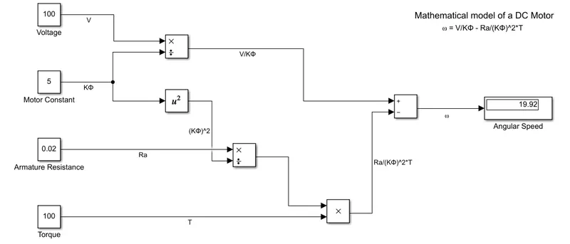
I got 19.92 rpm angular speed when 100 V input voltage, motor constant is 5, armature resistance is 0.02 ohm and torque is 100 Nm.
Also I attach simulation model file name as ‘Q3_mathematical_model.slx’
Q. 4. Refer to the blog on below topic. Explain in brief about author’s perspective.
Ans.
In this blog author’s compare the Brushless DC motor (BLDC) with the Induction motor and try to say that each will have its loyal proponents and religious detractors in all streams if there is an engine vehicle, gas vehicle or electric vehicle.
In BLDC motor use permanent magnet as a rotor that why it give some benefits like simple in control, its achieve good performance in torque, peak efficiency is high and in other hand some limitation also have like, permanent magnets are expensive it's essentially required motor controller, it can not adjust the magnetic field B and also if increase the size of motor then magnetic losses also increase.
In Induction motor there is no permanent magnet used in the rotor. That is why in this we will adjust the magnetic field B and magnetic losses also less than BLDC motor, no inverter circuit mandatory required. But on the other hand control is complex, not meeting the torque requirement without an inverter circuit. With inverter circuit (without feedback loop) torque increases but even less than the BLDC motor, when we give feedback loop with inverter circuit then induction motor competing with BLDC motor.
Both BLDC and induction drives use motors having similar stators. Both drives use 3-phase modulating inverters. The only differences are the rotors and the inverter controls. BLDC motor operate in unity power factor, produce less heat and peak efficiency is high. On the other hand Induction motor operate in 0.85 power factor, produce high heat and average efficiency id high.
Author’s not conclude which motor is better in both of these. They mention in conclusion that BLDC drives will likely continue to dominate in the hybrid and plug-in hybrid markets, and that induction drives will likely maintain dominance for the high-performance pure electrics.