Project-1: Modelling an electric Car with Li-ion battery
Aim: Create a MATLAB model of electric car with lithium ion battery and suitable motor.
Objective:
- Run the electric car model and determine the energy consumption, observe the vehicle performance.
- System convert non-linearization to linearization on transfer function based (PID tuner app).
- Change the PI controller value and observe the vehicle behavior.
Electric Car:
An electric car or battery electric car is an automobile that is propelled by one or more electric motors, using energy stored in batteries. Compared to internal combustion engine (ICE) vehicles, electric cars are quieter, have no exhaust. Overall ownership is cheaper than that of equivalent ICE cars, due to higher efficiency, lower fueling and maintenance costs. Charging an electric car can be done at a variety of charging stations. These charging stations can be installed in both houses and public areas.
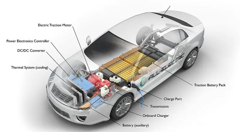
Key Component of Electric Car:
Electric traction motor:
Using power from the traction battery pack, this motor drives the vehicle's wheels. Some vehicles use motor generators that perform both the drive and regeneration functions.
Traction battery pack:
Stores electricity for use by the electric traction motor.
Power electronics controller:
This unit manages the flow of electrical energy delivered by the traction battery, controlling the speed of the electric traction motor and the torque it produces.
Onboard charger:
Takes the incoming AC electricity supplied via the charge port and converts it to DC power for charging the traction battery. It also communicates with the charging equipment and monitors battery characteristics such as voltage, current, temperature, and state of charge while charging the pack.
Charge port:
The charge port allows the vehicle to connect to an external power supply in order to charge the traction battery pack.
DC/DC converter:
This device converts higher-voltage DC power from the traction battery pack to the lower-voltage DC power needed to run vehicle accessories and recharge the auxiliary battery.
Thermal system (cooling):
This system maintains a proper operating temperature range of the engine, electric motor, power electronics, and other components.
Transmission (electric):
The transmission transfers mechanical power from the electric traction motor to drive the wheels.
Battery (all-electric auxiliary):
In an electric drive vehicle, the auxiliary battery provides electricity to power vehicle accessories.
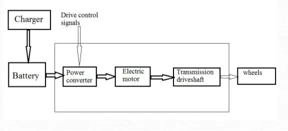
Block Diagram of Electric Vehicle:
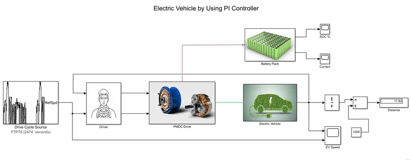
Simulink Model:
Drive Cycle: FTP75

The FTP cycle (for Federal Test Procedure) has been created by US EPA (Environmental Protection Agency) to represent a commuting cycle with a part of urban driving including frequent stops and a part of highway driving.
Drive Cycle Characteristic:
- Duration: 2474 sec
- Distance: 17.77 Km
- Average Speed: 34.12 Kmph
- Maximum Speed: 91.25 Kmph
PI Controller:
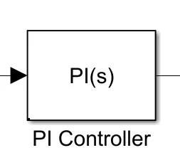
This block implements continuous- and discrete-time PID control algorithms and includes advanced features such as anti-windup, external reset, and signal tracking. We can tune the PID gains automatically using the 'Tune...' button (requires Simulink Control Design).
PI Controller Parameters:
- Proportional(P) Value: 0.4167
- Integral(I) Value: 0.05246
- Tuning Method: Transfer Function Based.
Saturation:
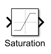
Limit input signal to the upper and lower saturation values.
Saturation block parameters:
- Upper limit for acceleration command: 5
- Lower limit for acceleration command: 0
- Upper limit for deceleration command: 0
- Lower limit for deceleration command: -5
H-Bridge Motor Controller:
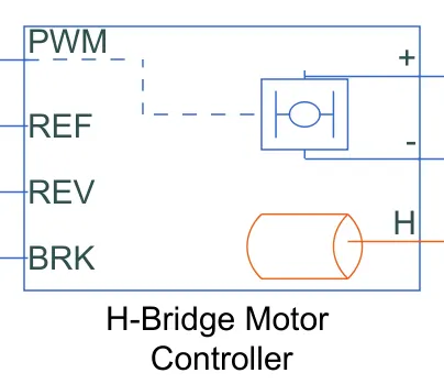
This block represents an H-bridge motor drive. The block can be driven by the Controlled PWM Voltage block in PWM or Averaged mode. In PWM mode, the motor is powered if the PWM port voltage is above the Enable threshold voltage. In Averaged mode, the PWM port voltage divided by the PWM signal amplitude parameter defines the ratio of the on-time to the PWM period. Using this ratio and assumptions about the load, the block applies an average voltage to the load that achieves the correct average load current. The Simulation mode parameter value must be the same for the Controlled PWM Voltage and H-Bridge blocks. H port is a thermal port.
H-bridge motor controller parameters:
- Output Voltage Amplitude: 330 V
Controlled PWM Voltage:
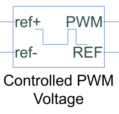
This block creates a Pulse-Width Modulated (PWM) voltage across the PWM and REF ports. The output voltage is zero when the pulse is low, and is equal to the Output voltage amplitude parameter when high. Duty cycle is set by the input value.
Permanent Magnet DC Motor: (PMDC Motor)
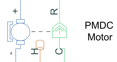
The block assumes that no electromagnetic energy is lost, and hence the back-emf and torque constants have the same numerical value when in SI units. Motor parameters can either be specified directly, or derived from no-load speed and stall torque. If no information is available on armature inductance, this parameter can be set to some small non-zero value. H port is a thermal port for measuring the temperature.
PMDC Motor Parameters:
- No Load Speed: 7000 rpm
- Rated Speed (at rated load): 5000 rpm
- Rated Load (Mechanical Power): 75 KW
- Rated DC Voltage Supply: 330 V
Simple Gear:
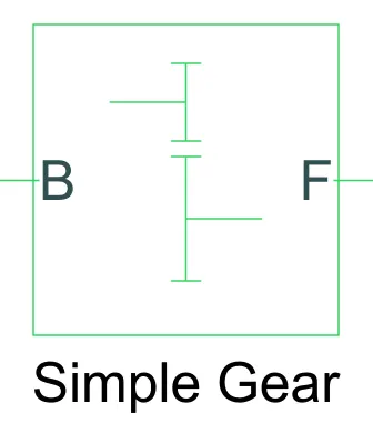
The Simple Gear block represents a gearbox that constrains the connected driveline axes of the base gear, B, and the follower gear, F, to corotate with a fixed ratio that you specify. You choose whether the follower axis rotates in the same or opposite direction as the base axis. If they rotate in the same direction, the angular velocity of the follower, ωF, and the angular velocity of the base, ωB, have the same sign. Follower (F) to base (B) teeth ratio is 2.
Vehicle Body:
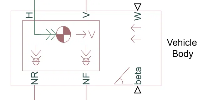
The Vehicle Body block represents a two-axle vehicle body in longitudinal motion. The vehicle can have the same or a different number of wheels on each axle. The vehicle wheels are assumed identical in size. The vehicle can also have a center of gravity (CG) that is at or below the plane of travel. The block accounts for body mass, aerodynamic drag, road incline, and weight distribution between axles due to acceleration and road profile.
Vehicle Body Parameters:
- Vehicle Mass: 1200 Kg
- Frontal Area: 3 m^2
- Drag Coefficient: 0.4
- Air Density: 1.25 Kg/m^3
Tire:
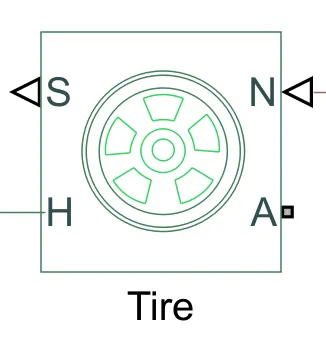
Represents the longitudinal behavior of a highway tire characterized by the tire Magic Formula. The block is built from Tire-Road Interaction (Magic Formula) and Simscape Foundation Library Wheel and Axle blocks. Optionally, the effects of tire inertia, stiffness, and damping can be included.
Tire Parameters:
- Rolling Radius: 0.3 m
Lithium-ion Battery:
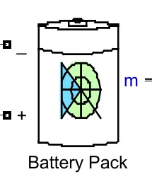
Implements a generic battery model for most popular battery types.
Battery Pack Parameters:
- Battery Type: Lithium-ion
- Nominal Voltage: 330 V
- Rated Capacity: 100 Ah
- Initial SOC (%): 100%
Driver:
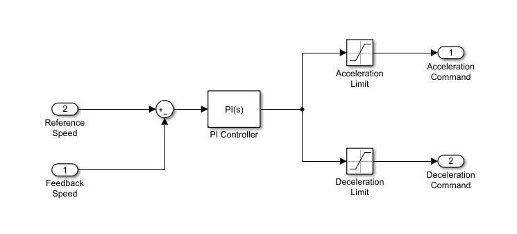
The above figure shows inside the Driver subsystem. In this subsystem, the PI controller generates acceleration and deceleration commands for our EV by using a saturation block. And for the PI controller, input signal provides the difference between reference speed signal and vehicle feedback speed signal.
PMDC Drive:
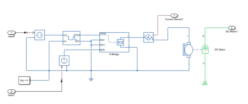
We can see that in the above figure inside the PMDC drive subsystem. For this system I give the acceleration and deceleration command and generate the motor output power connection to the next subsystem and similarly current value sent to the battery pack subsystem.
Electric Vehicle:
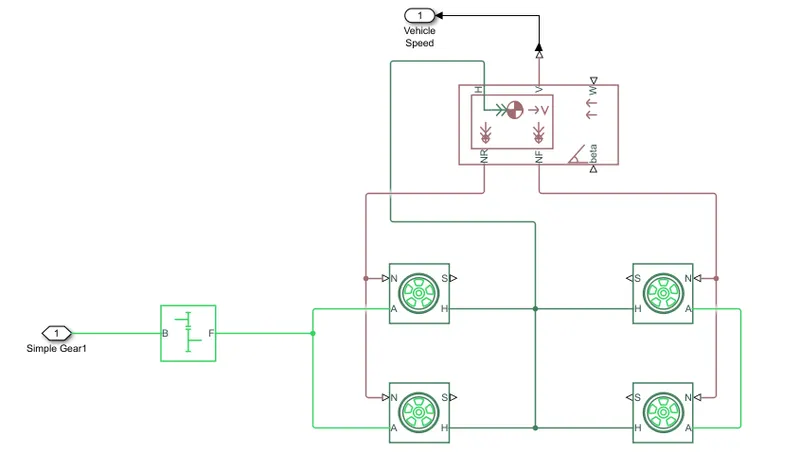
The above figure we can see that inside the electric vehicle subsystem. In this subsystem we determine the vehicle velocity.
Battery Pack:
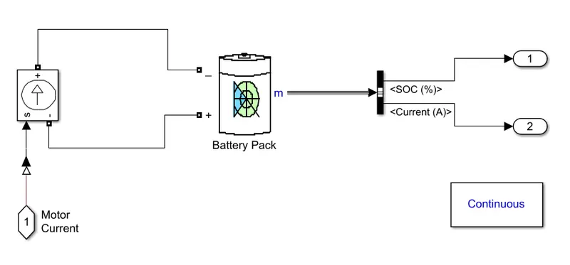
In the above figure we can see inside the Battery Pack subsystem. And in this subsystem we determine the battery pack SOC and battery current.
Let us now see how to systems are linearized, because our whole electric vehicle system is non-linear.
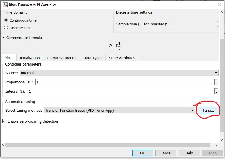
Initially our Proportional P value and Integral I value is 1. Now we try to tune the PI controller. In the above we start the tuning procedure by clicking the tune option.
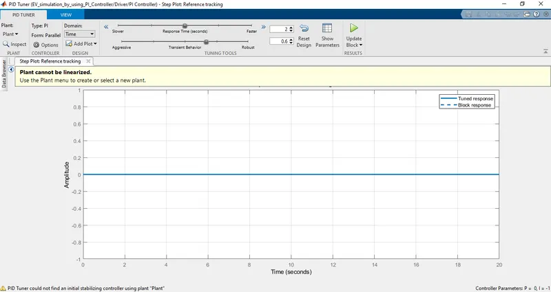
After clicking the tune option above the PID tuner window is open and in this we can see that our system is not linearized.
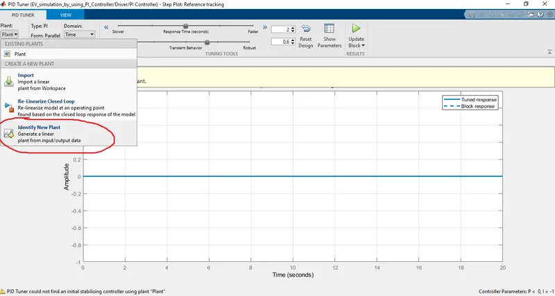
For plant linearization click on plant and select identify new plant.
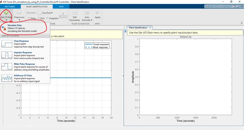
In the above we can see the plant identification on the right hand side. For obtaining input and output data click on get I/O data and select simulation data.
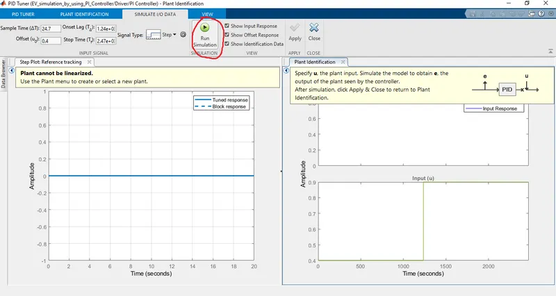
Now run the simulation.
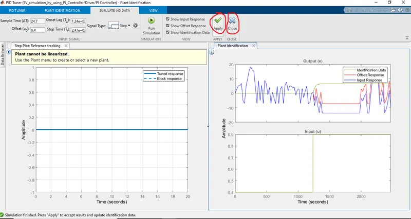
For applying input and output data click on the Apply and then close.
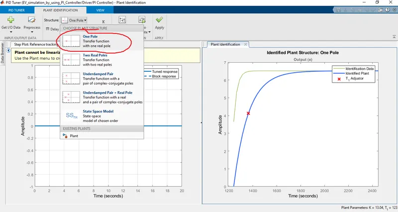
Now select one pole in the identified plant structure.
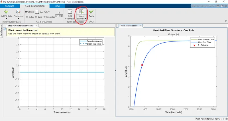
For applying one pole click on the auto estimate.
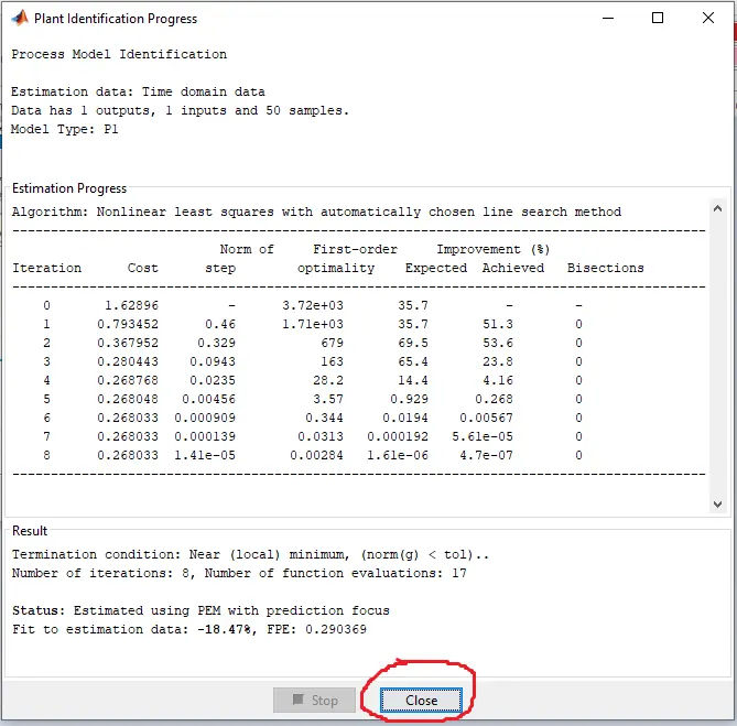
After clicking on auto estimate, the above window is open and estimated automatically. In our case it's estimated in 8 iterations.
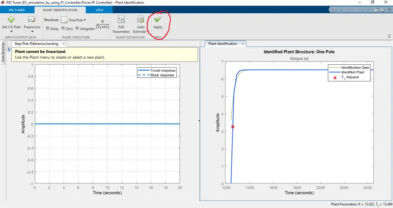
Click on apply, now our system is linearized.
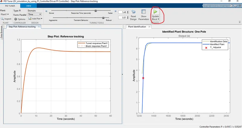
Now we can adjust the response time and transient behavior as per requirement and then click on the update block. Now it automatically update the PI controller block parameters.
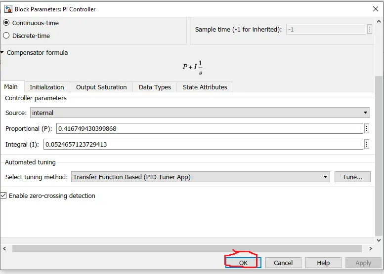
In the above figure we can see that the update the PI controller block parameters, after clicking on OK and it's ready to run the simulation.
Result:
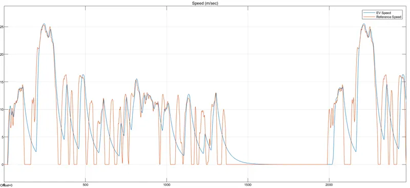
Electrical Car Speed
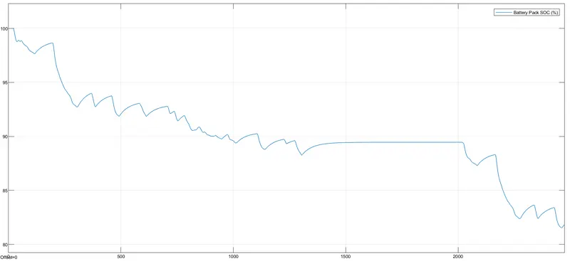
Battery Pack SOC
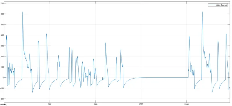
Motor Current
- The above figures show the various performance of electric cars. The first figure shows the car speed and it follows the drive cycle reference speed. This car travelled 17.82 Km.
- The second figure shows the battery pack SOC. After complete electric car simulation 81.87% battery is left. It means 6 KWh energy is required to travel 17.82 Km.
- In some time SOC increased due to the regenerative braking.
- The third figure shows the motor current, when current goes below zero it means regeneration starts.
Conclusion:
- We observe the performance of electric car at different controller values.
- We got the energy requirement to run on the drive cycle FTP75.