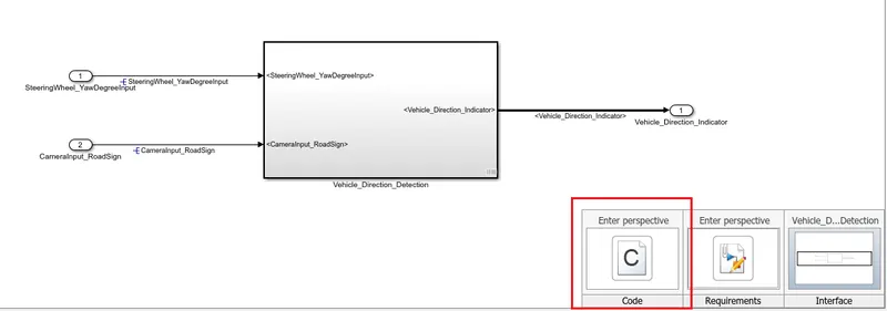
Project 1 (Mini Project on Vehicle Direction Detection
Aim: Create simulink Model for the Vehicle Direction Detection as per the requirement.
Objectives:
- Development of MATLAB Simulink model as per requirement.
- Tag the requirements to the simulink model; tagging requirement 1 & requirement 2 to their corresponding subsystems is fine.
- Make changes in model configuration for model based development, create a data dictionary, generate the code for simulation model.
Simulink Model:
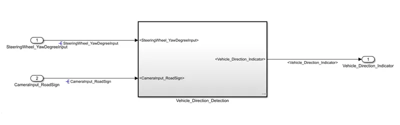
The above figure shows the simulink model for the Vehicle Direction Detection, in which two more subsystems are present. One subsystem for determining Vehicle turn status and another one is Vehicle Direction Indicator. The Vehicle Direction Detection subsystem gives two inputs as Steering Wheel Yaw Degree Input and Camera Input road Sign and these subsystems indicate the Vehicle Direction. Below figure shows the inside of these subsystems.
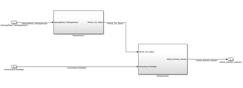
Requirement 1:
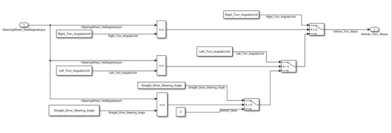
The above figure shows inside the Requirement 1, in this one Steering wheel yaw degree input as a input signal and its compare with Right turn angular limit, Left turn angular limit and straight drive steering angle and then if one of the comparison is true then sent the vehicle turn status as a true signal. This model is built by using the relational operator and switch blocks.
Requirement 2:
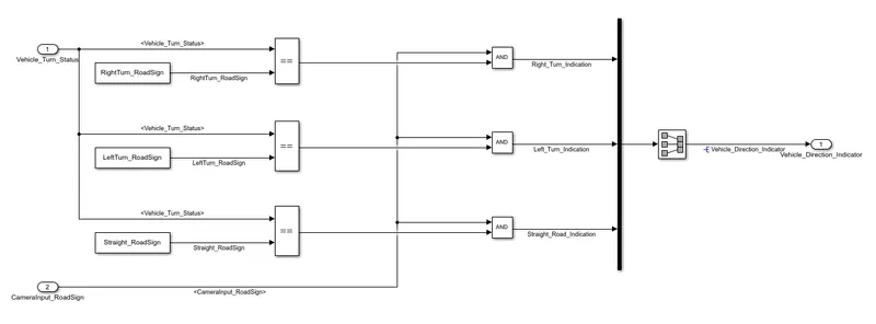
The above figure shows inside the requirement 2 subsystem, in this there are two inputs one is vehicle turn status which is determined by the requirement 1 and another is camera input road sign. Vehicle turn status compares with Right turn road sign, Left turn road sign and straight road sign and output signal of relational operators and camera input road sign signal is the same then these signals sent to the vehicle direction indicator as vehicle direction. In this model relational and logical operators are used.
Requirement Tagging:
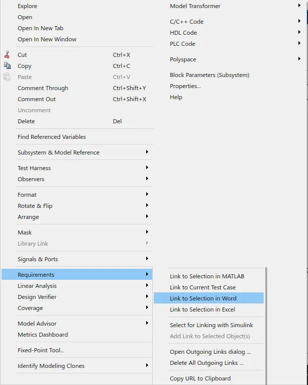
For requirement tagging we want to write all requirements in one word or excel file. After that select the portion which we want to tag the subsystem and go to the model right click on that subsystem go to the requirement and select link to selection in word now our subsystem tag to the word file.
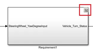
Now one sign will be displayed on the subsystem for redirecting to the requirement file.
Model Configuration Parameters:
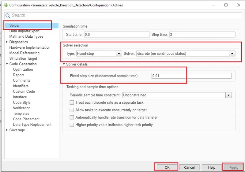
When we build a model for model based development at that time we want to take care of some model configuration settings. For changing the model configuration parameters go to the Modelling tab click on the model setting then new configuration window will open in that go to the solver section and select solver type is Fixed-step, solver is discrete (no continuous states) and Fixed step size (Fundamental sample time) is as per your requirement in our case is 0.01 sec. then select apply and ok.
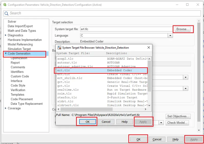
In our requirement they mention to generate code for the model, so for code generation we want to change some default settings. For that go to the code generation section change the system target file grt.tlc to ert.tlc (Embedded coder). For changing this setting click on browser and select ert.tlc and then click on apply and ok.
Data Dictionary:
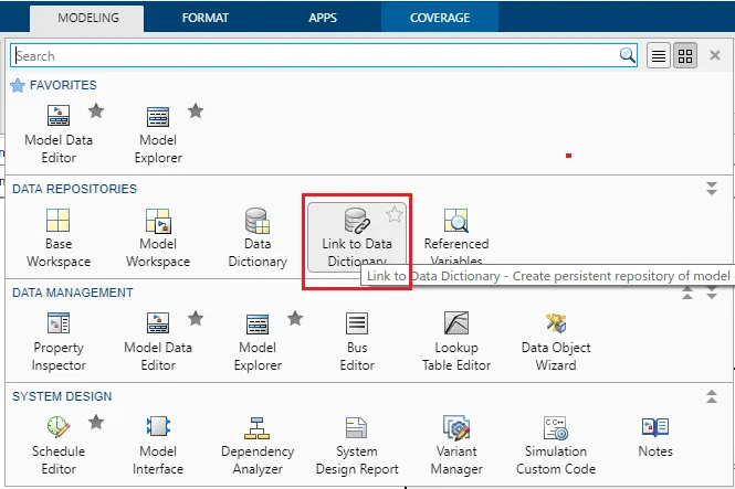
For creating the data dictionary goto the modelling section select link to the data dictionary then a new window opens in that type the data dictionary and disable the ‘Enable model access to the base workspace’ box then click on the new and apply ok. Now save in the same model file folder, so in the model bottom left corner one data dictionary symbol displays by using this we can go to the model data dictionary.
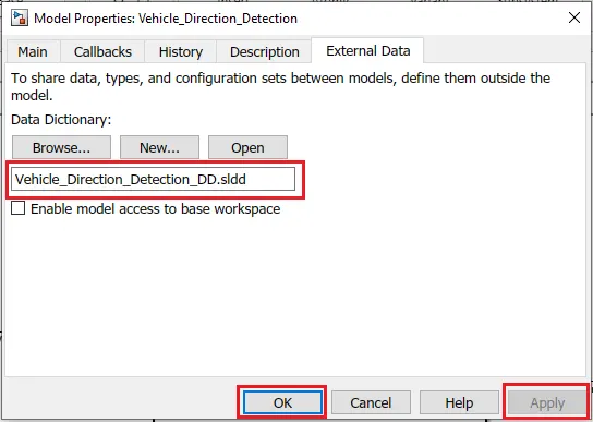
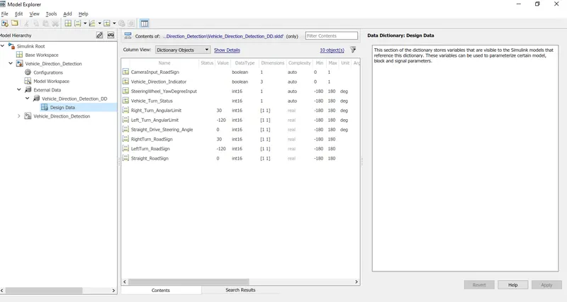
After opening the data dictionary, assign the parameters and signal of the model. After assigning the model data dictionary look like as per below figure.
Model Advisor Test:
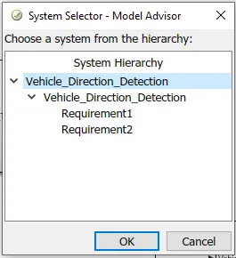
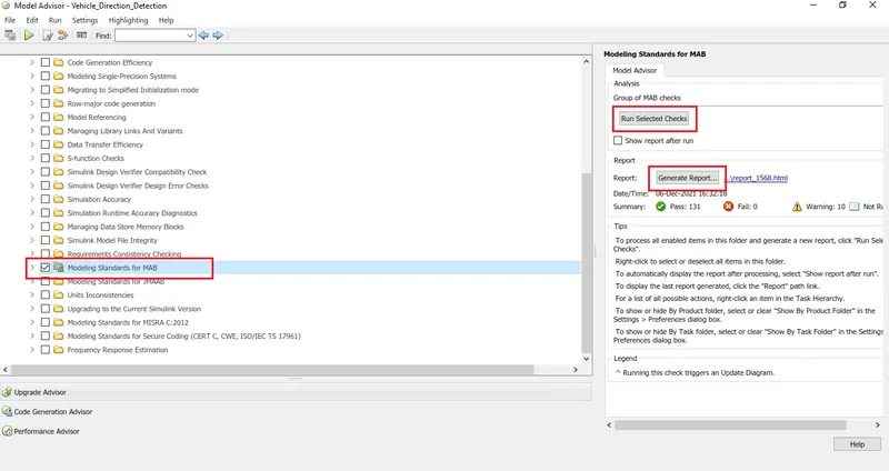
For model advisor test click on modeling select model advisor then select our model, now new model advisor window will open select the Modelling Standard for MAB and click on the run selected check then automatically testing will start after completing minimize the warning by changing recommended change and generate report.
Code Generation:
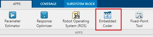
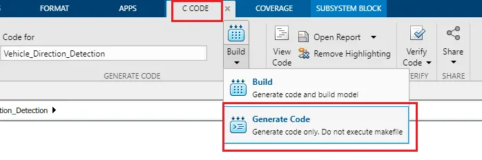
For code generation we already change the model configuration parameters, so now go to the Apps section select Embedded coder then new section open C Code in that click on build and select the Generate Code. Now automatically code will be generated and displayed on the right hand side of the model.
Also model right hand bottom corner one sign display by click on that we can direct go to the generated code and our requirement file.