Project 1
Aim :- Design a battery pack for the car with 150Kw capacity.
Objective :- Design the battery pack configuration.
Draw the BMS topology for this battery pack.
Theory :-
Battery Management System,
A Battery Management System AKA BMS monitors and regulates internal operational parameters, i.e. temperature, voltage and current during charging and discharging of the battery. In technical terms, the BMS estimates the SoC (state of charge) and SoH (State of Health) of the battery to improve safety and performance.
It avoids over-charging and over-discharging of the battery pack. This way, it maintains charge level within maximum and minimum allowed capacity to prevent sudden accidents [explosion]. Hence a BMS is a highly crucial device to ensure the safety of the battery and user. There are many other benefits of using BMS; we will discuss them later in this article.
A BMS is an electronic board consisting of a variety of components and circuitry. After detecting a problem in operational parameters (voltage, temperature etc.) BMS triggers input to the alarm system followed by disconnecting the battery pack from the load or charger.
Different BMS Topology:
The components of a battery management system can be arranged in several different ways. These arrangements, called topologies, can be centralized, distributed, and modular.
Centralized BMS Topology:
In a centralized topology, there is a single BMS printed circuit board (PCB) with a control unit that manages all cells in a battery through multiple communication channels. This type of arrangement makes a BMS a bulky, inflexible yet cost-effective solutions.
Distributed BMS Topology:
Here, every battery cell has its own BMS PCB, and a control unit is connected to the entire battery through a single channel. The daisy chain is one of the distributed topology variations intended for systems that have a small need for fault tolerance. Distributed BMSs are easy to deploy but costly because of the abundance of electronics.
Modular BMS Topology:
A modular BMS is a combination of the above two topologies. This arrangement is also known as decentralized, star, or the master and slaves topology. There are several interconnected control units (slaves), and each of them oversees a group of cells in a battery. The slaves are connected to the main control unit or master, which handles the integrity and safety of the whole battery. A modular BMS topology can provide a balance between the price and design complexity.
1). Ans:
Battery Pack Configuration
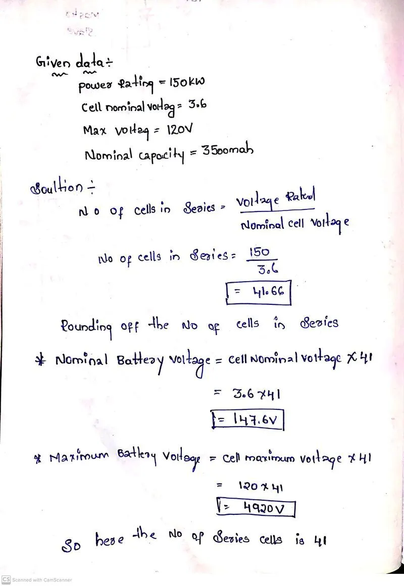
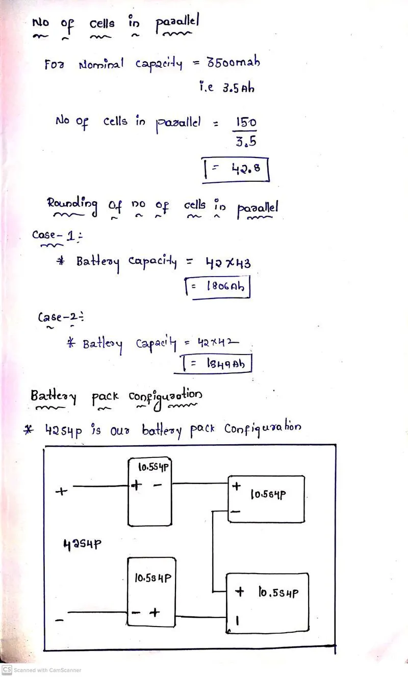
So here we Designed the battery pack configuration by calculating the no of cells in series and no cells in parallel and we also done the rounding off the no of cells in series and parallel
2). Ans:
BMS topology for this battery pack,
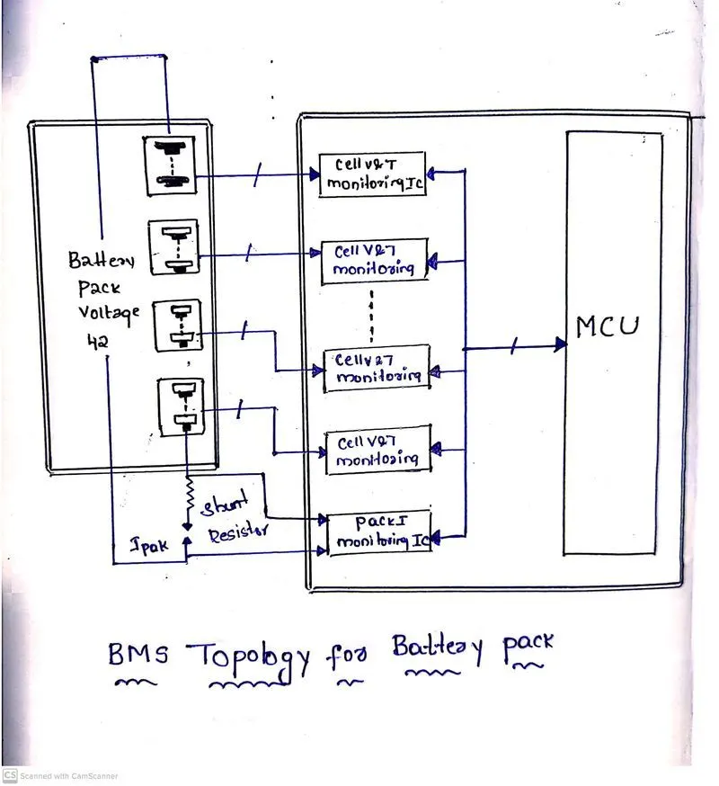
- Here we mainly used the Master Salve topology because This architecture comprises of the Master and Slave BMS units.
- so by this The slave unit monitors balances and controls a group of battery cells within the battery module.
- It communicates with the master unit through a communication interface.
- The Master unit is responsible for state estimation control of Power Distribution Unit PDU and external communication.
- The master-slave BMS is similar to a modular system in the sense that it uses multiple identical modules the slaves each measuring the voltage of a few cells.
- However the master is different from the modules and does not measure voltages.
- It only handles computation and communications.
- Importance of BMS Architecture for EV Battery Systems
- Measurement Precision
- Connection Reliability
- Expansion Versatility