Project 1
WIRING HARNESS DESIGN PROJECT 1
AIM
Design and develop the Wiring harness on Given V6 Engine and Prepare flatten view drawing in CATIA V5. Application of all Packaging rules, Industry best practices studied in this course shall be demonstrated in design.
INTRODUCTION
A wire harness, also commonly referred to as a wiring harness, is an exterior sheath used to cover some types of electronic wires. Generally, wiring harnesses are made of thermoplastic or thermoset materials that can help protect the cables from the environment.
Engine Harness
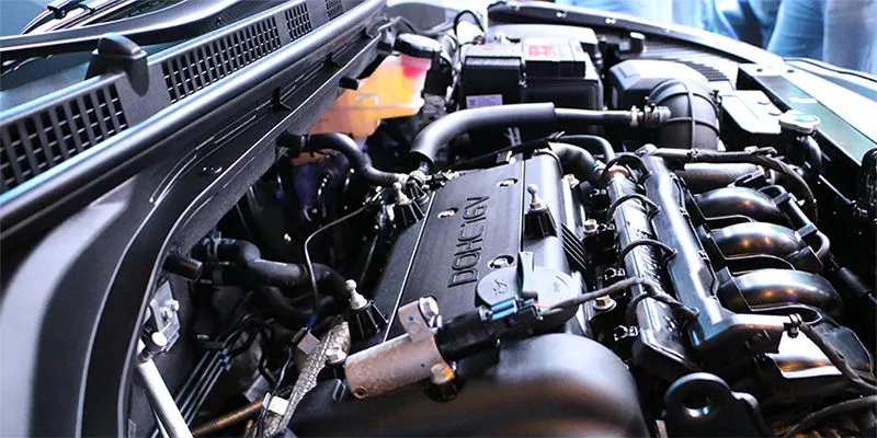
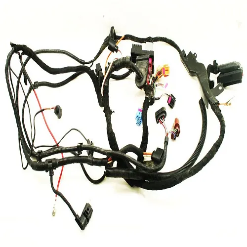
An engine wiring harness is constricted wires, cables, terminals, and connectors controlling a vehicle’s electrical system. It relays electrical power and control information to components such as batteries, alternators, fuel injectors, fuses, audio systems, blower motors, fuel injectors, and computers. Wire harness companies customize it for every location, application, and design it interconnects. Also known as a cable harness, it is more than just a collection of multiple wires put together.
It manages the key functions around the engine including engine controller, oil controller gate, transmission plug housing, air pipe sensors, pressure sensors, and water temperature sensors.
An engine wiring harness is how each part of your vehicle gets electricity. It is crucial to help the vehicle run and it’s usually made of a heat-resistant rubber to handle the high and low temperatures that vehicles often experience. The vehicle needs more than the engine, and it requires a lot of electricity for certain things to function, like the radio or lights. Beyond that, battery, starter, and even alternator run on power, which is provided by the engine. Without an engine wiring harness, we couldn’t start your vehicle.
How Does the Engine Wiring Harness Work?
There are many cables in the engine wiring harness that work to connect electricity to your vehicle parts. This vehicle part has many sensors, and they work to ensure that everything in your vehicle is in working order. Some of these major systems in your car are fuel and transmission. When you get a check engine light, you have the engine wiring harness to thank.
It works by using these cables and a fuse box. They wire the electricity produced by the engine to the various parts and sensors. It is created using high-temperature plastic or rubber because the engine heats up a lot. That could cause the engine wiring harness to melt over time. And while this is a rare occurrence, it does happen.
Think of this part of the vehicle like the brain. Without it, it wouldn’t be possible to get the information your vehicle needs. It’s always working overtime to relay the data your vehicle needs to function correctly. Whenever a sensor goes off, it’s because the engine wiring harness alerted the sensor of the problem.
The exciting thing is that as vehicles get more advanced, the engine wiring harness grows. Some say that new cars have over 100 pounds of wires, so imagine how many things could go wrong with that. In the past, there may not have been many issues. However, as things advance, there are more to go wrong.
Engine Wiring Harness protection
Protecting the wires is crucial to the safety of the vehicle. Wires exposed to high temperatures, erosive chemicals and projectiles will be damaged leading to fires, brake failures and critical malfunctions. To prevent these issues, wires need to be bundled and covered.
install wiring insulation or heat shield sleeve material that can withstand direct contact with high-temperature surfaces and is flameproof. It needs to be a material built specifically for under hood automotive applications and withstand constant temperatures up to 125°C, or 257°F.
There are many options for protecting the wires in a vehicle’s harness. Zip ties securely bundle wire together but offer little protection or insulation. Plastic conduits offer protection from rough surfaces, although they can add weight and are not as flexible as other options. Heat-shrink tubing provides protection from heat, moisture and chemicals. However, the application is time-consuming.
Tape is another option for bundling and protecting wires. Tapes are more flexible and cost-effective than other bundling options because they can be used for protective wrapping, bundling and sealing. With a wide variety of backings and adhesives, tape can offer sound dampening, thermal and electrical insulation and abrasion protection of the same quality of the other methods. Additionally, tapes are more flexible, lighter and easier to apply than tubing or plastic conduit.
Objective- The objective of the project is to route the wiring harness on given Engine and prepare flatten view drawing in CATIA V5. All types of packaging rules have to be considered while routing the harness. Also, Industry best practices should be demonstrated in design. All the necessary details like clearance, clipping/clamping selection, harness fixing requirements, harness continuity should be provided in order to design wiring harness.
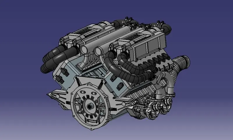
Fig. Bugatti V16 Engine
- The above figure shows the 16 valve Bugatti Engine where 8 cylinders are placed on the right side and 8 cylinders are placed on the left side.
- There are total 16 injectors where 8 injectors are used for 8 cylinders on right side and 8 injectors are used for another 8 cylinders on left side.
- Also there are 4 cam-shaft sensors, so there are total 20 sensors that we have to connected electrically.
- Generally, 4-pole connectors are used for fuel injectors of the engine.
- The engine will also have an interconnection connector which will connect the engine to other parts of the vehicle. We will be using a 12-pole electrical connector with a mounting clip feature as an interconnection connector.
- The plastic guiding channel used in this harness should bemade of a material that can withstand at least 150 degree Celcius.
- The bend ratio for the all bundle segmets should be 1.4
DESIGN METHODOLOGY
Step 1: Download the engine CAD data and required connectors CAD data from the given source.
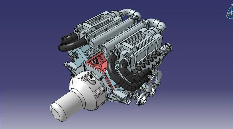
Step 2: Download the required Connectors from the source and convert the mechanical connectors electrically by using the electrical part design work bench by following below steps.
- First download the connectors and mounting clip from the given link source.
- Get into the mechanical part workbench to create required geometrical parameters. Create connector connection point and bundle connection point on the required sides of the CAD part.
- Create axis system on the connector connection point such a way that the Y coordinate facing normal to the connector face, X coordinate facing towards the locking mechanism and Z coordinate facing to the top.
- Create cavity connection point for connectors having the cavity for mounting clips
Using the geometrical parameters created,
- Define part as electrical connector.
- Define bundle connection point.
- Define connector connection point.
- Define cavity connection point.
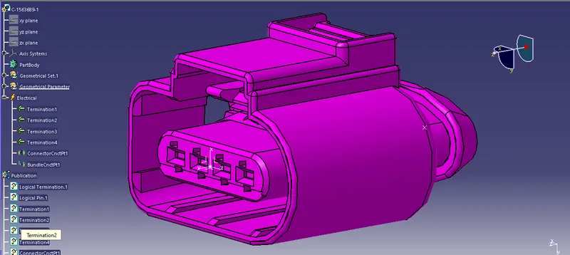
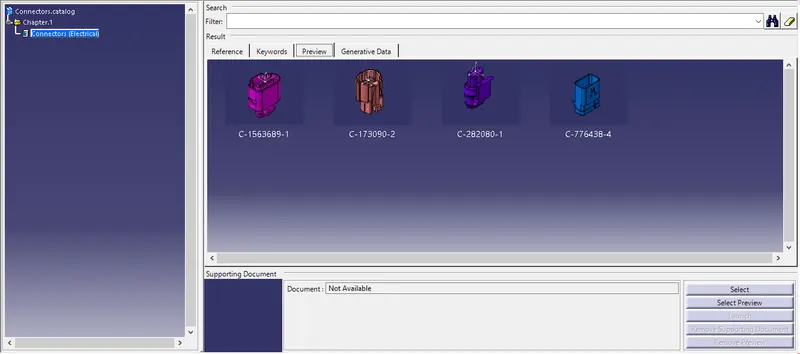
4 pole connector
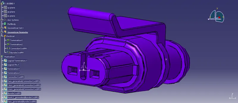
2-pole connector (C-282080-1)
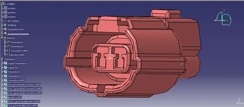
2-pole connector (C-173090-2)
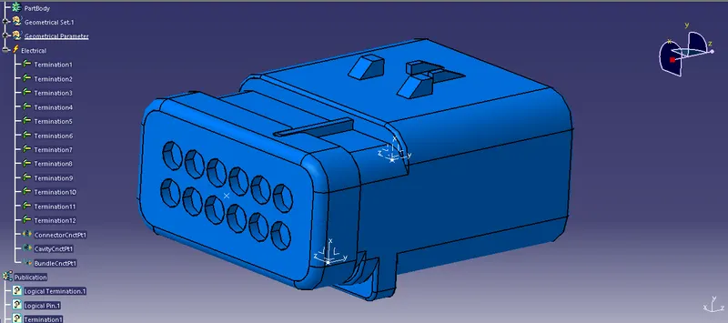
Inter Connection Connector (C-776438-4)
Adding Connectors to the Catalogue
STEP 3: Creating the context assembly
Context assembly is nothing but the product file which contains the engine 3D-CAD data and the engine harness geometrical bundle. Here the geometrical bundle product contains all the connectors and other mounting equipments, clips and clamps which are electrically defined for the assembly. Sheet metal L-clamp are added in the main context assembly.
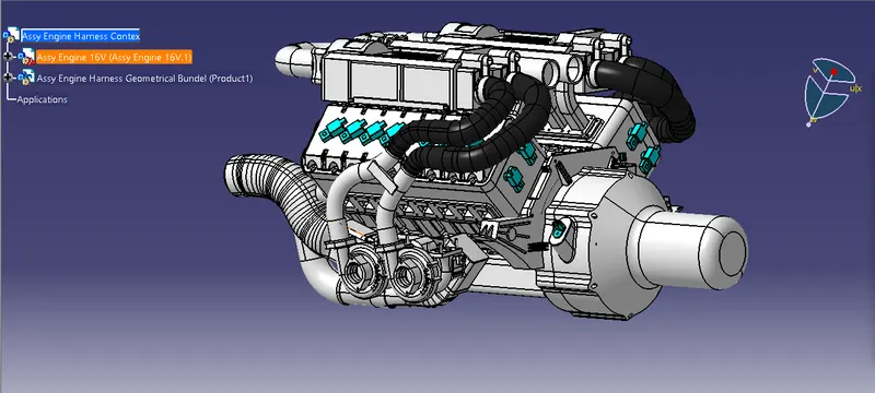
The we need to switch into the electrical harness assembly workbench and Geometrical bundle product file should be electrically defined using the Define Geometrical bundle option before adding any parts into it.
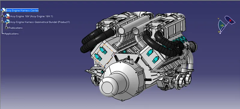
The Given V16 engine 3D-CAD model requires a total of 23 connectors to be placed on it and an inter connection connector for the engine wiring harness assy. The connectors used in this engine are as follows
- 8 numbers of connectors are required on the fuel injector sensors on each cylinder head, i.e.; total 16 fuel injector sensor connectors are needed.
- Total 4 numbers of cam-shaft sensor connectors are needed.
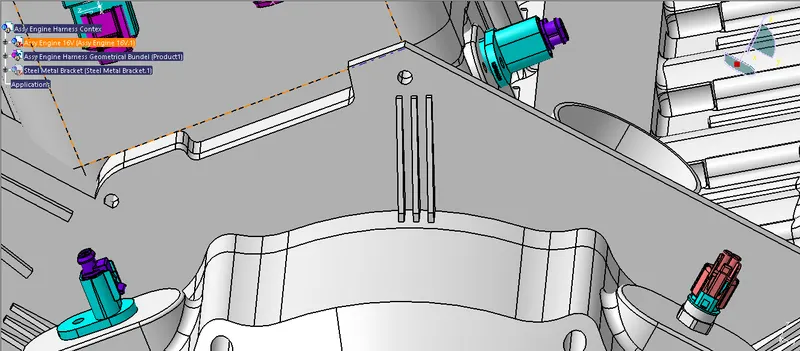
- 1 neutral position sensor connector and 1 speed sensor connector on the gear box housing.
- 1 engine coolant temperature sensor placed at the center of engine.
STEP 4: Adding connectors to the all 16 fuel injector sensors and 4 cam-shaft sensors
In this step, we are placing connectors to fuel injector sensors and cam-shaft sensors. So we will require total 20 connectors which have to be added in the Engine Harness Geometrical Bundle Assembly. We have to use manipulation tools along with compass, snap and smart move features to locate all the 20 connectors at their desired locations.
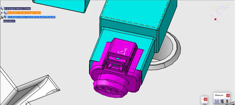
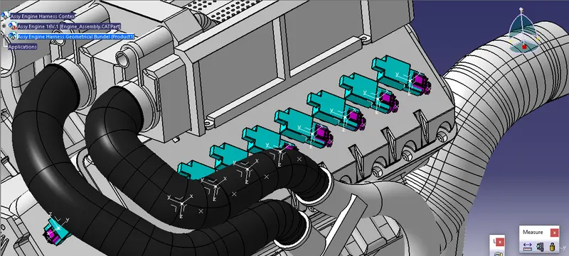
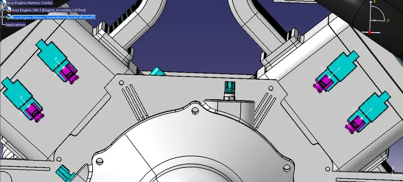
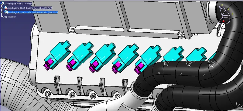
STEP 5: Adding all the other connectors for sensors like coolant heat sensor, neutral position sensor, speed sensors.
STEP 6: Adding sheet metal bracket
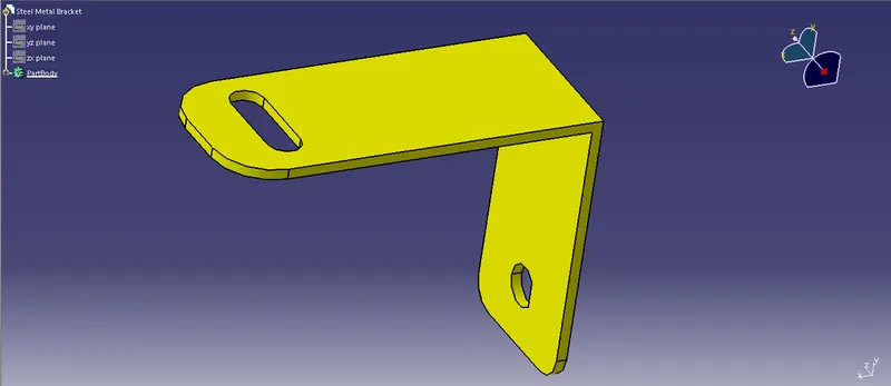
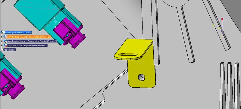
Now, we have to add sheet metal bracket in order to provide mounting for the interconnection connector. Also, we have to make sure that the bracket is placed inside the context assembly and outside of engine and geometrical bundle assembly. The bracket should be mounted on the existing bolt as shown below. This bracket should have locking system in clockwise direction so that it can't be move freely. Herein below figure, rib is performing the locking feature for the bracket. All the design ideas should be discussed with the engine designing team so that there won't be any disturbance for the smooth working of engine in real world application.
Step 7: Mounting the interconnection connector on the sheet metal bracket and mounting the p-clamps for wire harness
Here, a 12 pole connector "C-776438-4" and mounting cavity "C-1924487-2" is together used as interconnection connector. The required cad data is downloaded from te.com. First, we have to define 12 pole connector and mounting cavity electrically as below.
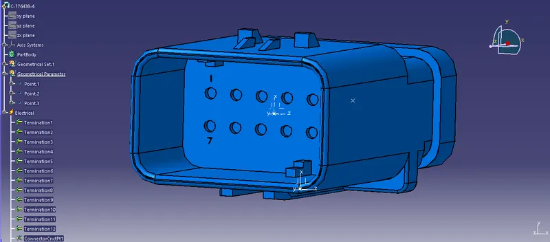
- A 12 pole connector "C-776438-4" is electrically defined as shown in above figure.
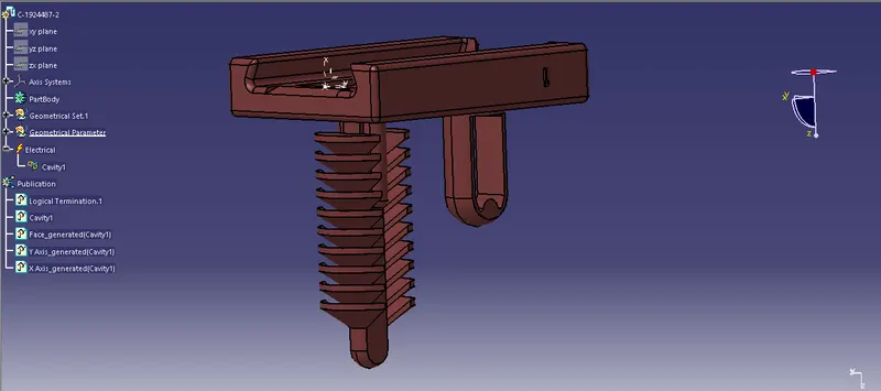
- A mounting cavity "C-1924487-2" is electrically defined as shown in above figure.
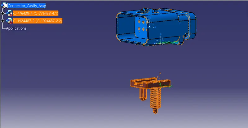
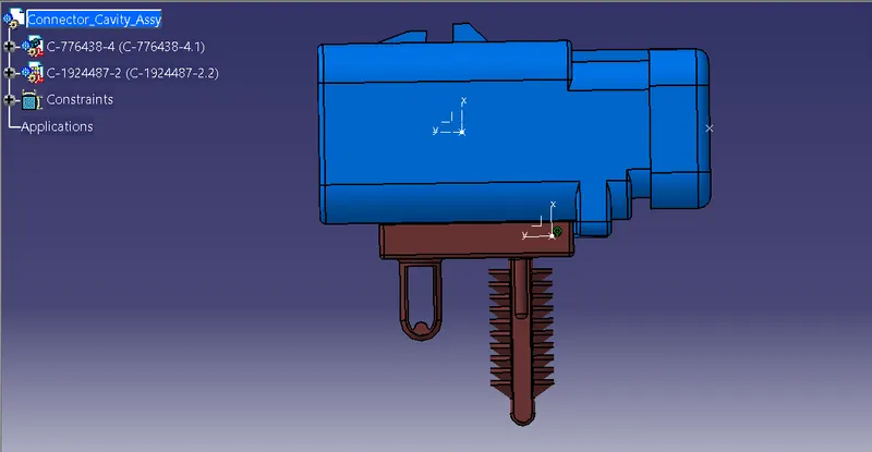
- Above figure shows that, both 12 pole connector and mounting cavity are electrically connected together in electrical assembly design workbench.
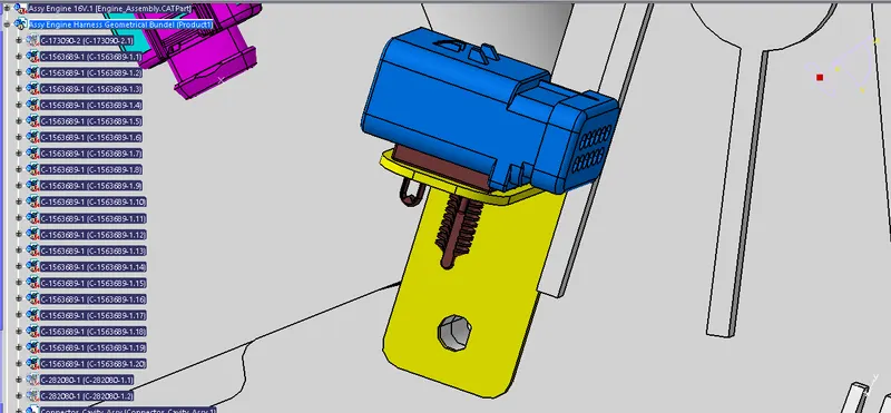
- Now, we have to mount that electrically connected interconnection connector and cavity on sheet metal bracket as shown in above figure.
- We have to mount 3 P-clamps also on the existing bolts of the engine so before that we have to define P-clamp electrically with geometrical parameters, entry and exit point on both left and right side of the P-clamp as shown in below figure.
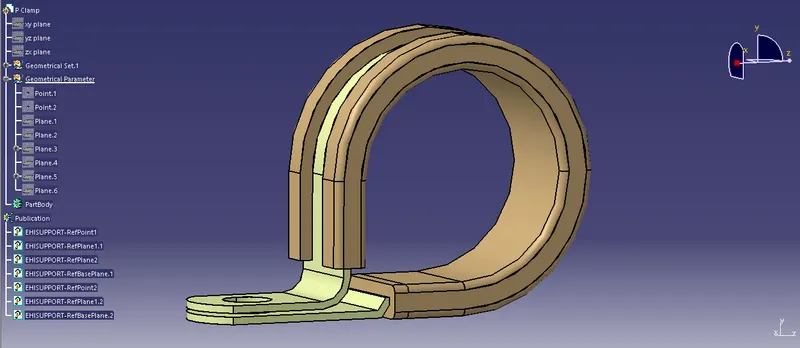
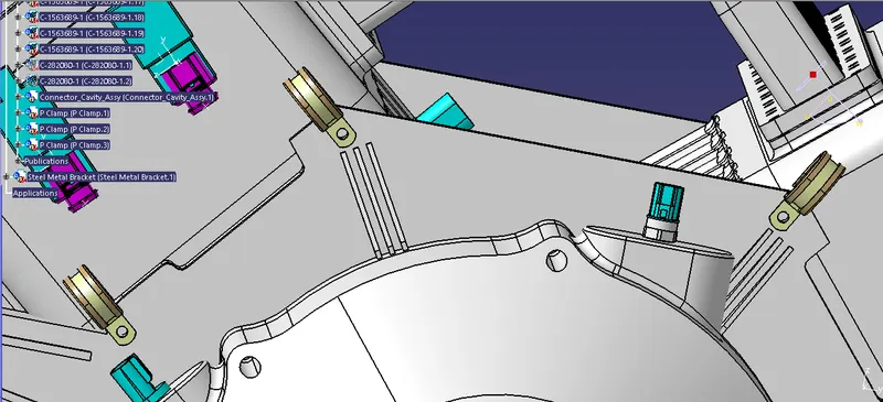
- Here, we have mounted 3 P-clamps on the existing bolts of the engine for the wire harness routing as shown in above figure.
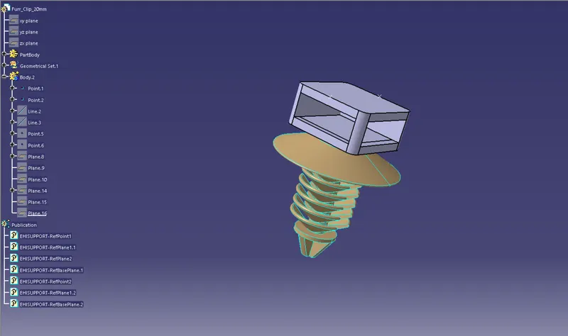
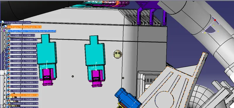
- In above figure, we have mounted furr tree clip also for the smooth path to wiring harness routing towards guiding channel on both right and left side.
Step 8: Mounting of a plastic guiding channel
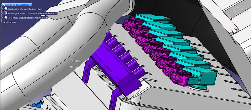
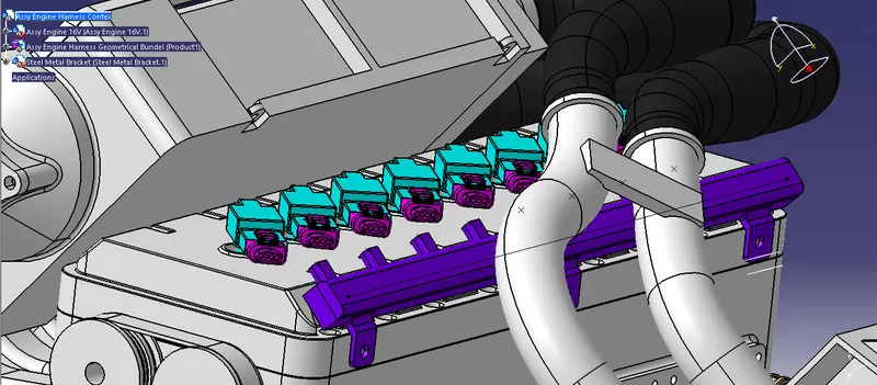
We have to add now plastic guiding channel because Bugatti V16 engine has 8 injectors on right side and 8 injectors on left side which are very close to each other. Hence plastic guiding channel is best option for proper and easy routing of the wiring harness. It will reduce the complex wiring harness routing. We will require two different guiding channel for both right and left side of the engine. Now, before placing guiding channel, we have to define geometrical parameters of guiding channel as below.
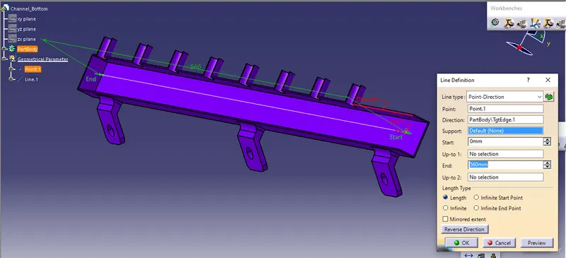
- In above figure, we have created point 1 at entry face and another point at endpoint at 560mm distance.
- Now, join that both points and create a line which will be later used for routing the wire harness bundle inside the guiding channel.
- Above figure shows for the left side guiding channel and same process will be repeated for the right side channel.
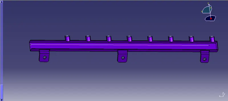
- Now in above figure, we have created bundle entry points for the eight connectors, one bundle entry point at channel entry face and defined guiding channel electrically as equipment.
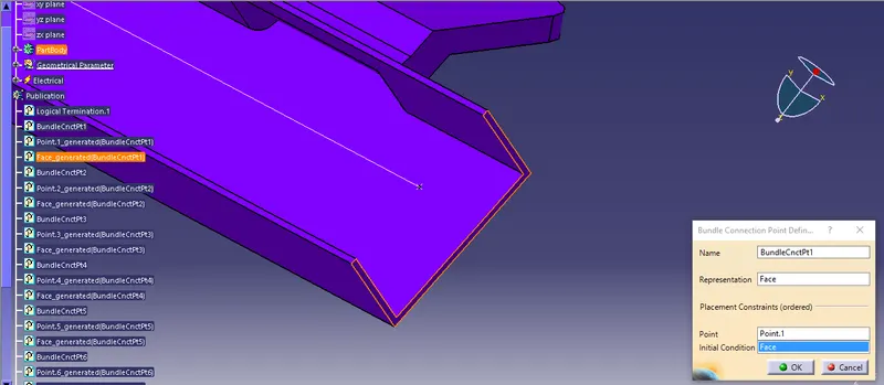
- In above figure, we have shown bundle entry point at face of guiding channel.
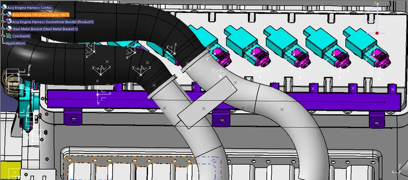
- After electrically define of guiding channel, we have located guiding channel at desired place as shown in above figure.
- Here, we have used different commands like manipulation, snap, smart move, compass etc. for placing of guiding channel.
- Now at this stage, we have just located bottom of the guiding channel.
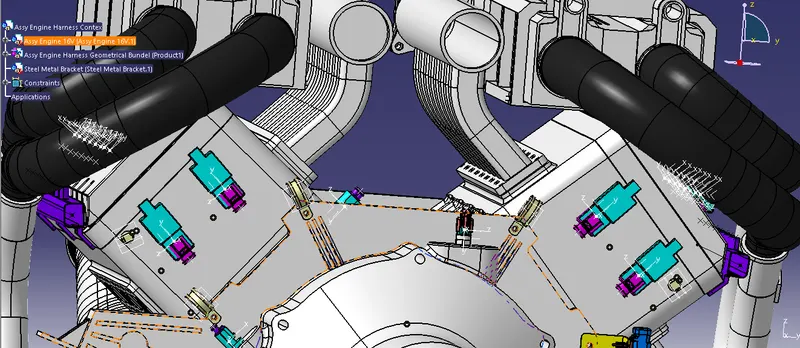
- In above figure, whole assembly is ready for the routing.
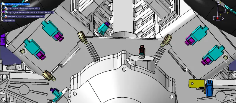
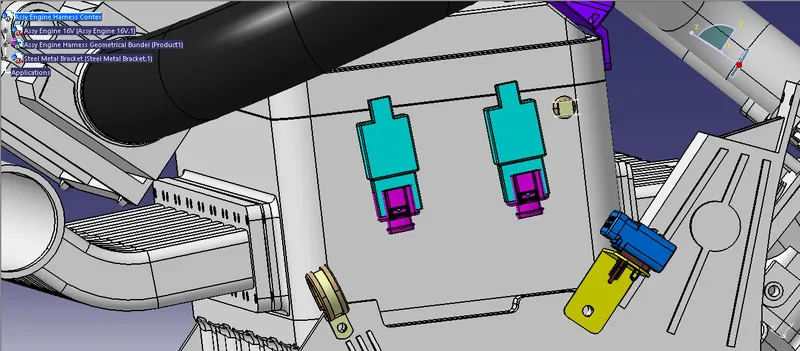
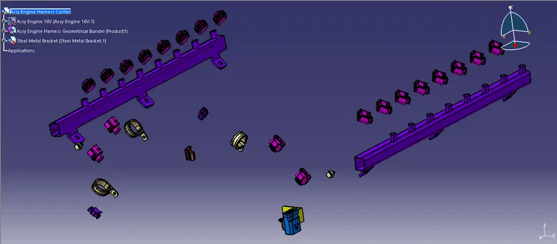
- All 20 connectors, 3 P-clamps, 1 Interconnection connector, 2 furr tree clips and 2 plastic guiding channels are mounted.
Some important packaging rules and best practices to be considered during wire harness routing and placing of the clips and clamps are as follows –
- Distance between two clamps on a straight branch should be minimum of 200mm.
- The minimum branch length should be 50mm.
- Minimum distance between clip and nearest branching point should be 25mm.
- The minimum distance between two straight connection points should be 200mm.
- The minimum distance between two breakout points should be 50mm.
- To limit the number of branches from a single branch point to 4.
- Avoid routing wiring harness near the exhaust manifold and its components and also from other unshielded heat sources. If re routing is not possible then maintain a minimum distance of 200mm.
- Try to avoid use of too many metal brackets on engine. Try to use the available threaded bosses on engine or demand for it.
- Enough clamps shall be provided to ensure positive clearance with surroundings and safety of wiring harness.
- P - Clamps, Fir tree clips and other clips can be added to the Geometric bundle as they are electrically defined and are part of the Wire harness routing and should be provided with the Wire bundle package.
- Enough slack should be provided to the wiring harness which help not to get damaged during the Engine rocking or starting condition.
- The wire harness routing should be done in such a way that it is easy in manufacturing and serviceability.
- The wire routing should be done keeping in mind the cost effectiveness of the bundle package.
- To avoid the harness routing and clipping in blind zones of the operator during the assembly and the service.
- To provide proper slack at end connectors so that there will be no tension on the wire bundle.
- To avoid sharp edges on the sheet metal parts and if it is not possible then provide protection parts to prevent damage of the wire bundle.
- To provide separate branch points for separate connectors to ensure Poka-Yoke.
Keeping all the above packaging rules we can start the routing of the wire and provide clipping and clamping wherever necessary during the routing process.
ENGINE with all the components for wiring harness routing
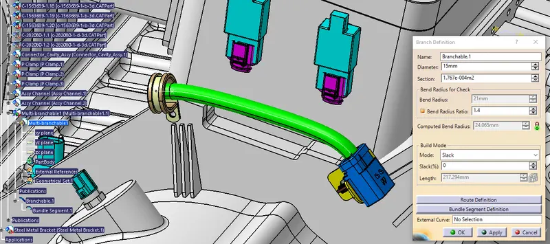
Step 9: Bundle routing from Interconnection connector to 3 P-clamps
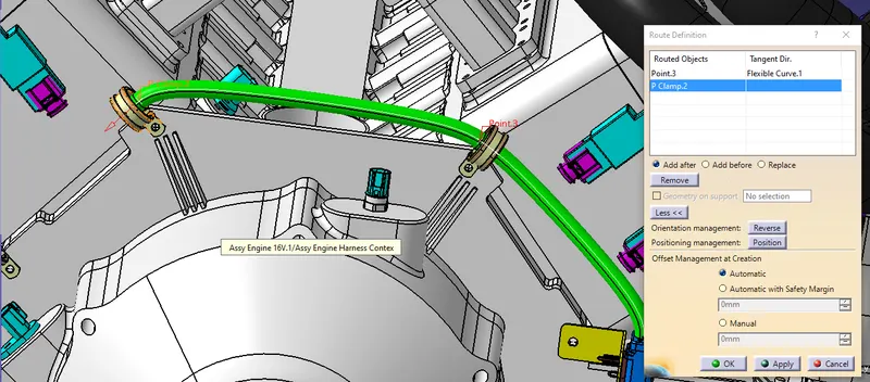
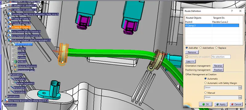
Here, we are routing the bundle segment from interconnection connector to 3 P-clamps. The diameter for this routing path is 15mm and bend radius ratio is assumed to be 1.4
Step 10: Adding branch points to 4 cam-shaft sensors.
Adding branch point to the bundle segment at a required distance as shown in below figure.
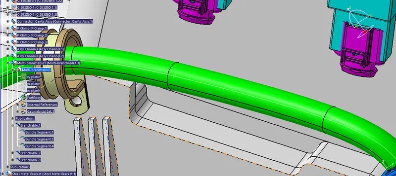
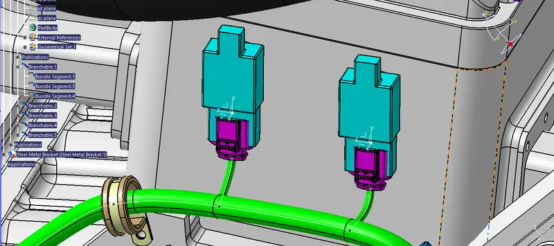
- In above figure, two branches are added from the created branch point to cam-shaft sensors.
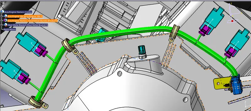
- In above figure shown that the routing for 4 cam-shaft sensors is completed.
Step 11: Adding branch points to 4 cam-shaft sensors.
Adding branch point to the bundle segment at a required distance as shown in below figure.
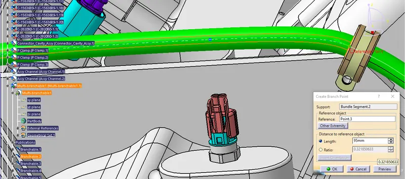
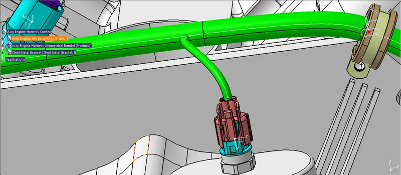
- In above figure, two branches are added from the created branch point to cam-shaft sensors.
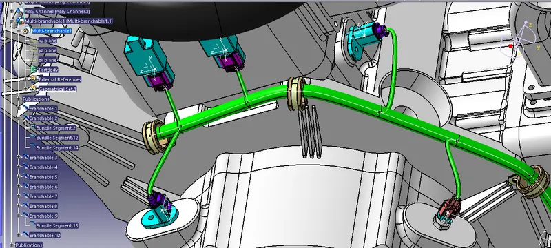
- In above figure shown that the routing for 4 cam-shaft sensors is completed.
Step 12: Routing to the plastic guiding channel
Another branch point is added from the interconnection connector at distance of 50mm. From this branch point, the bundle is routed to the right guiding channel. We have provided furr tree clip in between branch point and guiding channel for the smooth routing.
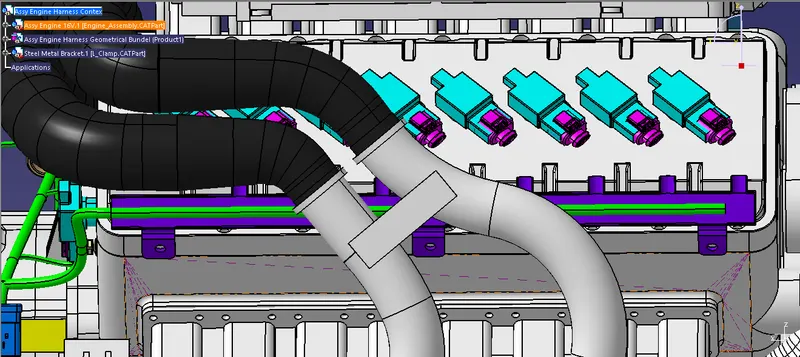
- In above figure, we can see that the bundle segment inside the guiding channel is created by using pre-made sketch as routing definition. The bundle diameter is assumed to be 8mm.
Step 13: Adding branch points to bundle segment inside the guiding channel
Here, from the entry side of the guiding channel, we have created first branch point at 130mm and then subsequently created six branch points at 65mm as shown in below figure.
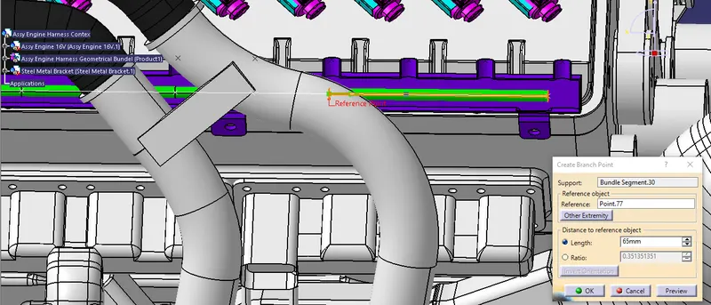
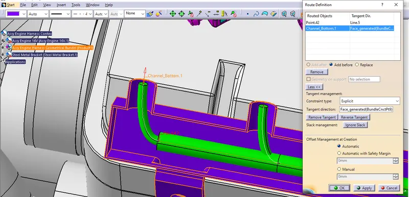
- In above figure, we are routed bundle segment from the newly created branch points to the 8 fuel-injector connectors. The bundle diameter is assumed to be 5mm.
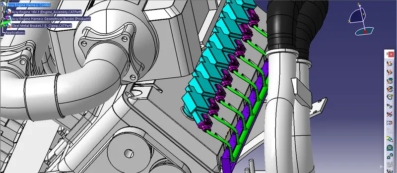
- In above figure, we have done routing for all the 8 fuel-injector connectors.
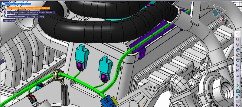
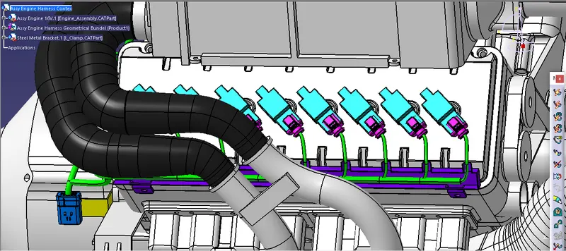
- Similarly, we have done routing for the left side guiding channel also as shown in above figure.
Step 14: Checking bundle continuity
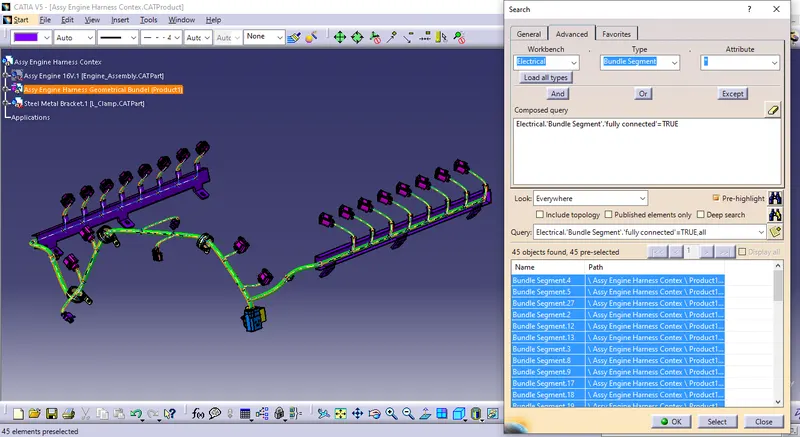
In this step, first we have to make sure that multi-branchable is selected then we have to go in Edit>Search>Advanced>Workbench-Electrical>Type-Bundle Segment>Attribute-Fully Connected
- By selecting 'True' option will show all the connected bundle segments while selecting 'False' option will show all the non-connected bundle segments.
- Here, we have selected for the 'True' option and searched for results. All the bundle segments are highlighted found showing that all the bundle segments are electrically connected as shown in below figure.
Step 15: Adding protective coverings and guiding channels top shell to harness bundle
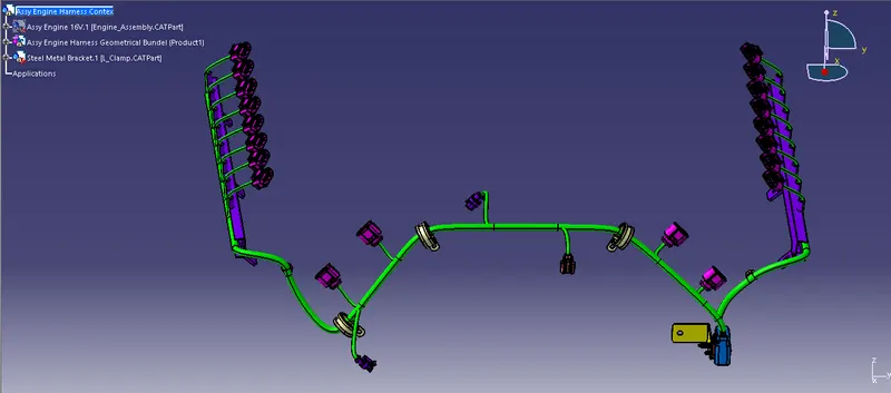
Here in below figure, we have done with whole wiring harness routing for the Bugatti V16 Engine. Now, we have to add protective coverings to all bundle segments and top shell of the guiding channel.
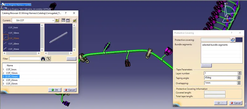
- In above figure, we have added 15mm slit COT tubes on top of the bundle segments as a protective covering. We have assumed start and end extremity for the COT tubes approximately.
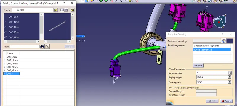
- In above figure, we have added 7mm slit COT tubes on top of the bundle segments as a protective covering. We have assumed start and end extremity for the COT tubes approximately.
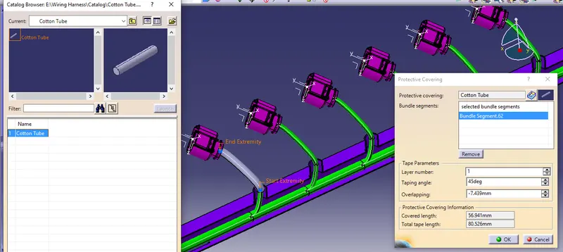
- In above figure, we have added 7mm Cotton tape on all the bundle segments connecting to the all 20 connectors.
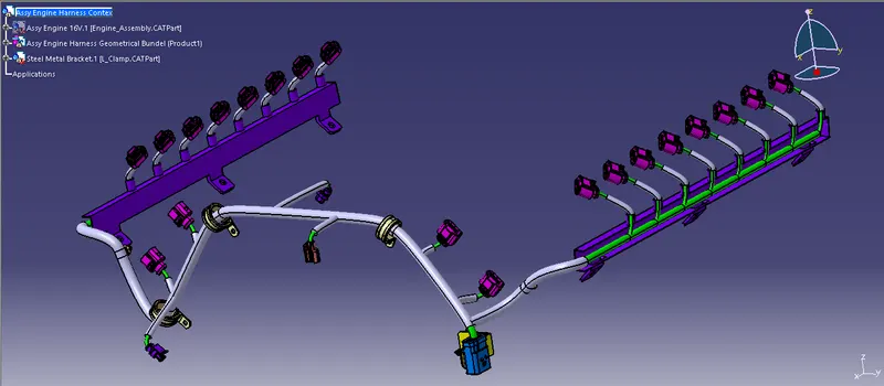
- In above figure, we have added all the slit COT tubes and cotton tapes on bundle segments as a protective coverings. Also, we have added top of the both left and right side plastic guiding channel.
Step 16: Creating flatten view of the engine harness geometrical bundle assembly
In this step, for creating flatten view we have to work in Electrical Harness Flattening workbench of Catia V5. We should also make sure that the flattening file is saved in the same folder where other files of harness assembly are saved.
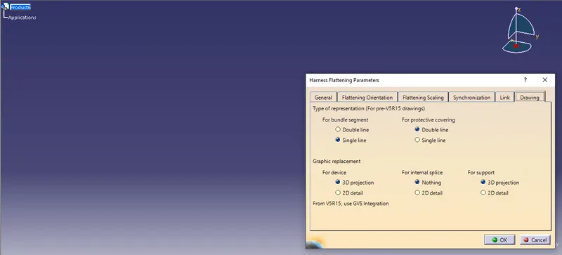
- Before creating flatten view, first we have to define flattening parameters. Make sure that selecting 'Single line' for bundle segment and 'Double' line for protective covering.
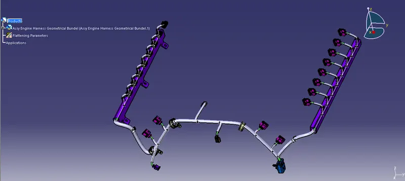
- We have extracted the bundle assembly into Engine Harness Flattening Product file and then flattened the file along face of interconnection connector as shown in above figure.
- At this stage, for clarity, we have been hidden the flattening diagram of the plastic guiding channels from the drawing view.
Due to some Software issue the cot tube, cotton tube and mounting cavity is not loading in Flattining. When I open it for first time it is showing but when i save it and open it for the second time it is not showing you can see it in the abowe image.
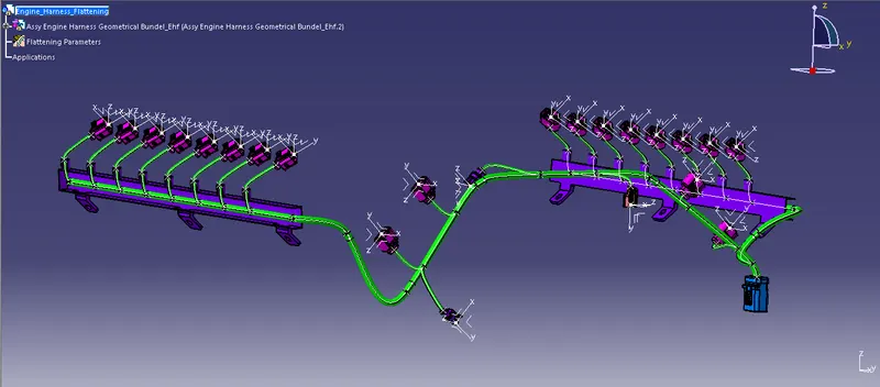
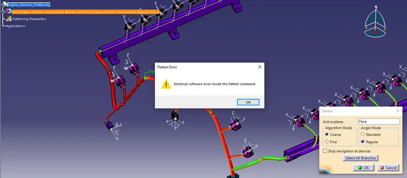
And also whenever i am trying to use the flatten commend it is showing the error.
Step 17: Creating a flatten view drawing for the wiring harness assembly
I am not able to flatten the geometrical bundle so the drawing is not possible.
Conclusion:
In this project i have successfully routed the wiring harness for the V16 Engine assembly was prepared in CATIA V5. Various packaging rules and constraints were considered while routing the harness. After finalizing the wire routing, we can request the corresponding Engine design team to provide additional holes for the mounting of Fir tree clips.