Week 9 - Project 1 - Door Trim Lower with Engineering Features
AIM:-
To make the Core and Cavity Design
In this model we have to consider the following things:-
Tooling axis
Draft analysis
Class-A surface
Class- B surface
Class-C surface
Heat stake
Locators
Making a solid model from the surface.
TOOLING AXIS:-
Tooling axis is the defined axis to perform the manufacturing process within the injection molding according to its direction.
CREATION OF TOOLING AXIS:-
First of all analyze the given input surface to see which direction is suitable for creating the tooling axis.
In this model to create the tooling axis we have a flat base surface and tapered side wall surfaces.
Extract the base surface from class A surface
Create a point at the center of the extracted surface.
Fix an existing perpendicular side face to the base surface as a reference to create the tooling axis.
Sketch a line using the point direction option with reference to the yz direction.
Final sketched line is called as tooling axis.
DRAFT ANALYSIS:-
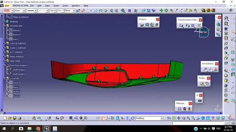
The analyzing of the model should maintain the nominal 3-degree draft angle to the tooling axis.
Draft should be given to the plastic component to reduce the wear and tear and improve the production quality and accuracy while ejecting the part from the mold cavity.
How to perform the draft analysis
1. Go to insert < analysis< feature draft analysis.
2. Align the tooling axis with a compass.
3. Click on the surface to see whether it is in permissible limit draft values or not.
4. The entire surface should be green in colour.
CLASS- A SURFACE:-
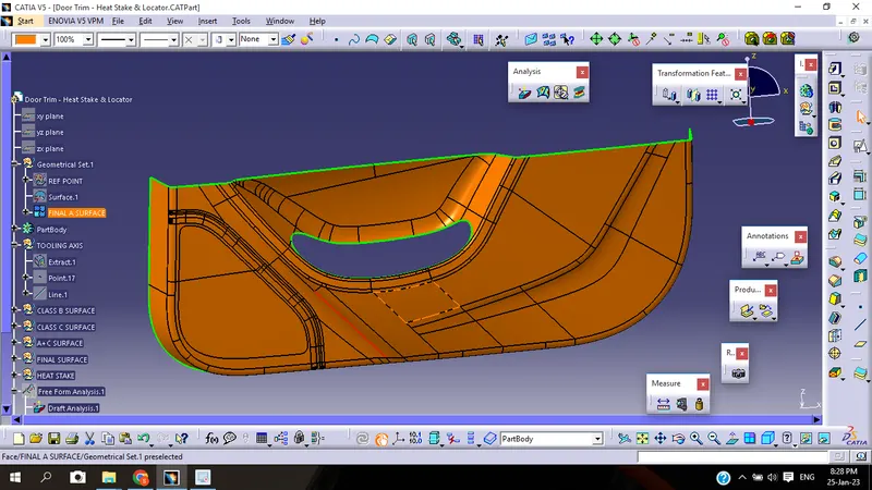
Class-A surface is given as an input surface by designers.
Generally the class-A surfaces have the tangent continuity
Class-A surface is the outermost aesthetic surface.
CLASS-B SURFACE:-
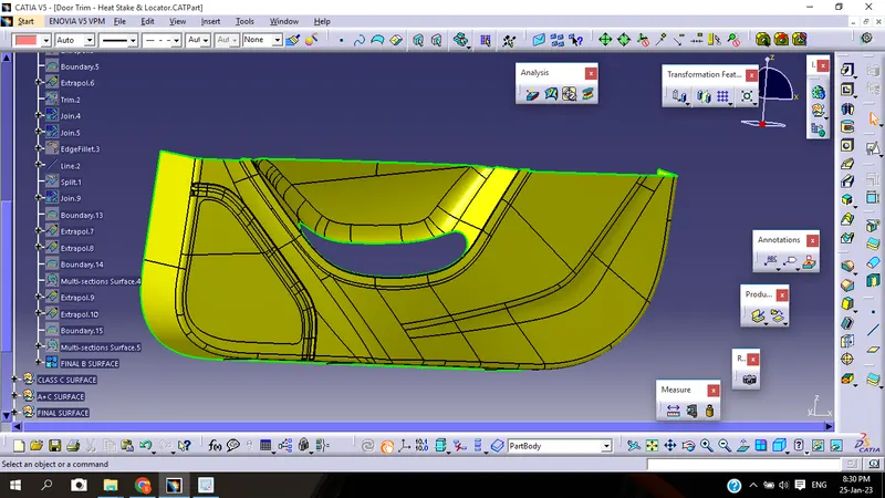
The extraction of the Class-A surface is the class-B surface.
Untrimmed the extracted surfaces from class A.
The untrimmed surfaces are offset to the required thickness.
After offsetting, all the surfaces are trimmed into the required shape.
Give the fillets on the edges, especially given fillet radius values should maintain the uniform wall thickness.
The class B fillet radius value=outer radius value + thickness.
CLASS C SURFACE:-
Class C surface is the closing surface of class A and class B surfaces.
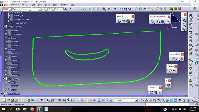
It is the extraction of the boundary of class A surface.
Apply the sweep feature to create the class c surface, For guide reference click the extracted boundary and for the drafting reference option click the tooling axis and give a 3-degree draft angle
HEAT STAKE:-
Heat staking also known as thermoplastic staking is the process of joining two dissimilar materials together.
There are following steps to generate heat stake.
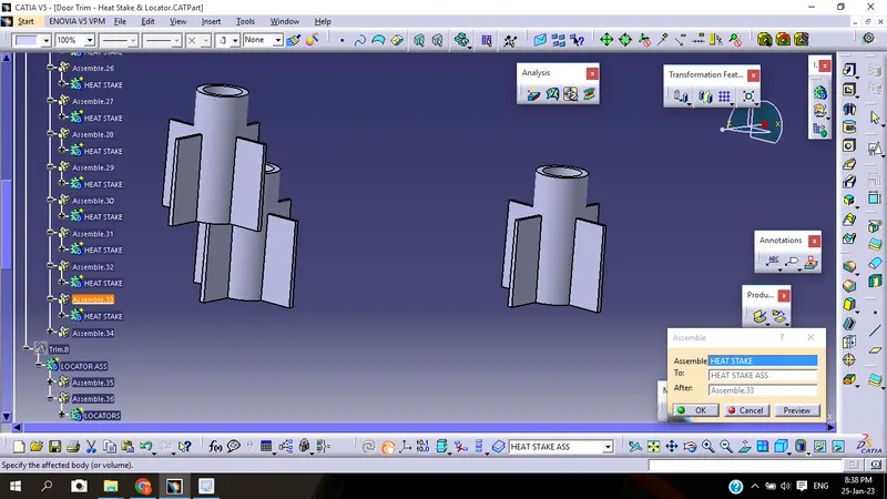
First we have to take the sketch. Then draw the two circle of dia 10mm and 7.5mm. Take the a new 1body and pad the circle of length 20mm.
Then take another sketch and draw two perpendicular line of length 24mm each. Take the new 2body and pad it of length 15mm and thicken it to 1mm. Draft it for 0.5deg.
Then by using Boolean Operation unitrim 2body with 1body and rename it as heat stake.
Take the pionts on A surface at several distance.
Then copy the heat stake part body and past it for several time.
After that by using the translation command transfer the heat stake to another point.
Do the above step for every point.
Then take the new body and name it as Heat stake ass
Then by using Boolean Operation assemble all the heat stake in Heat stake ass.
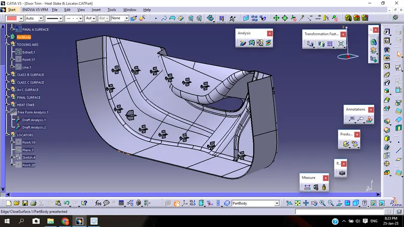
Then by using Boolean Operation unitrim Heat stake ass to part body.
Locators:-
There are following steps to creat the locater.
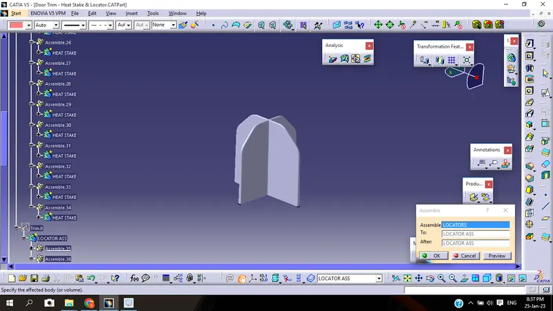
First we have to take the sketch. Then draw the two perpendicular line of length 30mm each. Take the new body name it as locator and pad it of length 30mm and thicken it to 1.3mm. Draft it for 0.5deg.
Then champher it the side edge for 7.5mm. And also edgefillet for 5deg for upper edge and 0.3deg for side edge.
Take the pionts on A surface at several distance.
Then copy the locator body and past it.
After that by using the translation command transfer the locator to another taken point.
Then take the new body and name it as Locator ass
Then by using Boolean Operation assemble all the locator in Locator ass.
Then by using Boolean Operation unitrim Locator ass to part body.
FINAL COMPONENT:-
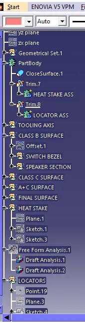
TREE STRUCTURE:-