Week 12- Final project
Aim:-
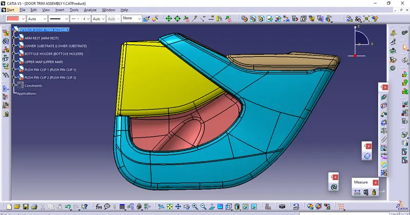
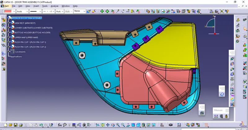
- Create the Door Trim Assembly from the given A Surface.
- Refer to the Master section design the thickness, Flanges, and Heatstakes.
- Assemble components into one single Product:
- Arm Rest
- Upper Map
- Bottle Holder
- Lower Substrate
- Push Pin Clip
ASSIGNING A SURFACE IN SINGLE PRODUCT FILE:-
- The Input file has a single Geometric set with all the surfaces of the Class A Door trim.
- We have to extract and assign the respective surfaces to each component.
- We extract the A surface for the following components:
- Arm Rest
- Upper Map
- Bottle Holder
- Lower Substrate
CREATE ASSEMBLY:-
- Collect the parts inside one assembly (Create a New Product), by either of the options:
- Copy + Paste
- Add Existing Component
- Save Management:
- We cannot directly save the file by pressing Ctrl+S, because we have to organize the parts in the assembly file folder.
File > Save Management > Select the Parent Product > Save As (Create a separate folder) > Propogate Directly.
TOOLING AXIS:-
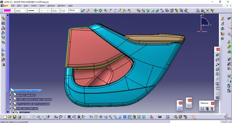
Tooling axis is the defined axis to perform the manufacturing process within the injection molding according to its direction.
CREATION OF TOOLING AXIS:-
First of all analyze the given input surface to see which direction is suitable for creating the tooling axis.
In this model to create the tooling axis we have a flat base surface and tapered side wall surfaces.
Extract the base surface from class A surface
Create a point at the center of the extracted surface.
Fix an existing perpendicular side face to the base surface as a reference to create the tooling axis.
Sketch a line using the point direction option with reference to the direction.
DRAFT ANALYSIS FOR A SURFACE:-
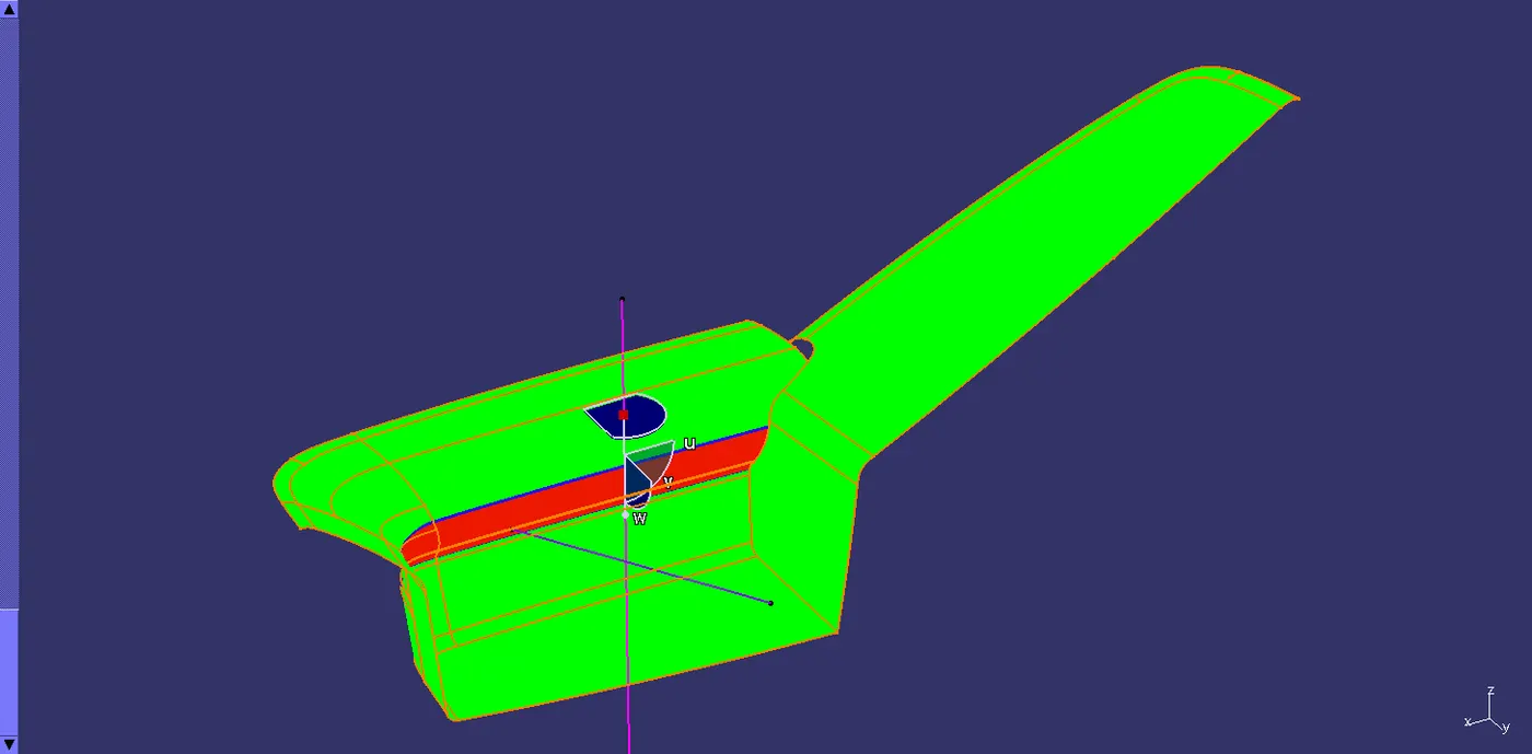
The analyzing of the model should maintain the nominal 3-degree draft angle to the tooling axis.
Draft should be given to the plastic component to reduce the wear and tear and improve the production quality and accuracy while ejecting the part from the mold cavity.
How to perform the draft analysis
1. Go to insert < analysis< feature draft analysis.
2. Align the tooling axis with a compass.
3. Click on the surface to see whether it is in permissible limit draft values or not.
4. The entire surface should be green in colour.
- Arm Rest:-
- Upper Map:-
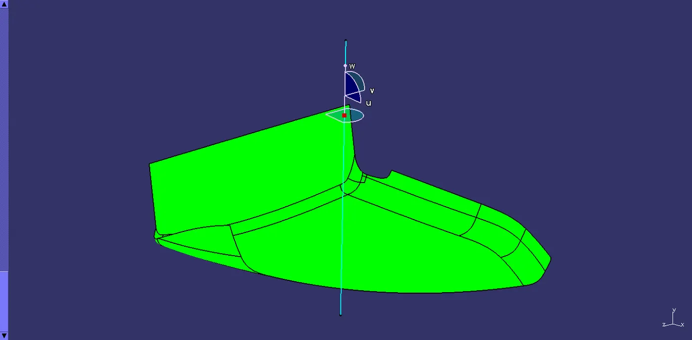
- Bottle Holder:-
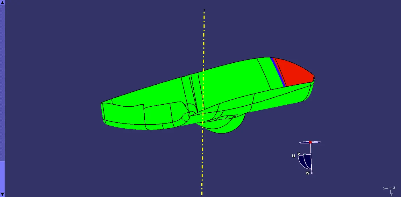
- Lower Substrate:-
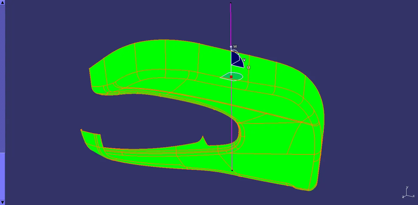
CLASS- A SURFACE:-
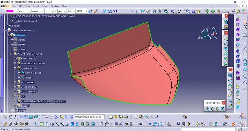
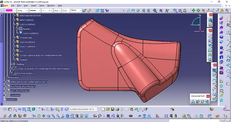
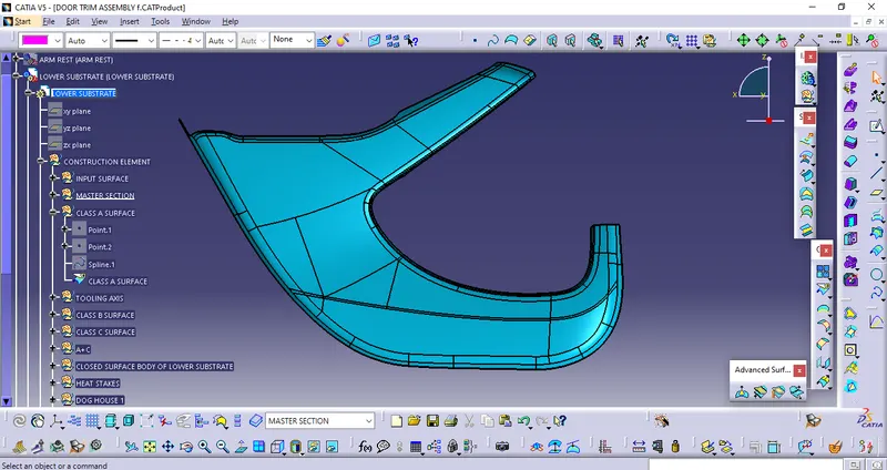
Class-A surface is given as an input surface by designers.
Generally the class-A surfaces have the tangent continuity
Class-A surface is the outermost aesthetic surface.
- Arm Rest:-
- Upper Map:-
- Bottle Holder:-
- Lower Substrate:-
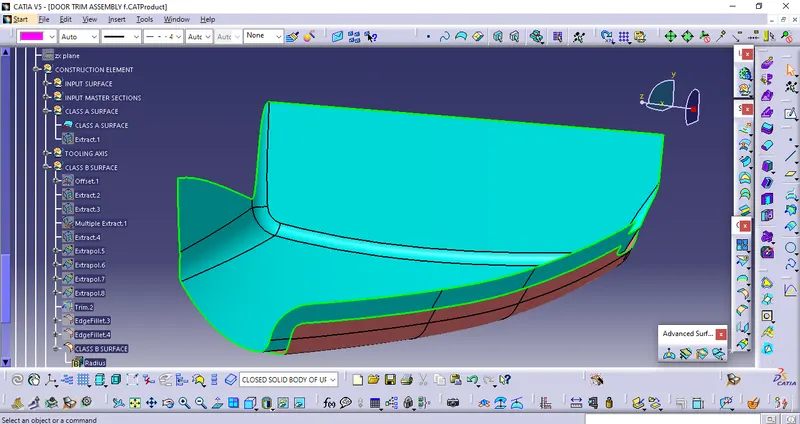
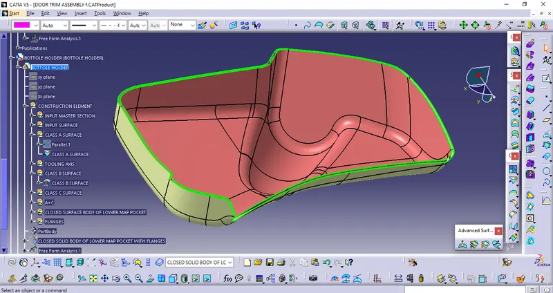
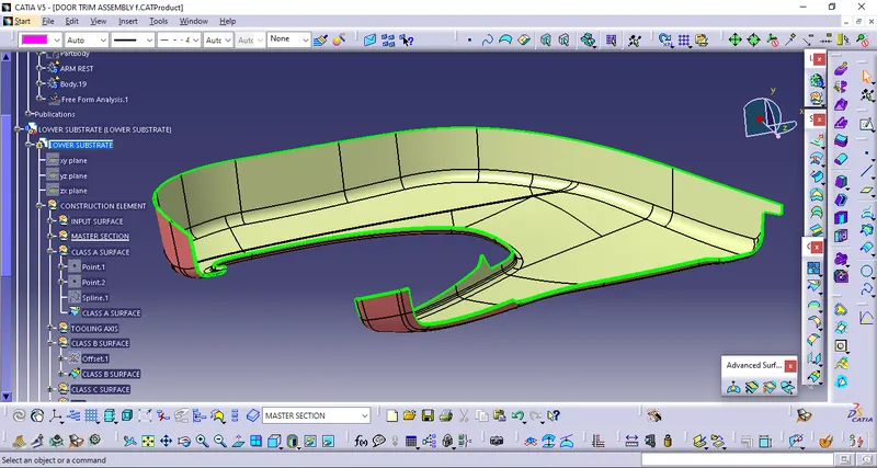
CLASS-B SURFACE:-
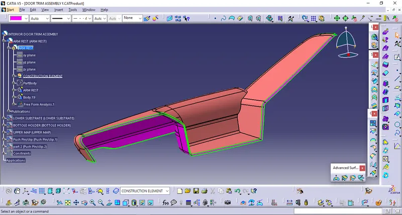
The extraction of the Class-A surface is the class-B surface.
Untrimmed the extracted surfaces from class A.
The untrimmed surfaces are offset to the required thickness. For this Challange the thickness Should be 2.5mm
After offsetting, all the surfaces are trimmed into the required shape.
Give the fillets on the edges, especially given fillet radius values should maintain the uniform wall thickness.
The class B fillet radius value=outer radius value + thickness.
- Arm Rest:-
- Upper Map:-
- Bottle Holder:-
- Lower Substrate:-
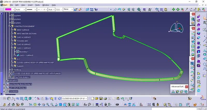
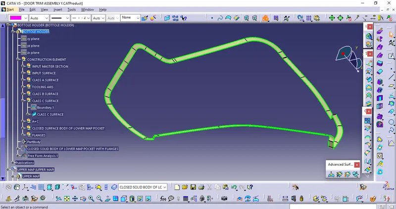
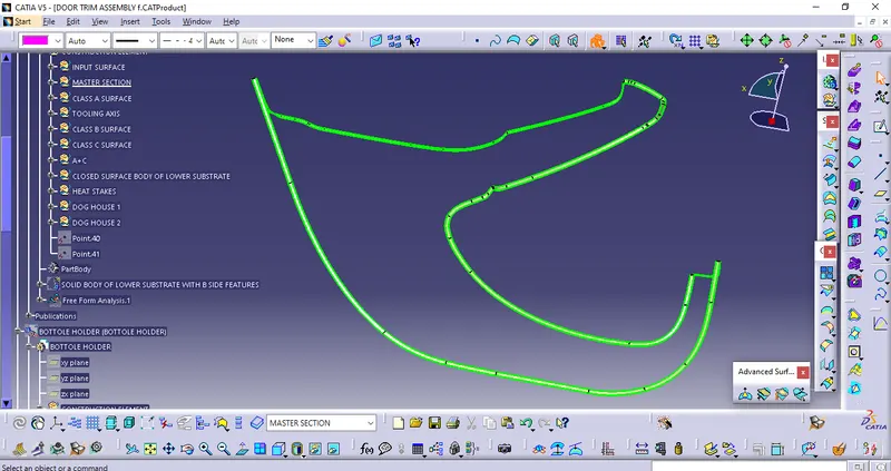
CLASS C SURFACE:-
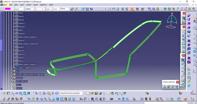
Class C surface is the closing surface of class A and class B surfaces.
It is the extraction of the boundary of class A surface.
Apply the sweep feature to create the class c surface, For guide reference click the extracted boundary and for the drafting reference option click the tooling axis and give a 3-degree draft angle.
- Arm Rest:-
- Upper Map:-
- Bottle Holder:-
- Lower Substrate:-
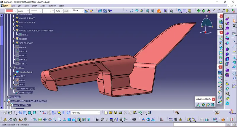
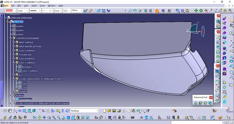
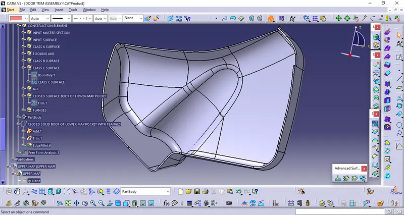
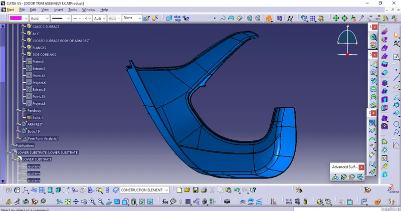
CLOSED SURFACE:-
- First Trim/Join Class A with Class C.
- Then Trim with Class B and keep the respective surfaces.
- Arm Rest:-
- Upper Map:-
- Bottle Holder:-
- Lower Substrate:-
CLOSED BODY DRAFT ANALYSIS:-
All the 3 class surfaces must pass in this analysis.
Insert > Analysis > Feature Draft Analysis.
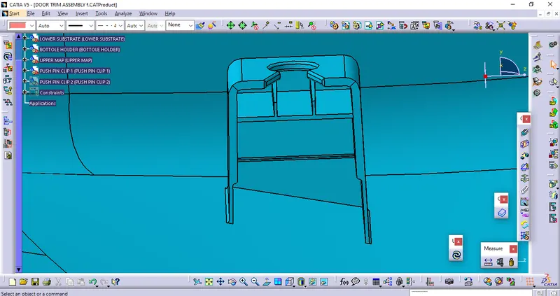
DOG HOUSE DESIGN:-
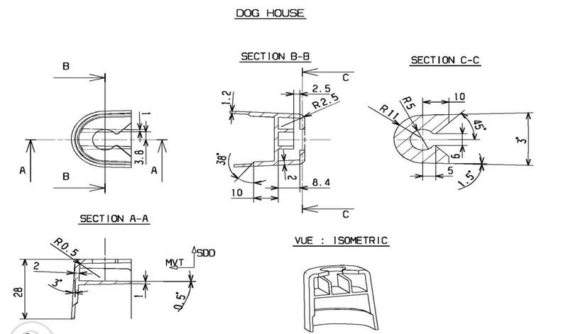
Dog house is an engineering feature used in plastic trim design. Dog houses are used as supporting feature. Sometimes other engineering features like snaps; locators etc. are mounded on them to increase their strength. It is subjected to draft analysis to prevent breakage of the component during ejection from mould cavity. Dog house and other engineering components are built on B-surface.
To creat dog house the following steps to be followed.
First we have to creat the plane so that we can take the sketch. Then we have to draw the rectangle on it. Then pad it to certain limit. After that draft it at certain angle. Then use shell comand to remove one surface. For shell give the thickness of 2mm.
After that we have to generate the wall thickness(C) and height (B).
For that first we have to extract the base surface then offset it for the setain limit. Then we have to take the inner surface of shell witch we have created and offset it for 0.4*wall thickness. After that we have to trim both the offset.
Then give the edgefillet where it is required and also the draft command.
After that use the split comand between the shell and the above trim.
Then by using Boolean Operation we have to trim it with solid body.
The following design rules should follow given below.
Doghouse wall thickness at the intersection of the part wall ( C ) should be 40% or less than the main wall stock ( T ).
The height of ( B ) should be between 3.0 – 6.0 mm.
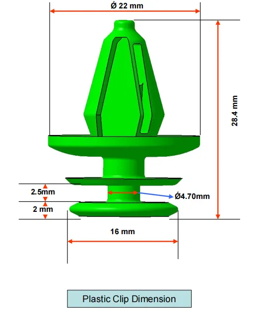
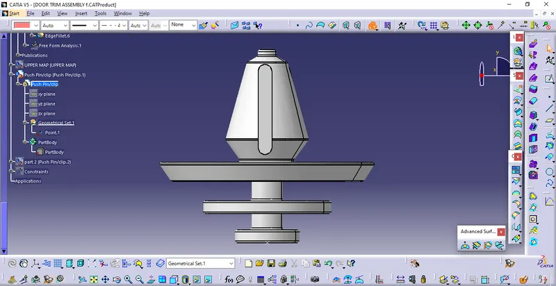
PLASTIC FEATURE: PUSH PIN:-
It is a feature that facilitates:
- Locating and Arresting components of an Assembly.
- Providing Alignment in Mating Parts.
- Acting as a stopper or guide for various mechanisms.
HEAT STAKE:-
Heat staking also known as thermoplastic staking is the process of joining two dissimilar materials together.
There are following steps to generate heat stake.
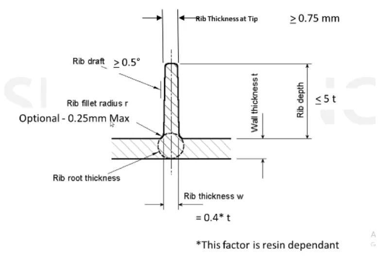
- There are no standards for Dia, it depends on the manufacturer.
- The dimension is altered in such way that sink marks are avoided.
- There is no standard for thickness as well, but keep it lesser than the part thickness.
- Minimum 0.75mm at the Tip of the Rib.
- Height of Heatstake < Height of Locator
- Since Fixing occurs after Locating.
- 0.5 degree.
- Dia of Flat Plate = 2.5 x (Dia of Heat Stake).
- 0.1mm to accommodate for clearance.
- Space between the two heat stakes must be 65-100 mm
Operations to be followed:-
First we have to take the sketch. Then draw the two circle of diameter given in master. Take the a new 1body and pad the circle of length 20mm.
Then take another sketch and draw two perpendicular line of length 24mm each. Take the new 2body and pad it of length 15mm and thicken it to 1mm. Draft it for 0.5deg.
Then by using Boolean Operation unitrim 2body with 1body and rename it as heat stake.
Take the pionts on A surface at several distance.
Then copy the heat stake part body and past it for several time.
After that by using the translation command transfer the heat stake to another point.
Do the above step for every point.
Then take the new body and name it as Heat stake ass
Then by using Boolean Operation assemble all the heat stake in Heat stake ass.
Then by using Boolean Operation unitrim Heat stake ass to part body.
BOOLEAN OPERATION:-
- We have to add all the translated features to the Main body of the Substrate.
- The Union Trim operation fit the best option for our needs.
- Define the Main part body as the Working Object.
- Select Feature Body > Union Trim > Select Faces to remove/keep
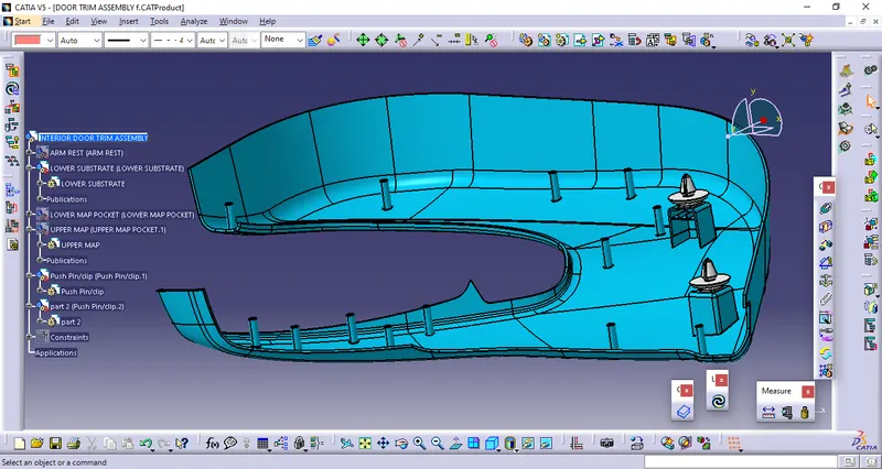
CLEARANCE FOR HEAT STAKES PROVIDED ON FLANGES:-
- The door trim Assembly has to be rigidly fixed as one unit.
- The 4 components will be permanently arrested to the Lowered substrate by using the Heastakes.
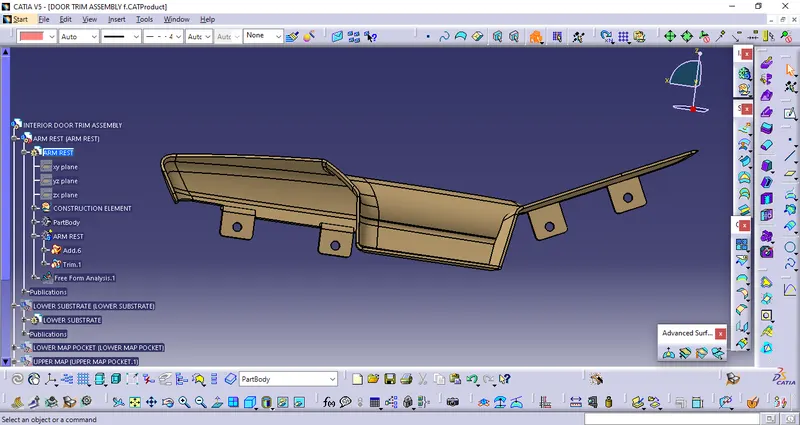
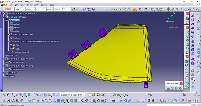
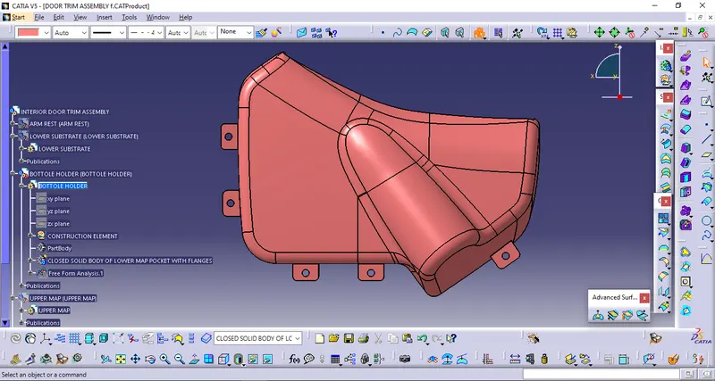
- The Heatstakes will pass through the flanges of the components, therefore some clearance of 0.1mm has to be provided.
- Arm Rest:-
- Upper Map:-
- Bottle Holder:-
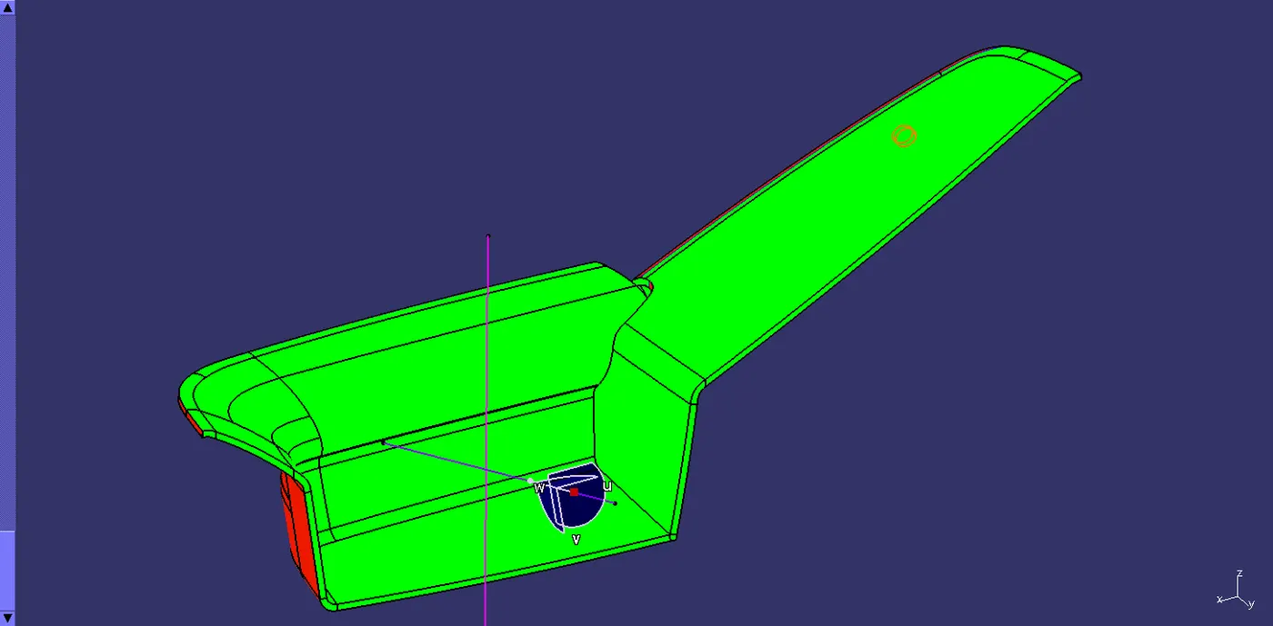
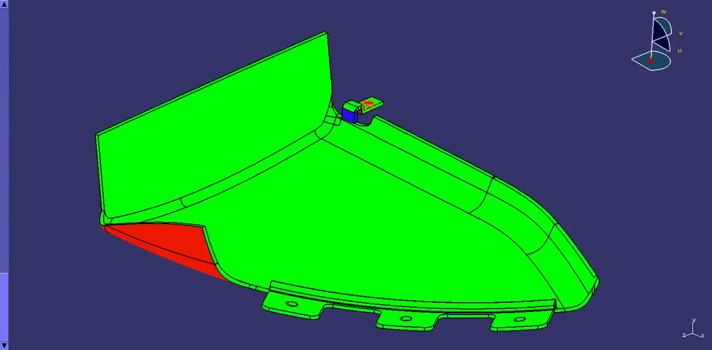
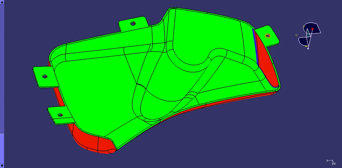
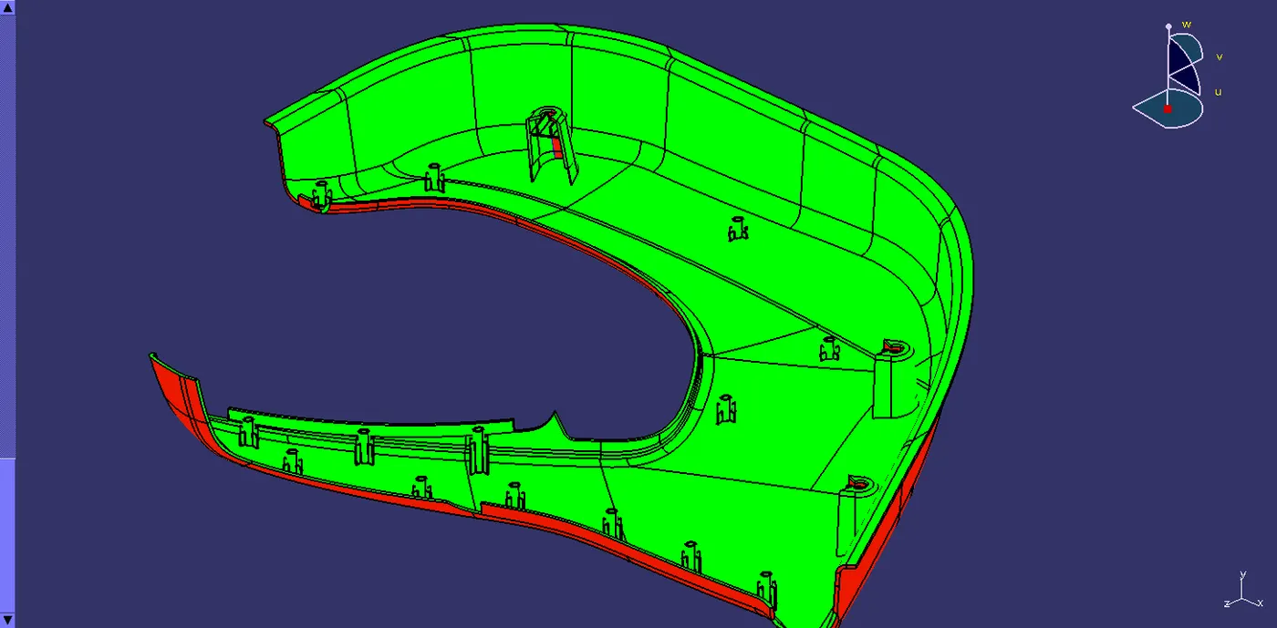
FINAL DRAFT ANALYSIS:-
Insert > Analysis > Feature Draft Analysis
Note: Ensure you have the Material view mode ON.
- Define the Draft direction using the "Compass" option.
- Drag the Axis system representation close to the model and align it along the tooling axis.
- "Lock" the Draft direction.
- Set the Colour scale.
- Arm Rest:-
- Upper Map:-
- Bottle Holder:-
- Lower Substrate:-
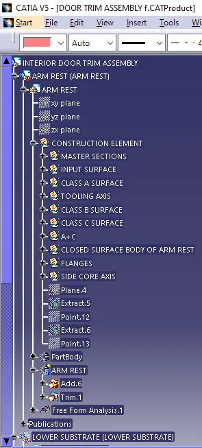
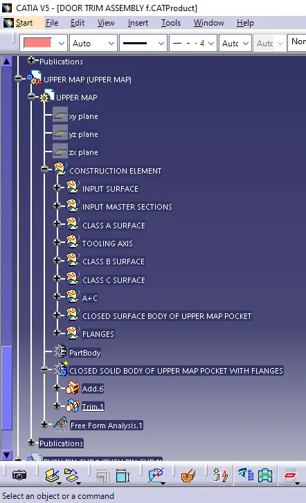
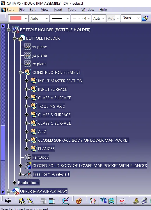
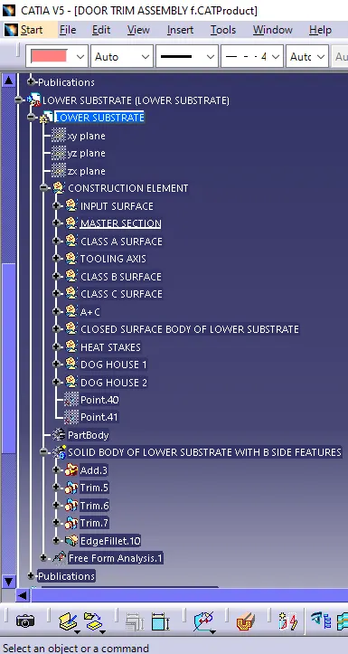
TREE STRUCTURE:-
- Arm Rest:-
- Upper Map:-
- Bottle Holder:-
- Lower Substrate:-
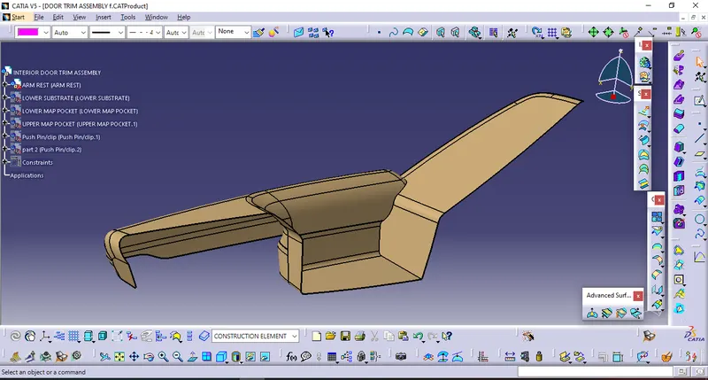
FINAL LOOK OF DOOR TRIM ASSEMBLY:-