Week 8 - Challenge 6 - Core & Cavity Design
AIM:-
To make the Core and Cavity Design
In this model we have to consider the following things:-
Tooling axis
Draft analysis
Class-A surface
Class- B surface
Class-C surface
Core Cavity Design
Making a solid model from the surface.
TOOLING AXIS:-
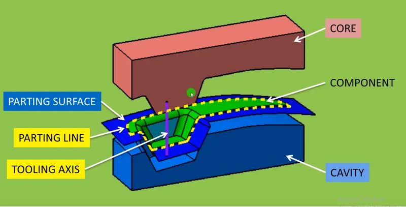
Tooling axis is the defined axis to perform the manufacturing process within the injection molding according to its direction.
CREATION OF TOOLING AXIS:-
First of all analyze the given input surface to see which direction is suitable for creating the tooling axis.
In this model to create the tooling axis we have a flat base surface and tapered side wall surfaces.
Extract the base surface from class A surface
Create a point at the center of the extracted surface.
Fix an existing perpendicular side face to the base surface as a reference to create the tooling axis.
Sketch a line using the point direction option with reference to the yz direction.
Final sketched line is called as tooling axis.
DRAFT ANALYSIS:-
The analyzing of the model should maintain the nominal 3-degree draft angle to the tooling axis.
Draft should be given to the plastic component to reduce the wear and tear and improve the production quality and accuracy while ejecting the part from the mold cavity.
How to perform the draft analysis
1. Go to insert < analysis< feature draft analysis.
2. Align the tooling axis with a compass.
3. Click on the surface to see whether it is in permissible limit draft values or not.
4. The entire surface should be green in colour.
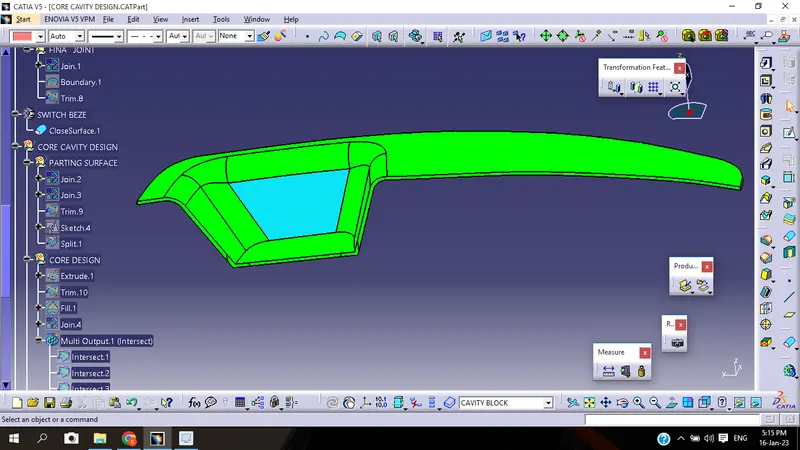
CLASS- A SURFACE:-
Class-A surface is given as an input surface by designers.
Generally the class-A surfaces have the tangent continuity
Class-A surface is the outermost aesthetic surface.
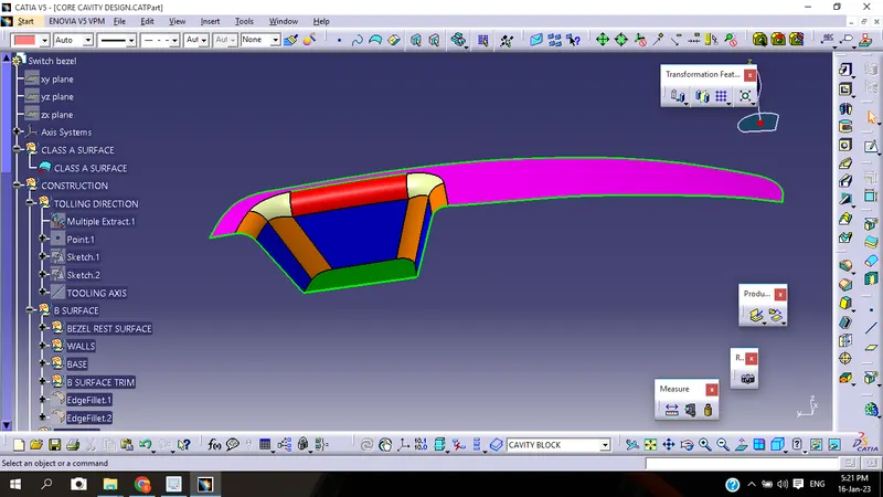
CLASS-B SURFACE:-
The extraction of the Class-A surface is the class-B surface.
Untrimmed the extracted surfaces from class A.
The untrimmed surfaces are offset to the required thickness.
After offsetting, all the surfaces are trimmed into the required shape.
Give the fillets on the edges, especially given fillet radius values should maintain the uniform wall thickness.
The class B fillet radius value=outer radius value + thickness.
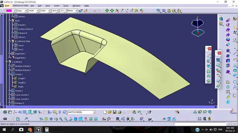
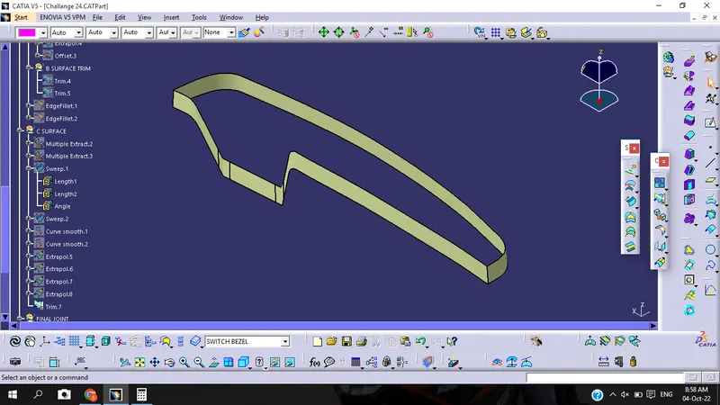
CLASS C SURFACE:-
Class C surface is the closing surface of class A and class B surfaces.
It is the extraction of the boundary of class A surface.
Apply the sweep feature to create the class c surface, For guide reference click the extracted boundary and for the drafting reference option click the tooling axis and give a 3-degree draft angle
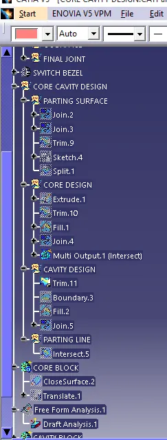
CORE CAVITY DESIGN
In this model we have to consider the following things:-
- Partning Surface
- Core Design
- Cavity Design
- Partning Line
PARTNING SURFACE:-
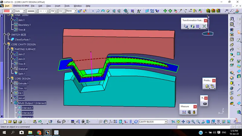
Partning Surface is a surface which acts as connect between the the core and cavity.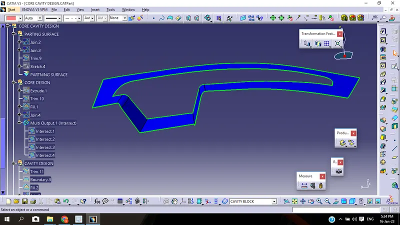
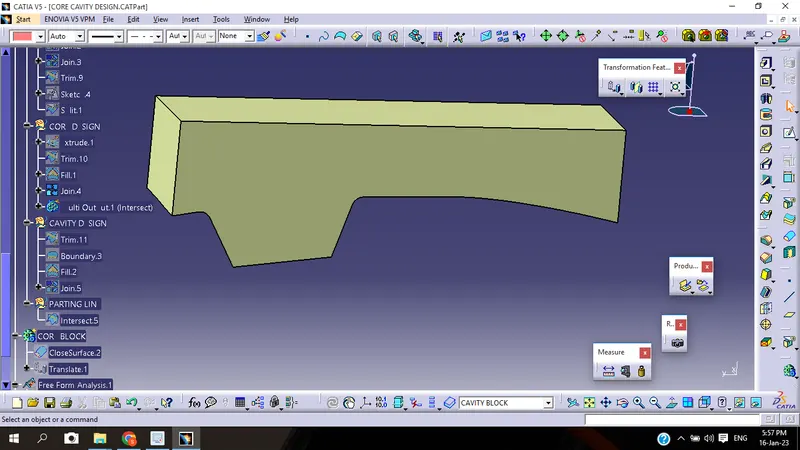
CORE DESIGN:-
Core is the upper or top part of the mold. Cores are frequently used to create hollow sections or cavities in a casting. A core is a preformed, bonded, sand insert placed into the mold to shape the interior of a casting or a part of the casting that cannot be shaped by the pattern
For designing the core first we have to extrude the rectangle to a certan limit in upper direction. Then we have to trim it and then apply the fill comand at the top. After that we have to joint the fill and trim together.
Apply the close body comand by going in the part body to put in solid portion.
CAVITY DESIGN:-
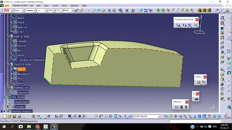
Cavity is the lower part of the mold. Cavity is the upper half of the injection mold usually the show surface of the finished product but is mainly concave.
For designing the cavity the process is same as the core design but in downward direction.
First we have to extrude the rectangle to a certain limit in the downward direction. Then we have to trim it and then apply the fill comand at the bottom. After that we have to joint the fill and trim together.
Apply the close body comand by going in the part body to put in solid portion.
After designing the core and cavity ther is some gape between the core and cavity where the molten plastic is filled.
PARTNING LINE:-
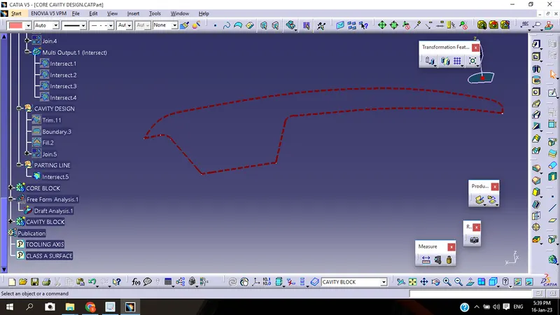
Parting line is the intersection between the parting surface and the component where the core and cavity splits together from each other. It is an imaginary line.
FINAL COMPONENT:-
TREE STRUCTURE:-