Wiring harness routing & packaging Rules Week 3 Challenge
AIM:
- To solve the above assignment questions and define the necessary electrical properties in the respective workbench.
- Prepare the catalogue for the same.
INTRODUCTION:
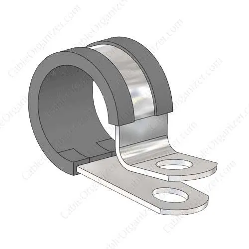
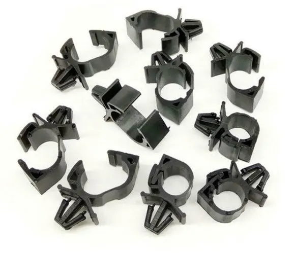
Cable clamps are accessories for wire and cable. They are used to bundle, clip, clamp, label, guide, and protect wires and cables. Clamps play an important role in the installation and maintenance of cable systems. Cable clamps are used in home construction, automotive, rigging, and many more industrial and manufacturing applications. The clamps are available in a wide variety of types and sizes.
The shape and size of the item or system being secured. The maximum diameter refers to the maximum diameter of the bundle of wires and cables. If the clamp is larger than the conduit foreign matter can enter the space between the two pieces can cause damage due to abrasion. If the conduit is larger than the clamp deformation and strain can occur on the mounting foot of the clamp and potentially break the clamp.
BACKSHELLS
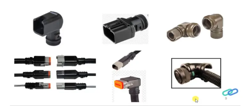
In general, connector back shells fall under the classification as ‘connector accessories. Back shells are the components that attach to the back of connectors often designed to guide the wires and cables that are terminated at the connector. The back shells are often mated with strain relief components, environmental seals, the shielding. The back shell may be made from metal or moulded using a rubber or neoprene covering over the back shell of the connector.
In other words, backshells are plastic moulded parts used at the wire entry side of the connectors either for protection or to improve the aesthetics/appearance of the harness. These are not mandatory parts of wiring harness and are always optional and driven by cost.
Corrugated tubes
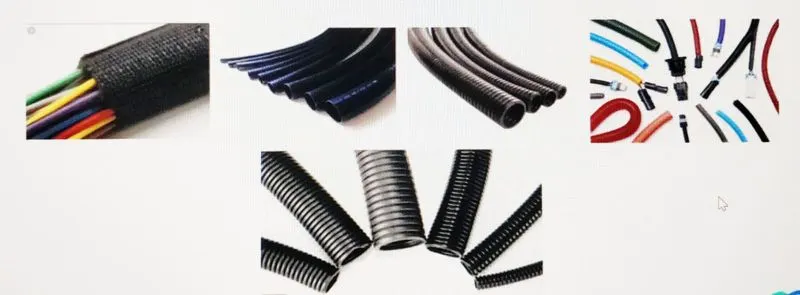
Corrugated tubes, convolutes, sleeves and many other types of coverings ae used to protect the wiring harness. Graphical representation of coverings is applied on bundles.
Corrugated conduits and protective hoses with various properties, from heat resistance through abrasion protection and impact strength to noise reduction, protect valuable cables against all unfavourable external influences.
OBJECTIVE:
- To download the P-Clamp CAD data and define it as Electrical Support in the Electrical Part design workbench and also define the necessary electrical properties.
- To download the Backshell CAD data and define it as Electrical Back shell in the Electrical Part design workbench and also define the necessary electrical properties.
- To create Following Corrugated tubes and add them in Catalogue under “Slit COT” family.
|
Name |
ID (mm) |
OD (mm) |
Thickness (mm) |
|
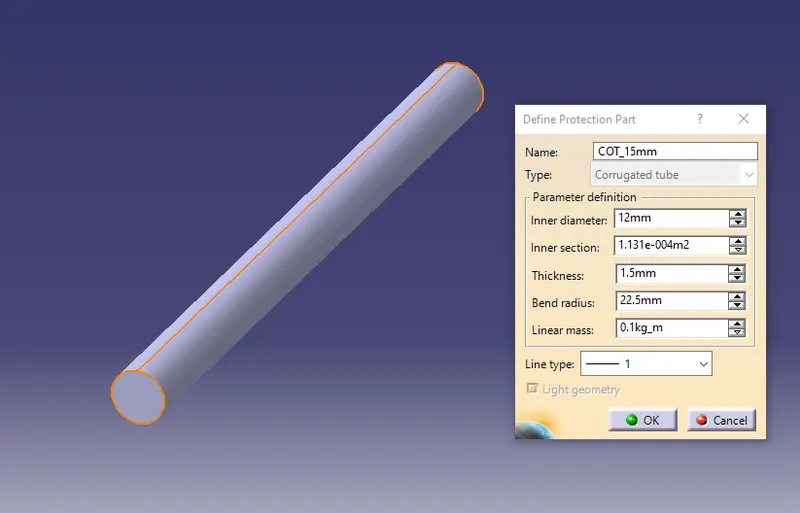
15mm COT |
12 |
15 |
1.5 |
|
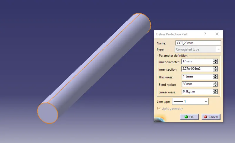
20mm COT |
17 |
20 |
1.5 |
|
35mm COT |
32 |
35 |
1.5 |
|
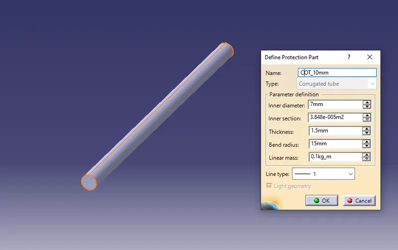
10mm COT |
7 |
10 |
1.5 |
|
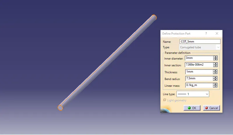
5mm COT |
3 |
5 |
1 |
DESIGN METHODOLOGY:
1. P - CLAMP:
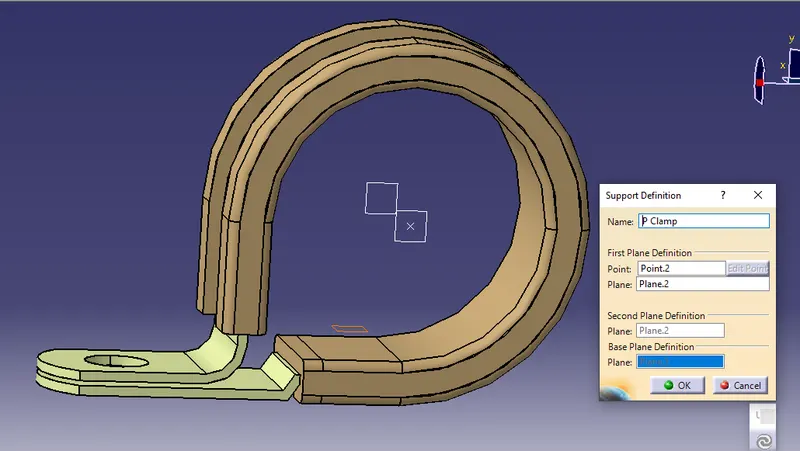
- P-Clamp is an Electrical Support equipment which provides support to the wire bundle to remain fixed to the automobile or any components or parts.
- The wire bundle can enter and exit from any side as it is a bi-directional equipment.
- So, we need to specify the Entry and Exit points from both the sides.
- To define the P-Clamp as Electrical Support equipment we need to follow the below steps:
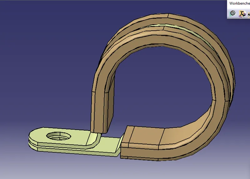
Step - 1:
- First download the CAD part and open it using the CATIA V5 software.
Step - 2:
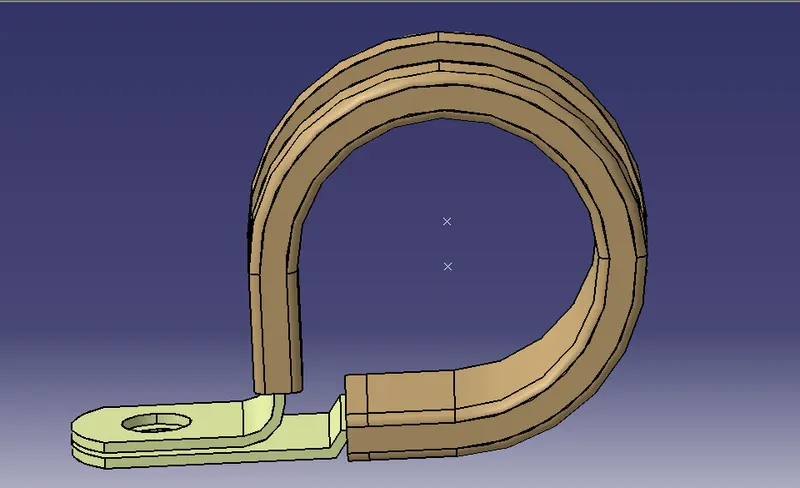
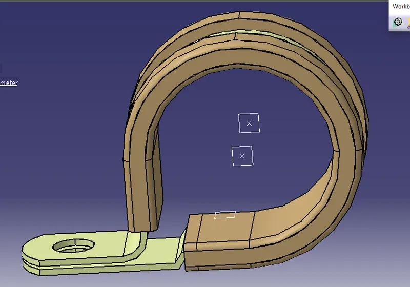
- Now we have to define the geometry parameters.
- In order to define the geometry parameters, we need to navigate to the Part Workbench.
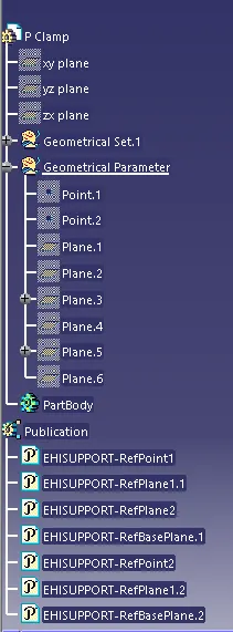
- Then we need to create points and plains at the entry and exit points.
Step - 3:
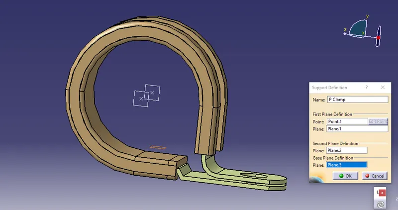
- Now in order to define the P-Clamp as a Electrical support we have to navigate to the Electrical Part design Workbench.
- Now using the 'Define support part' option we can define the P-Clamp Entry and Exit points.
- As the P-Clamp is Bi-directional so we need to define the support two times.
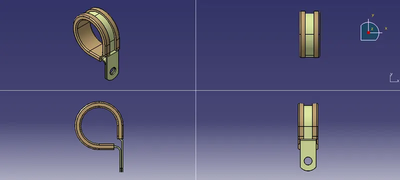
3D Part model in various orientations (Isometric, Front, Side, and Top View):
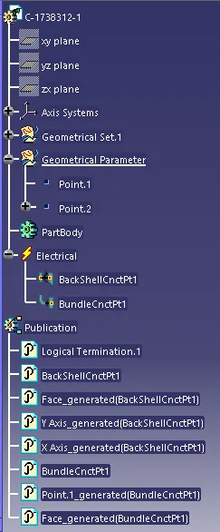
TREE STRUCTURE:
2. BACKSHELL
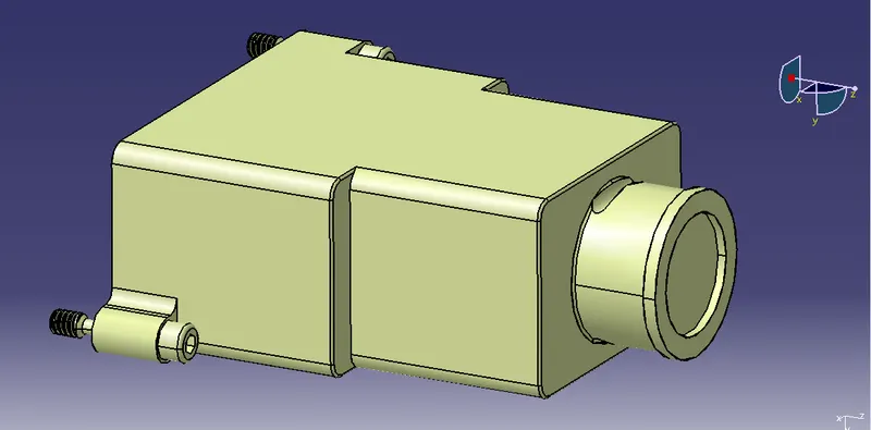
- A backshell is an accessory that mounts to the rear threads of a connector to enhance its operational characteristics. The primary function of a backshell is to provide strain relief, which minimizes stress from the cable, on the junction where the wires terminate to the contacts.
- Backshells come in a variety of finishes, materials, and angle configurations. For material compatibility and aesthetics, backshells and connectors should have a matching material and finish. And to provide simple cable management, most backshells may be ordered in 45º and 90º angles.
- To define the Electrical properties of the backshell we need to follow the below steps:
Step - 1:
- First download the 3-D CAD part of the backshell and open it using the CATIA V5 software.
Step - 2:
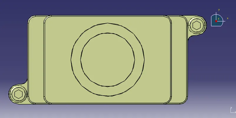
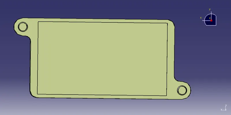
- Identify from which side the bundle will enter and the side which will mate with the connector.
Bundle Entry Side:
Connector mating side:
Step - 3:
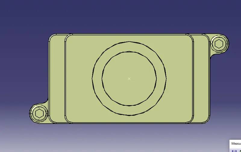
- Create mid-point at the bundle entry side.
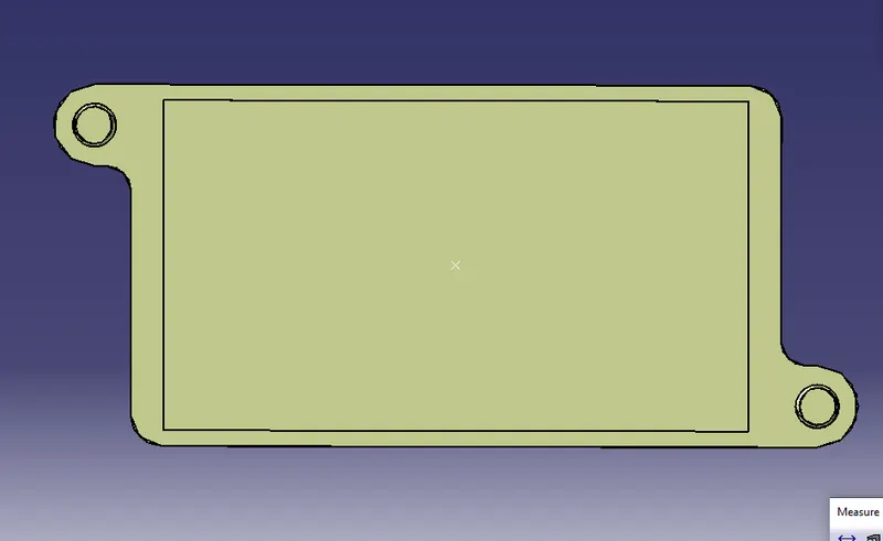
- Create mid-point at the connector mating side.
Bundle entry side:
Connector mating side:
Step - 4:
- Create an Axis system at the Connector mating side.
- The axis system should be created at the center of the mating surface.
- The axis must be defined as defined for the connectors show that it will connect easily.
- Y- axis: Normal to the mating surface
- X-axis: Normal to the locking side
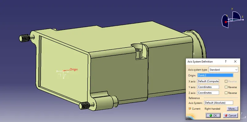
Step - 5:
- To define the Electrical properties, we need to navigate to the Electrical Part design workbench.
- There we need to define the component as the 'Backshell'.
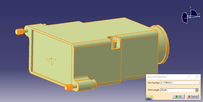
Step - 6:
- Define the Backshell connection point.
- Then define the Bundle connection point.
Backshell Connection Point:
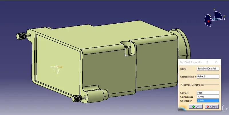
Bundle Connection Point:
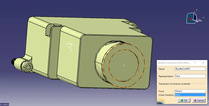
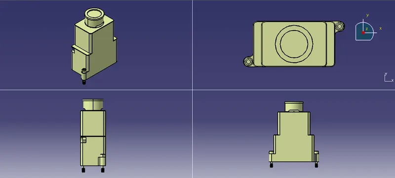
3D Part model in various orientations (Isometric, Front, Side, and Top View):
TREE STRUCTURE:
3. CORRUGATED TUBES:
- Corrugated Tubes are used as protection coverings for the wire bundle from any type of damages.
Step - 1:
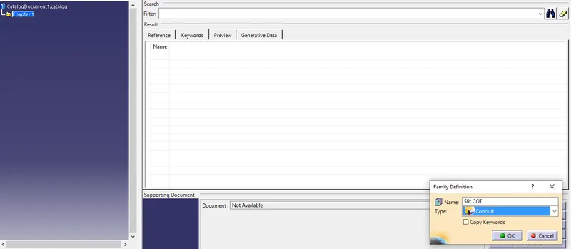
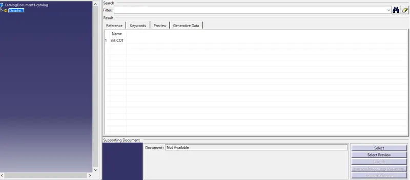
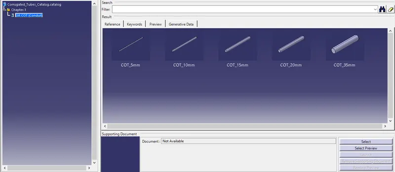
- Create a Catalogue document and adding Slit COT as a family and saving the document in our desired folder.
Step - 2:
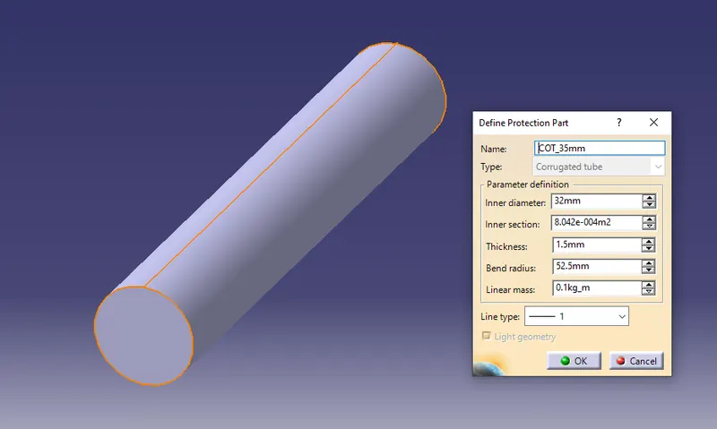
- Creating the following corrugated tubes as per the dimensions given in the table and storing in the Slit COT family catalogue document.
|
Name |
ID (mm) |
OD (mm) |
Thickness (mm) |
|
15mm COT |
12 |
15 |
1.5 |
|
20mm COT |
17 |
20 |
1.5 |
|
35mm COT |
32 |
35 |
1.5 |
|
10mm COT |
7 |
10 |
1.5 |
|
5mm COT |
3 |
5 |
1 |
1. 5 mm COT TUBE:
2. 10 mm COT TUBE:
3. 15 mm COT TUBE:
4. 20 mm COT TUBE:
5. 35 mm COT TUBE:
CORRUGATED TUBE CATALOGUE:
CONCLUSION:
- From the above assignment we learnt how to define the Electrical support for a P-Clamp and also define its Electrical properties.
- We also learnt how to Electrical Backshell for a Backshell component and also define its Electrical properties.
- We also learnt how to make Corrugated Tubes of different diameters and also save them in the respective families in the Corrugated Tubes catalogues.