Week 7 Challenge - Assembly Workbench
Aim:
- To create the quick return mechanism assembly modeling and cv axle joint assembly modeling in the assembly workbench using catia v5.
Steps in assembly modeling:
Entering the assembly design work bench:
- You can only select the workbenches that show up on the "welcome to catia" window. by default, the assembly design workbench will not show up in this window, so you will need to use the other method, the start menu.
- To create an assembly, the first thing to do is enter the assembly design workbench. to do this, select the start pull- down menu from the top of the screen.
- From the start pull-down menu, select the mechanical design option. Rom the mechanical design menu, select the assembly design option. this will bring you to the assembly design workbench.
Inserting components into the assembly design work bench:
- Before the detailed parts can be assembled, you will need to insert them into the assembly workbench. the following steps explain how this is done. the top of the specification tree must be selected before components can be inserted into assembly design workbench.
- In this case, the top of the specification tree is labeled is 'product 1'.
- If your specification tree has a different number following the "product", it is ok; the process is the same. we have entered the assembly design workbench. with "product" highlighted, select the existing component tool and insert an existing component window that will appear on the screen.
Activating the assembly product:
Fix the parent part and then assemble the other subparts with respect to the parent part using the assembly constraints:
Assembly constraints: coincidence constraint:
Coincidence-type constraints are used to align elements click the coincidence constraint icon select the face to be constrained. select the second face to be constrained. green arrows appear on the selected faces, indicating orientations. click ok to create the coincidence constraint.
- Contact constraint:
Contact-type constraints can be created between two planes or faces. the common area between the two planes can be a plane (plane contact), a line (line contact), or a point (point contact). click the contact constraint icon. select the face to be constrained. select the second face to be constrained.
As the contact constraint is created, the component is moved so as to adopt its new position.
Green graphic symbols are displayed in the geometry area to indicate that this the constraint has been defined.
- Offset constraint:
When defining an offset constraint between two components, you need to specify how faces should be oriented. click the offset constraint icon.
Select the face to be constrained.
Select the second face to be constrained.
- Angle constraint:
Angle-type constraints fall into three categories:
Angle.
Parallelism.
Perpendicularity.
When setting an angle constraint, you will have to define an angle value. note that this angle value must not exceed 900. click the angle constraint icon. select the face to be constrained select the second face to be constrained. keep the angle option. enter values in the angle field.
Click ok to create the angle constraint.
Final assembly images:
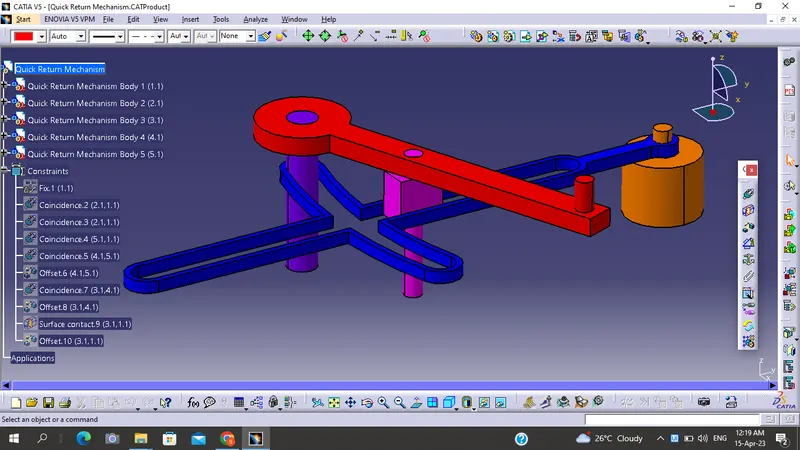
Quick Return Mechanism Assembly:
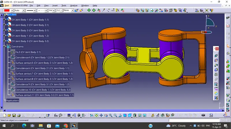
CV Joint Assembly: