Motion Analysis of a Planetary Geartrain
Aim: The goal of the project is to conduct a multi-body simulation on a Planetary geartrain in solidworks.
Background:
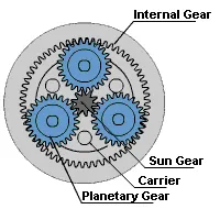
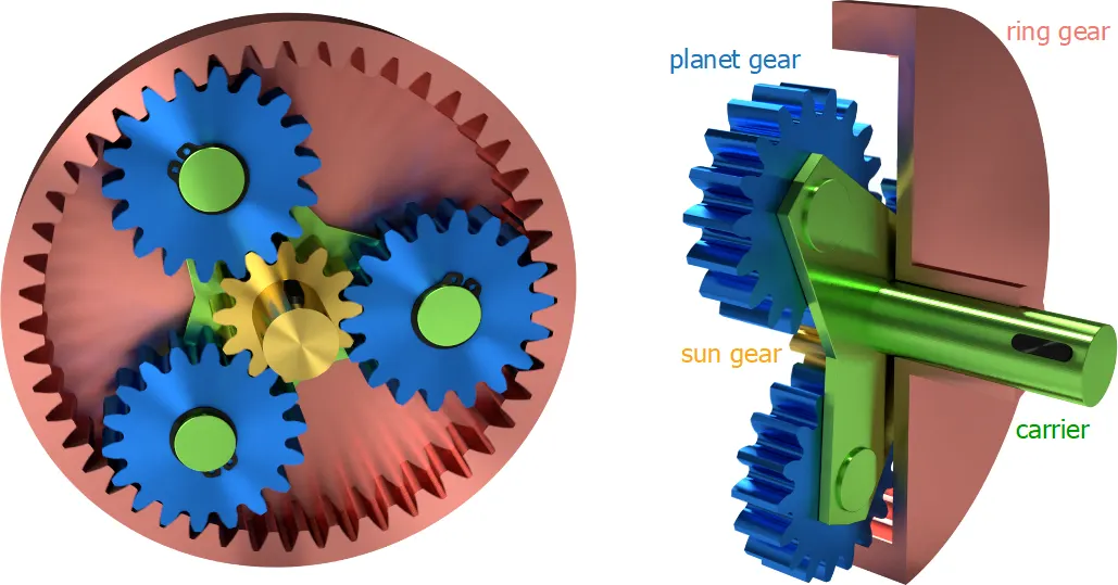
A planetary gear train, also known as an Epicyclic geartrain, consists of two gears mounted so that the center of one gear revolves around the center of the other. A carrier connects the centers of the two gears and rotates to carry one gear, called the planet gear or planet pinion, around the other, called the sun gear or sun wheel. The planet and sun gears mesh so that their pitch circles roll without slip. A point on the pitch circle of the planet gear traces an epicycloid curve.
Various torque ratios are arrived at keeping parts of the geartrain fixed. For instance, the ring could be fixed and the output could be taken from the carrier while input is provided to the sun. A different torque could be obtained if the carrier is fixed and the ring is the output. The fixing of respective systems is often done with a combination of clutches and is engaged either manually by the driver (in a car) or automatically based on torque requirements.
In this simulation, we are looking at the following 3 cases:
| Sl. No. | Input | Fixed | Output |
| 1 | Sun | Ring | Carrier |
| 2 | Ring | Sun | Carrier |
| 3 | Sun | Carrier | Ring |
Procedure:
- Teeth calculation:
- Radius of ring = 2 x radius of planet + radius of sun -> Dp = Rr - Rs
- Pitch circle Diameter of ring -> dr = m x z = 2.5 x 46 = 115 mm
- Module stays the same for all gears in mesh.
- PCD of sun = 2.5 x 14 = 35 mm
- Dp = Rr - Rs
Dp = 115 - 35
Dp = 40 - Zp (number of teeth on planet) = 40 / 2.5
Zp = 16
-
Sl. No. Gear Teeth PCD (mm) 1 Sun 14 35 2 Ring 46 115 3 Planet 16 40 - Use the Design Library-> Toolbox -> ANSI Metric -> Power Transmission -> Gears to insert one internal spur gear and 5 spur gears based on the modules, diameter, and teeth calculated above.
- Face width: 12 mm
- Pressure angle: 20 degrees
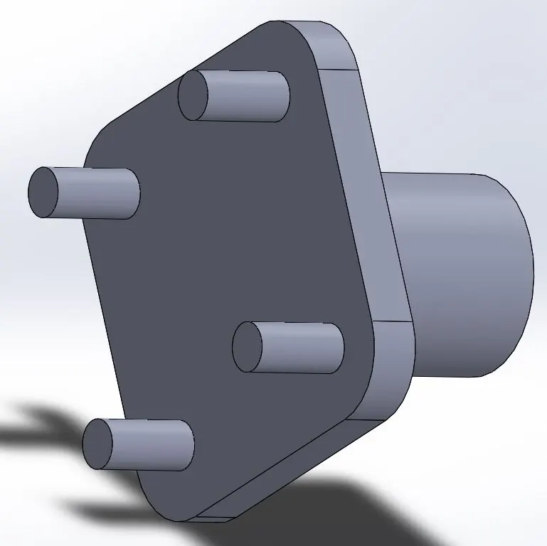
- Model the carrier taking shaft dimensions as taken during planet modeling and pitch circle diameters of the planet. Carrier should resemble the one below:
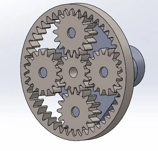
- Once inserted, create the assembly by aligning the faces of the gears and making the axes coincident. The final result should look as follows:
- Run the MBD in 3 aforementioned cases by fixing the respective gears.
- RPM = 200
- Material -> Steel (Dry)
- Generate the plot of the angular velocity of the output component vs Time.
Output-> Angular Velocity vs Time plots:
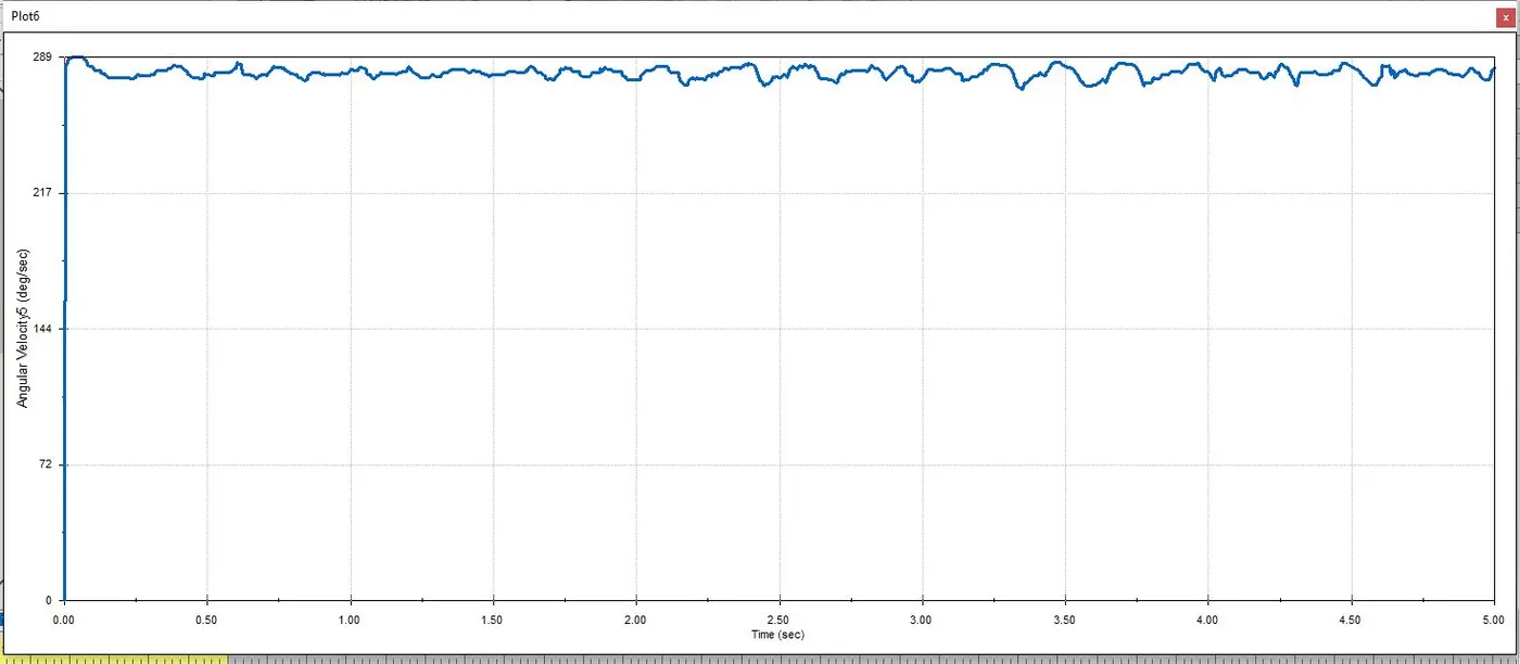
Case 1-> Input to Sun, Fixed Ring, Output from Carrier:
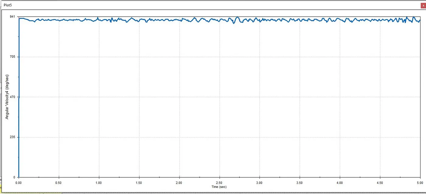
Case 2-> Input to Ring, Fixed Sun, Output from Carrier:
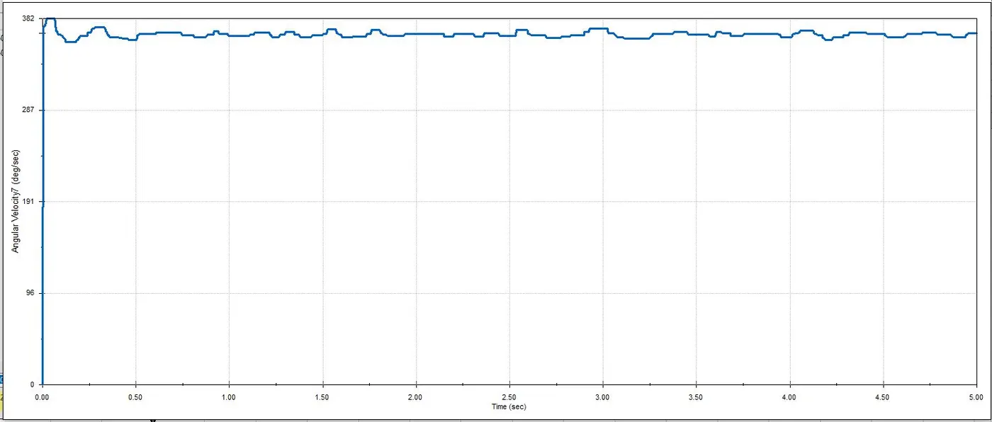
Case 3-> Input to Sun, Fixed Carrier, Output from Ring:
Conclusion:
First case-> With the Ring fixed, power transmission is happening from the sun gear to the planets, which is going from a 14 teeth gear to a 16 teeth gear. Since the difference is small, the multiplication is small and hence the angular velocity is lower as well at 289 deg/s.
Second case-> With the Sun fixed, the planets are both rotating and revolving inside the ring, which in itself is receiving input and rotating slowly. The ring is large and has 46 teeth, there is large speed multiplication happening, hence the angular velocity is high at 941 deg/s.
Third case-> With the carrier fixed, the only motion is the rotation of the planets, which translates to a smaller motion of the ring. Hence, the angular velocity is lower here as well at 382 deg/s.