Internal Geneva Mechanism
Aim: To create the CAD model of Internal Geneva mechanism and to study the motion analysis for obtaining contact force and angular displacement.
Geneva Mechanism:
Geneva mechanism is commonly used indexing mechanism where an intermittent motion is required. The design and fabricating of a conventional Geneva mechanism is generally simple and inexpensive because there is no specially curved profile on any of the components except the straight lines and circular arcs.
But due to discontinuity of the acceleration at the beginning and ending positions the use of conventional Geneva mechanism is having the large impact when the driving crank engages and disengages with the wheel slot.
Advantages of Geneva Mechanism:
- Geneva mechanism is the simplest and least expensive of all intermittent motion mechanisms.
- They come in a variety of sizes.
- They have good motion curves characteristics compared to ratchets.
- Geneva always maintains excellent control of its load since it is provided with locking ring surfaces.
Disadvantages of Geneva Mechanism:
All Geneva acceleration curves starts and end with finite acceleration and deceleration, therefore they produce a little jerk.
Types of Geneva Mechanism:
- External Geneva Mechanism:
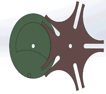
In this external Geneva mechanism, the driven wheel is externally connected with a rotating drive wheel. It is most popular and commonly used in watches and film projectors.
- Internal Geneva Mechanism:

In the internal Geneva mechanism, the driven wheel is internally connected with a rotating drive wheel. Its disadvantage is that it cannot be made small, and it cannot withstand high mechanical stresses like External Geneva drives.
- Spherical Geneva Mechanism:
In Sphe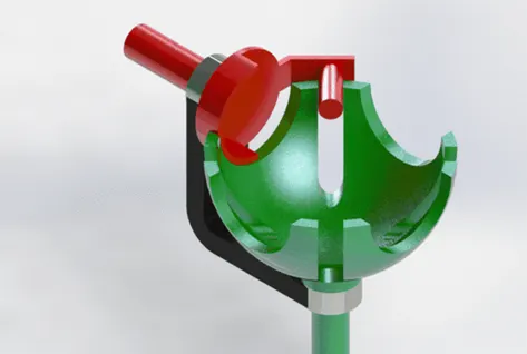 rical Geneva mechanism, the driven wheel is spherical in shape and is externally connected to the rotating drive. In this, driving and driven wheels are on vertical shafts, i.e., Input and Output shafts are perpendicular to each other.
Procedure:
Given Drawings:
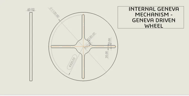
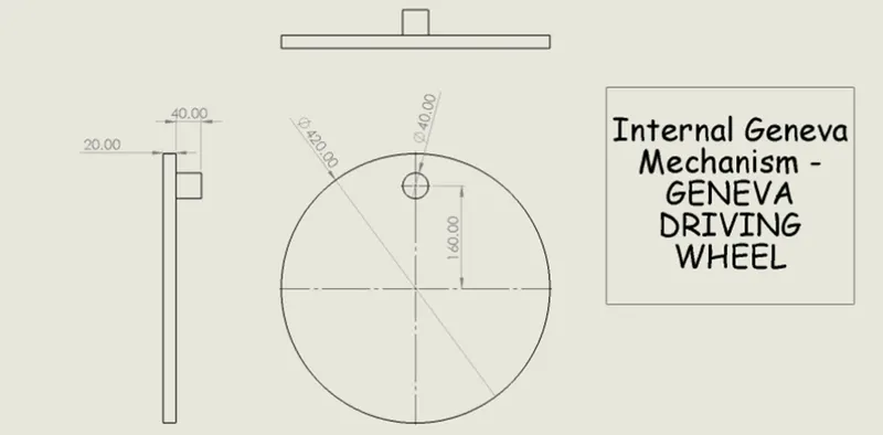
To create the 3D Model of Driving and Driven Wheels from the given 2D drawings in SolidWorks for the motion analysis of Internal Geneva Mechanism.
Driven Component:
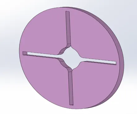
To create the driven component from given 2D Sketch, first open the SolidWorks new part file.
Then select Top plane, then sketch circle and draw 3 circles of given diameter, draw the given shape and trim the unnecessary lines.
And after the sketch is done Extrude it to 40mm. After extruding the 2D Sketch, the 3D Model will look like below:
Driving Component:
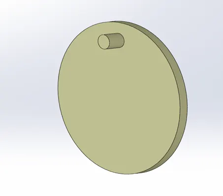
Open new part file and draw the 2D Sketch of the driving component and the sketch is extruded to the given dimensions. Following figure shows the 3D Model of the Driving component.
RESULTS:
For 10 RPM:
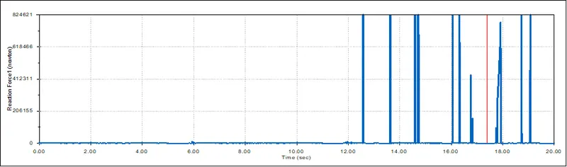
Contact force between the wheels at 10rpm:
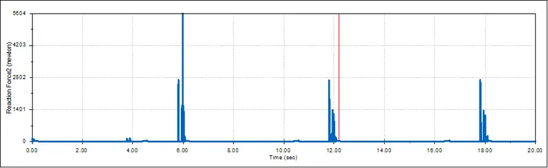
Contact force with precision contact at 10rpm:
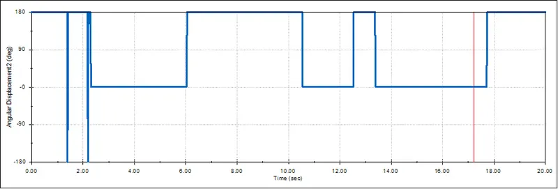
Angular Displacement of the driven wheel at 10 rpm:
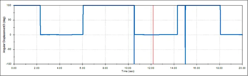
Angular Displacement of the driven wheel with precision contact at 10 rpm:
For 20 RPM:
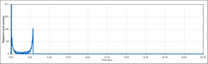
Contact force between the wheels at 20 rpm:
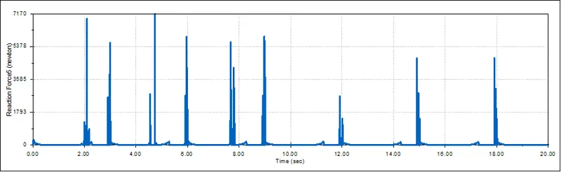
Contact force between wheels with precision contact at 20 rpm:
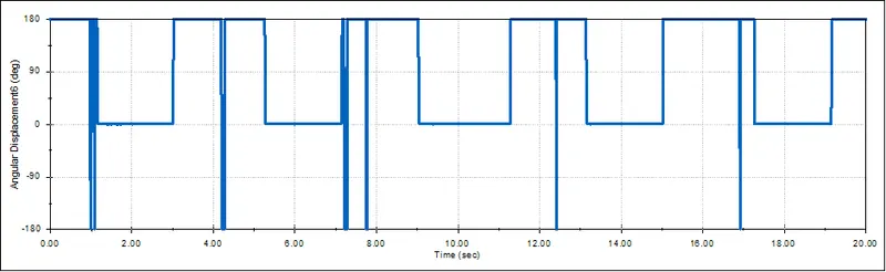
Angular Displacement of driven wheel at 20 rpm:
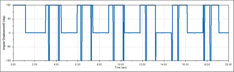
Angular displacement of driven wheel with precision contact at 20 rpm:
Conclusions:
- Contact forces without precision is not much accurate and it is more fluctuating while the contact forces with precision is more accurate and less fluctuating.
- We can see from the animation that when the driver tries to enter the slot of driven wheel it creates the jerk and it doesn’t enter with smoothness.
- The angular displacement plot shows that the displacement occurs between -180 to 180 degree.