Induction Motor Characteristics - II
1) Discuss the equivalent circuit network of the induction motor MATLAB model.
Equivalent circuit of an Induction motor:
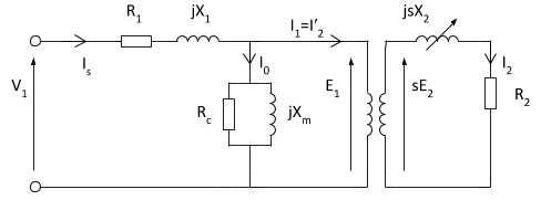
- In the equivalent circuit, R1 represents the resistance of the stator winding and X1 the stator leakage reactance (flux that does not link with the air gap and rotor). Magnetizing reactance required to cross the air gap is represented by Xm and core losses (hysteresis and eddy current) by Rc.
- An ideal transformer of N1 and N2 turns respectively represents the air gap. For the rotor side, the induced emf is affected by the slip (as the rotor gains speed, slip reduces and less emf is induced). The rotor resistance and reactance are represented by R2 and X2 with X2 being dependant on the frequency of the inductor rotor EMFs.
- In the rotor circuit, the current I2 is given by: `I2=(E2)/(sqrt(((R2)/s)^2+(X2)^2`
Slip:
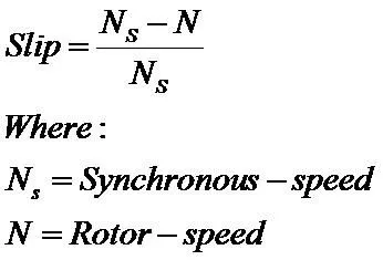
- Induction motors are asynchronous. The stator magnetic field rotates at the motor's synchronous speed (ns). The rotor can never rotate at synchronous speed, otherwise, there would be no induced current. Typically the rotor full speed will between 2 and 6% of that of the synchronous speed. The difference between the motor's synchronous and actual asynchronous speed is known as the slip.
- The difference between the motor's synchronous speed (ns) and actual rotor speed (nr) is known as the slip (s).
Frequency:
- From magnetic winding theory, the relationship between frequency in the stator (f), number of pole pairs (p), and the synchronous speed is given by:
`f=omegams*p`
Simplified equivalent circuit of an Induction motor:
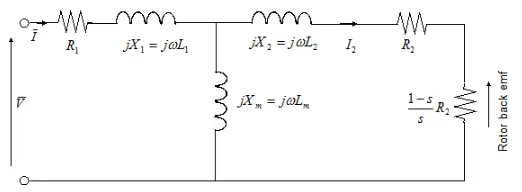
The Simplified Induction Motor block represents the electrical and torque characteristics of an induction motor powered by an ideal AC supply. The following figure shows the equivalent circuit model of the Simplified Induction Motor block.
In the figure:
-
R1 is the stator resistance.
-
R2 is the rotor resistance with respect to the stator.
-
L1 is the stator inductance.
-
L2 is the rotor inductance with respect to the stator.
-
Lm is magnetizing inductance.
-
s is the rotor slip.
-
`barV` and `barI` are the sinusoidal supply voltage and current phasors.
Rotor slip s is defined in terms of the mechanical rotational speed ωm, the number of pole pairs p, and the electrical supply frequency ω by
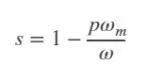
This means that the slip is one when starting, and zero when running synchronously with the supply frequency.
For an n-phase induction motor, the torque-speed relationship is given by:
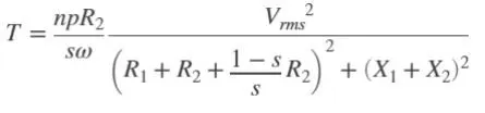
where:
-
Vrms is the line-neutral supply voltage for a star-configuration induction motor and the line-to-line voltage for a delta-configuration induction motor.
-
n is the number of phases.
You can parameterize this block in terms of the preceding equivalent circuit model parameters or in terms of the motor ratings the block uses to derive these parameters.
This block produces a positive torque acting from the mechanical C to R ports.
Thermal Ports:
- The block has two optional thermal ports, one per winding, hidden by default. To expose the thermal ports, right-click the block in your model, and then from the context menu select Simscape > Block choices > Show thermal port. This action displays the thermal ports on the block icon and exposes the Temperature Dependence and Thermal Port parameters. These parameters are described further on this reference page.
- Use the thermal ports to simulate the effects of copper resistance losses that convert electrical power to heat. For more information on using thermal ports in actuator blocks, see Simulating Thermal Effects in Rotational and Translational Actuators.
Assumptions and Limitations:
-
The block does not model the starting mechanism for a single-phase induction motor.
-
When you parameterize the block by motor ratings, the block derives the equivalent circuit model parameters by assuming that the effect of the magnetizing inductance Lm is negligible, and the magnetizing inductance is not included in the simulated component.
2) 3 phase, 50 Hz induction motor, represented by equivalent circuit constants X1 = X2 = 0.1 ohm and R1 = R2 = 0.2 ohm is operated at half of rated voltage and frequency. Calculate the ratio of starting torque at half voltage & frequency to rated values.
Given:
- No. of phases = 3
- Frequency = 50Hz
- Stator inductance, X1 = 0.1 ohm
- Rotor inductance, X2 = 0.1 ohm
- Stator resistance, R1 = 0.2 ohm
- Rotor resistance, R2 = 0.2 ohm
- operated at half of rated voltage and frequency
Governing Equation:
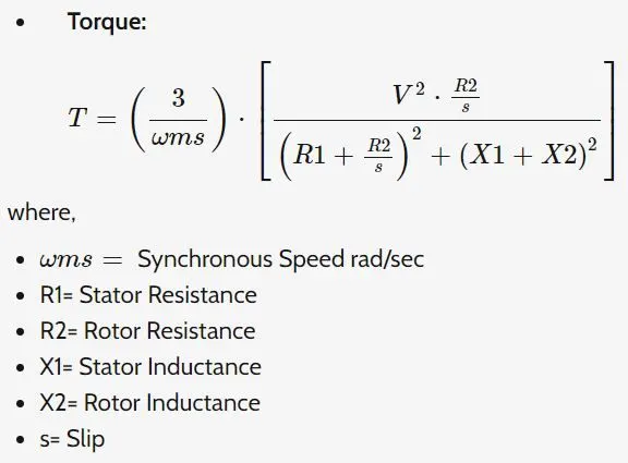
wkt,
- Rated frequency, f = 50Hz
- So, Half rated frequency, f' = 50/2 = 25Hz
Rated synchronous speed (`omegams or Ns)`
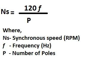
`omegams = (120*50)/p`
`=6000/p`
Half rated synchronous speed,
`omega'ms=(120*25)/p`
`=3000/p`
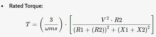
`=(3/(omegams))*[(V^2*0.2)/((0.2+(0.2)^2+(0.1+(0.1)^2))]`
`=(3*V^2)/(omegams)`
Half rated torque T',
T' = `1/2(`rated torque)
`= 1/2*(3*V^2)/(omegams)`
`=(1.5*V^2)/(omegams)`
The ratio of rated torque and half rated torque:
`(T')/T=((1.5*V^2)/(omegams)/(3*V^2)/(omegams))`
`=1/2=0.5`
`therefore`the ratio of Starting torque to half rated torque is `1/2`.
3) Make a comparison of square wave inverter output voltage with sine modulated one.
Square wave Vs Sine wave:
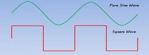
- The inverter converts battery DC electricity to AC electricity. DC signal looks like a unidirectional straight line and AC signal looks like waves of the ocean. DC waves cannot travel long so all our home electricity is supplied in AC manner.
- But the battery stores the power as DC, the inverter converts this DC current to somewhat similar to AC current. Depending on the inverter circuit, either inverter converts the DC current to Sine wave AC current or Square wave AC current
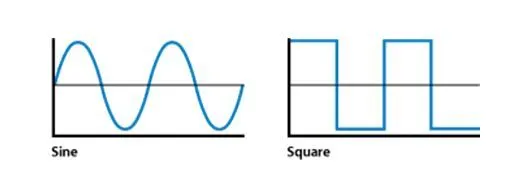
- Sine wave inverter output is very close to the AC current. It is a very pure form compared to Square wave output. Many devices get heated up if you use on Square wave inverter and make a humming noise too. Because of this reason, square wave inverters in few European countries are banned.
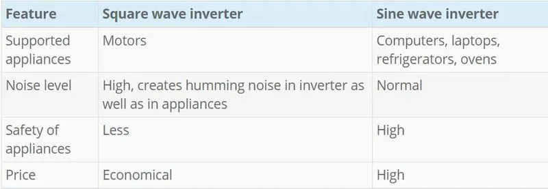
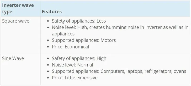
- Apart from that, there is another type called a modified sine wave inverter. It is not better than a sine wave, but a little better than a square wave, and a little cheaper than a sine wave. In some sense, it is positioned between a sine wave and a square wave. In fact, the number of models in India for modified square wave also less. We suggest not to got for a modified square wave. If money is not a concern it is always better to go for a sine wave inverter.
References: