FINAL TEST
PFI Engine:
1. What is the Compression ratio for the engine?
Compression ratio is defined as the ratio of the maximum to minimum volume in the cylinder of an internal combustion engine.
Compression ratio of an engine = `V_max/V_min`=`(V_d + V_c)/V_c`

`V_c =`Clearance Volume
`V_d=`Displacement volume
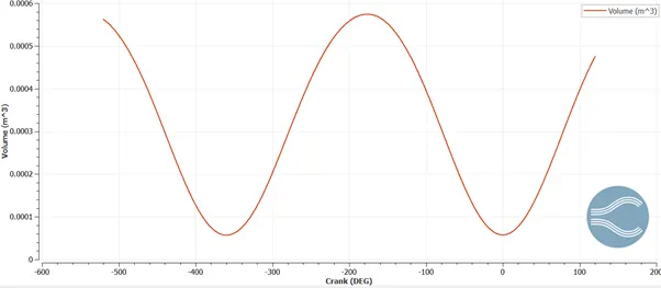
According to the simulation performed, and as per as the results,

A high compression ratio is desirable because it allows an engine to extract more mechanical energy from a given mass of airfuel mixture due to its higher thermal efficiency. This occurs because internal combustion engines are basically heat engines and higher efficiency is created because higher compression ratios permit the same combustion temperature to be reached with less fuel, while giving a longer expansion cycle, creating more mechanical power output and lowering the exhaust temperature.
2. Modify the compression ratio for this engine to 10.3 without changing geometrical parameters. Just need to show the calculation.
To modify the compression ratio for an engine without changing its geometrical parameters is possible only by changing its clearance volume or its displacement/swept volume
(i)By changing the displacement volume while keeping the clearance volume constant.
`V_max = 5.742*10^-5`
`V_min =5.70*10^-5`
And also,
`V_max = V_d + V_c`
`V_d = V_max - V_c`
So, `V_d =5.74*10^-4-5.70*10^-5=5.17*10^-4m^3`
Now, `r_c = V_max/V_min= (V_d + V_c)/V_c=10.3`
Upon substituting the value for `V_d`
we get `V_c =5.55*10^-5`
(ii)Now by keeping Dispacement volume constant and changing the clearance volume.
`r_c = V_max/V_min=(V_d + V_c)/(V_c)=10.3`
Now, substituting the Value of `V_c=5.70*10^-5`,we get Dispacement volume,`V_d=5.336*10^-3`
3.Calculate Volumetric Efficiency for this engine
The volumetric efficiency of an IC engine is given by the ratio of the volume of the air drawn into the cylinder during the suction stroke to the volume displaced by the piston. More specifically, volumetric efficiency is a ratio of the mass of air and fuel that is trapped by the cylinder during induction divided by the mass that would occupy the displaced volume if the air density in the cylinder were equal to the ambient air density.
The volumetric efficiancy expression is as shown below:

Thus it can be expressed as volumetric efficiency =`eta_a = V_a/V_d`
The displacement volume, `V_d =V_max-V_min=5.7842*10^-4m^3-5.702*10^-5m^3=5.1718*10^-4m^3`
= 0.00051718
The air inside the cylinder is considered as an ideal gas. Now, from the ideal gas equation , we can calculate the volume of air drawn inside the cylinder during the suction stroke.
Ideal gas equation for air is `P_a*V_a=m_aR_aT_a`
The pressure of the air during the suction is atmospheric pressure = `P_a`= 101325.0 Pa.
The temperature of air is atmospheric = = 300 K
From the mass vs Crank angle plot, `m_a=5.342*10^-4`
So,`V_a=(m_a*R*T_a)/P_a=(5.342*10^-4*287*300)/(101325.0)=4.5392*10^-4`
Now, Volumetric efficiancy =`(V_a/V_d)*100=(4.5392*10^-4)/(5.1718*10^-4)*100=87.7%`
4.Measure the air mass flow rate for this engine in kg/s
To find the air mass flow rate for the engine we need to know the mass of air which can be found out from the mass vs crank plot.
Mass of the air, m =0.000534 Kg
The mass of the air measured is the mass flow rate of air into the cylinder per one cycle ie, for 360 deg.
The speed of the engine is 3000 RPM.
So,
Speed of the engine in RPS =`3000/60=50 RPS`
As a result, the actual angle which is covered in one second is`50*360=18000 deg`
To find the mass of air entering into the engine at 18000 deg,
For Mass of air entering at 18000 deg =`5.34*10^-4*50=0.0267 (kg)/s` Kg/s
5.Why is the cell count varying during the simulation?
Total cell count varies throughout the whole simulation. This is because of the application of Advanced Mesh Refinement(AMR-With SGS) and Fixed Embedding.Adaptive mesh refinement is a method of adapting and enhancing the grid dynamically depending upon the variation in the second-order variation of parameters. When solutions are calculated numerically, they are often limited to pre-determined quantified grids as in the Cartesian plane which constitute the computational grid, or 'mesh'. So, total cell count is directly dependent on the AMR and Fixed Embedding.In the PFI engine simulation, velocity and temperature AMR's was applied to have accurate results in sensitive areas while coarsening the mesh in non-sensitive areas . A scale of 3 and subgrid scaling of 1 for velocity and a scale of 3 and subgrid scaling of 2.5 for temperature was provided..
The adaptive mesh refinement refines the cells in most sensitive areas where there is a difference in between the quantities being measured among the adjacent cells. This difference is dependent on the sub-grid scale criterion. If the difference is more than the sub-grid scale criterion, then the cells get refined. This is how mesh refinement works and is the basic reason for variation of cell count throughout the simulation.Fixed embedding refines the cells in particular specified parts of the geometry where accurate results are required and to capture the flow patterns accurately. This embedding may be permanent or cyclic.
6.
In a real engine, valves are in contact with the cylinder head but while running simulation, there is a small gap
- WHY?
The small gap is created in order to create and remove the disconnect triangles which converge automatically creates by default and that was possible due to the activation of events. The events are created for the opening and closing of valves during different compression strokes.
- What happens if this gap is big?
If the gap is big, then the fuel flow inside the cylinder will be large enough and there will be a abrupt sudden increase in the amount of fuel; that is entering into the combustion chamber as a result, it will not provide realistic results and the deviation would be significant from the rfeal engines.So in simulation study, the gap should be maintained low and the application of events will allow how much the fuel ios entering into the cylinder through successive compression strokes and to make sure there is no abrupt increase in the injected fuel entering into the chamber.
7.How many seconds does combustion last in this case?
From the engine performance calculator available in CONVERGE it was seen that the engine is run through 240 deg in the combustion stroke.
The engine speed was 3000 RPM or 50 RPS. And we know that the engine covered 18000 deg in one second ie, 360x60 = 18000 deg.
Now to find how many seconds the engine shall take to cover 240 deg, is `240/18000=0.0133 s`
Diesel Engine:
1. What is an advantage of SECTOR Simulation?
The main advantage of the sector Simulation i.e dividing the whole geometry into each sectors and simulating one by one is for high computational efficiency. This also helps in faster run time and smooth running of simulation. As this is a closed cycle simulation the number of parameters used and boundary conditions required is minimum in order to reduce the complexity of the Case Setup. The cylinder head, valves and the ports of the IC engine were not present in the Diesel engine simulation for which the expansion and compression stroke is simulated with greater efficiancy.
2. When will the sector approach not work?
The approach of creating sector geometry does not work when the geometry is not symmetric which is obvious as the unsymmetric geometries cannot create a sector which can represent a total geometry when the identical sectors are joined together . It also does not work when the geometry has an inlet and outlet port i.e open cycle simulation.In open cycle approach the engines valevs both the intake and exhaust are kept open for which they are part of the simulation and needs to modelled and simulated too with proper boundary conditions since the position of the valves vary in such an approach. As a result,by creating sectors it will fail to capture the effects of the translatory motion of the valves with respect to time.
3.How to choose Start Crank Angle (SCA) and End Crank Angle (ECA) for a sector simulation?
The beginning of the simulation can be taken at the beginning of the compression stroke and the end of the simulation can be taken at the end of the expansion stroke.Start Crank Angle (SCA) at the start of the compression stroke and the End Crank Angle (ECA) at the end of the
expansion stroke. If the start of the suction stroke can be taken as 0 degree Crank angle, start of the compression-180 deg crank angle and end of the expansion stroke-540 deg Crank angle which implies start Crank angle is 180 deg and end crank angle is 540 deg.
4. Can we convert the PFI case into a SECTOR case? Explain your answer?
No, the PFI case cannot be convereted into a sector case because it includes intake and exhaust ports and also the injection source situated at the intake port which hence cannot be divided into a sector. So The PFI case cannot allow a sector simulation as the sector simulation is approached by closed and symmentric geometry and the PFI Case was for open system approach.