Fender Design Challenge
- Title of the Project:
Design of Front Fender using External Skin Data Through NX CAD 12.
- Objective:
To design and model the front fender and its mounting areas using master section data and skin data, through NX CAD 12.
- Introduction:
Sheetmetal are widely used in generating the automotive body components, which is due to their lighter in mass, easy manufacturability, low cost of production and product within the time constraints and also helps in gaining design competencies of a component easily and accurately. Sheetmetal thickness may vary from 0.3mm to 12mm.they can be easily transformed into final model using simple pressing and bending operations. Sheetmetal components can be either a single part or tailored blanked part. Front fender is a component which plays a vital role in gaining safety standards and also in aesthetics appearances. Whenever while designing the front fender, there are some major base data in order to satisfy. Therefore, a detailed report on how the front fender and its mounting regions is modelled and developed will be generated in this project by considering various factors followed in front fender.
- Methodology:
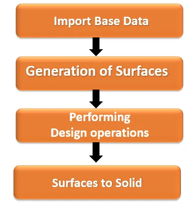
5. Description of Methodology:
- Import Base data:
It is an initial stage of generating front fender. The skin profile body is imported to NX Workbench and its master section data is clearly analysed.
- Generation of Surfaces:
Based on the skin data, by offsetting the parent surface the actual working surfaces are created as per the design of master section.
- Performing Design operations:
After generating surfaces, the sketching is done on the various plane of fender. Using this profile, the embossing operations are performed, cut-out is generated on the fender. Further trimming, extending, Dart, thicken and sewing operations were carried out on the fender.
- Surface to Solid:
Once the surfaces of front fender are completed as per the reference. the entire body surfaces are converted into solid body by providing the thickness value for the front fender, as per the master section data.
6. Steps followed in design Process:
- Importing of skin profile data (Front Fender).
- Offsetting of fender to create working surface as per the master section data.
- Sketching of profile on the fender by selecting various plane in order to create the embosses.
- Creating of Drip mounting, A-pillar, Sill, Bumper, C mounting and Splash mountings across the front fender.
- Creating of dart on the drip, A-pillar, and bumper mounting regions.
- Trimming, extending and sewing of surfaces as per design requirement.
- Performing face blend operations across the fender.
- Selecting the entire front fender surfaces and converting them into a solid part by providing the thickness value based on the master section data
7.Front Fender with Standards :
Fender are the components which houses the wheel inside it. these fender helps in protecting the engine cradle damage caused by wheel during its rotation. Whenever the vehicle is moving in various surface condition, the wheel tends to throw the stones and other hard particles at their surroundings. Which results in chipping of parts, damaging of surfaces which leads to cracks and end up with rust.it also helps in providing pedestrian safety. Therefore, these fenders help in preventing those damages occurred through wheels by acting as a housing. Fenders also known as mudguards.
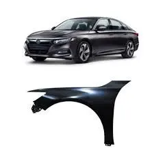
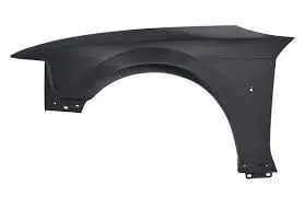
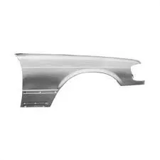
There are different standard regulations that are followed across the globe, which is due to their regional factors such as surface conditions, government norms, weather conditions etc.
Japan Standards:
In case of Japan standards, the clearance value must be greater than 5 mm in all points of fender curvature in order to satisfy their fender design standard requirement i.e., at position A, B, C the value must be more than 5mm at the line 30° and 50° from the mid axis of wheel.
European Standards:
In case of European standards, the clearance value must be greater than 10 mm in all points of fender curvature in order to satisfy their fender design standard requirement i.e., at position A, B, C, D, E the value must be more than 10 mm at the line 30° ,50° and Ofsted references from the mid axis of wheel.
American Standards:
In case of American standards, the clearance value must be greater than 5 mm in all points of fender curvature in order to satisfy their fender design standard requirement i.e., at position from -20° to 180° at the intervals of 10°, the value must be more than 5 mm from the mid axis of wheel.
8. Fender Mounting Regions:
- Drip Mounting:
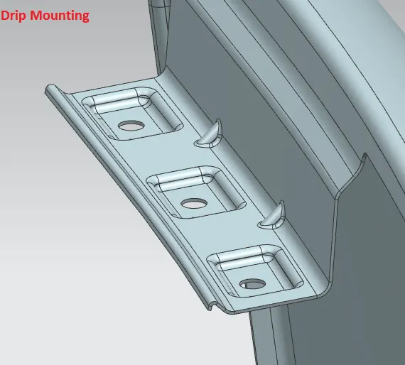
It is a mounting region, through which the front fender is mounted on engine cradle housing using temporary fasteners. this drip area has the standard values to satisfy, which is the length of drip region from the front hard lamp housing should be 150mm and from the engine cradle housing it should be around 200mm.
- A-Pillar Mounting:
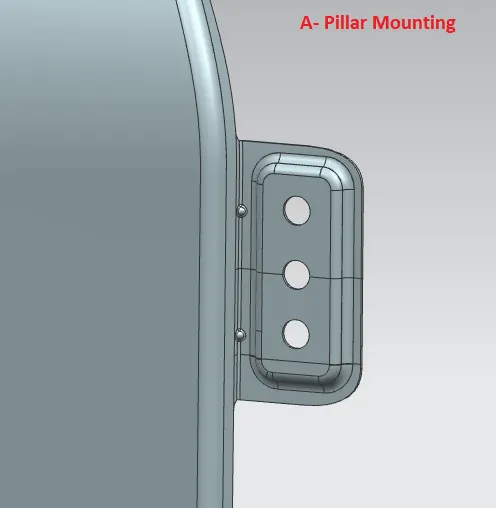
It is a mounting region, through which the front fender is mounted on A-pillar using temporary fasteners-pillar are located near front windshield on either side of the car. These mountings get closed when the outer rear-view mirrors are assembled to car.
- Sill Mounting:
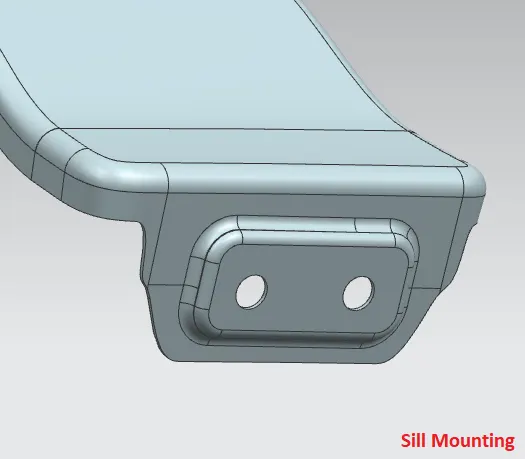
It is a mounting region, which is created on the extreme bottom side of the front fender. This sill mounting will be aligned to the running board or some times front door closer regions of the car using temporary fasteners.
- Bumper Mountings:
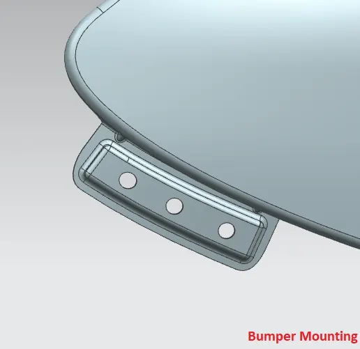
These are the mounting regions provided on fender, which tends to align with the front bumper using fasteners. These bumper mounting regions needs to be stronger in order to manipulate the impact forces during pedestrian contact and collision.
- C and Splash Mounting:( Baffle mountings):
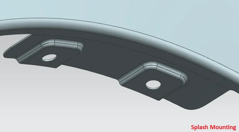
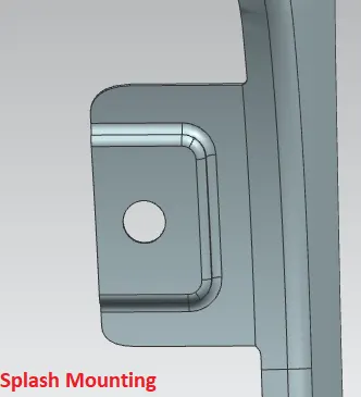
These are the mounting regions, which are provided at outer wheel arch radius of the front fender. These mountings of the fender are aligned with the inner baffle panels or mud guards using the fasteners. These are also known as baffle mountings.
- Embossed Surfaces:
Embossed surfaces are normally generated in hood inner panel of the hood assembly. These embossed surfaces are created on the panel order to improve the crash worthiness of the hood component. Most of the embossed surfaces will be having a draft angle which is in v-section which is due to during any of the impact, the force which is acting towards the hood will be received by inner panel and diverted them towards the corners and edges of the embossed surfaces which results in reducing the impact forces which is travelling towards the passengers inside the cabin.
- Fender Manufacturing Process:
Fenders are manufactured using various process such as pressing, stamping, drawing operations.
the workpiece Sheetmetal blank is radially dragged into a forming die by means of punch pressing force actuated by machines. Once the punch is executed the design forming is generated with material retention.
These Sheetmetal forming operation, are commonly used in manufacturing of automobile BIW components which is due to its precision, production time, and quantity.
9.Modelled Components:
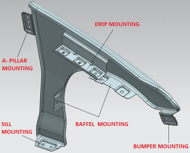 Fender with various mounting regions
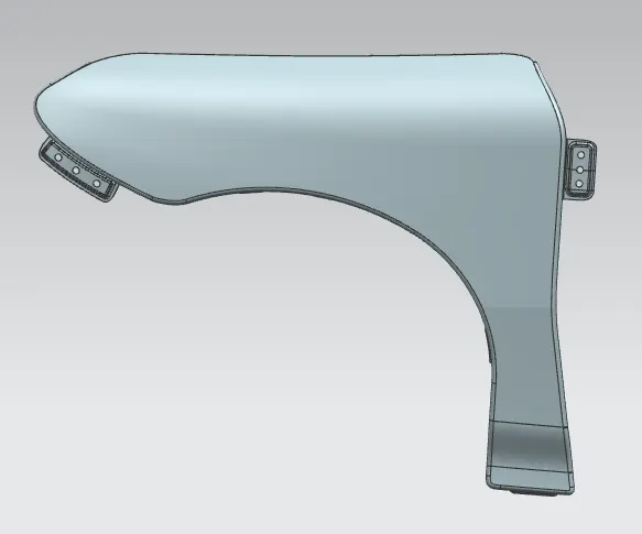
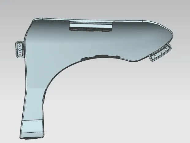
Front view Rear view
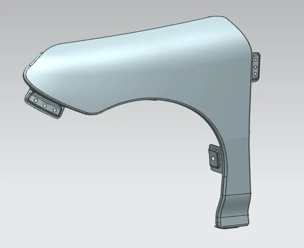
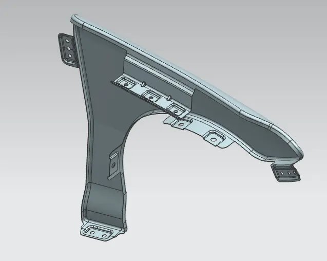
Isometric view Trimetric view
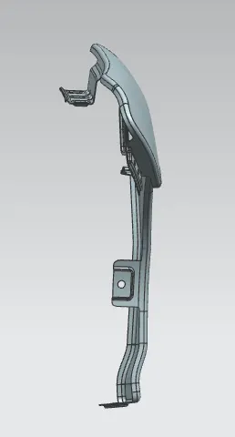 Side view
- Conclusion:
The design and modelling of front fender has been generated successfully, as per the dimensions provided in master section data using the skin profile model through NX CAD software tool. The final front fender component tends to appear as the exact replica of the given reference model. The NX CAD helps to make the design accomplishment easier within time constraint.